Page 777 of 2189

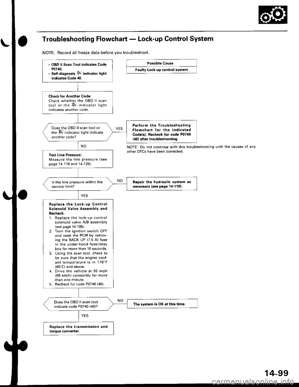
Troubleshooting Flowchart - Lock-up Control System
NOTE: Record all freeze data before vou troubleshoot.
Possibl€ Cause
Faulty Lock-up control sy3tem
NOTE: Do not continue with this troubleshootingother DTCS have been corrected.until the causes of any
OBD ll Scan Tool indicates Codem14/J.S€lf-diagnosis .D4l indicalor lightindicates Code 40.
Check for Another Code:Check whether the OBD ll scantool or the :E indicator lightindicates another code,
Perform the TroubleshootingFlowchart tor the indicatedCodels|. Rocheck to. code P0740(40) .fter troublBhooting.
ooes the OBD ll scan tool orrhe E indicator light indicateanother code?
Test Line Pressure:Measure the line pressure (see
page 14 119 and 14-120).
Repair the hydrrulic sy3tem asn6c6ssary (see page 14-1191.ls the lane pressure within theservice limit?
Replace the Lock-up ControlSolenoid Valve Assembly andRecheck:1. Replace the lock-up controlsolenoid valve A/B assembly(see page 14-105).2. Turn the ignition switch OFFand reset the PCM by removing the EACK UP (7.5 A) fusein the underhood {use/relaybox for more than 10 seconds.3. Using the scan tool, check tobe sure that the engine cool-ant temperature is in 176'F(80'C) and above.4. Drive the vehicle at 55 mph(88 km/h) constantly for morethan one minute,5. Recheck for code P0740 {40).
Does the OBD ll scan toolindicate code P0740 (40)?The svstem i3 OK .t this time.
14-99
Page 789 of 2189
The following symptoms can be caused
by improper repair or assembly
Check these items,on th€^ ltems on thePROBABLE CAUSE DUE TO NOTES ListIMPROPER REPAIR List
Vehicle creeps in N position.R1, R2
Vehicle does not move in &l or Pll position.R4
Transmission locks up in E position.R3, R11
Excessive drag in transmission.R6K,R
Excessive vibration, rpm related.R7
Noise with wheels moving onlY.R5
Main seal pops out.R8
Various shifting problems.R9, RlO
PROBABLE CAUSE DUE TO IMPROPER REPAIR
lmproper clutch clearance.
lmproper gear clearance.
Park lever installed upside down.
one-way {sprag) clutch installed upside down.
Reverse selector hub installed upside down.
ATF pump binding.
Torque converter not fully seated in ATF pump.
Main seal improperly installed.
Springs improperly installed.
Valves improperly installed.
Shift fork bolt not installed.
14-11
Page 815 of 2189

NOTE;
. Clean all parts thoroughly in solvent or carburetor
cleaner, and dry with compressed air.
. Blow out all passages.
. When removing the valve body, replace the O-ring.
l, Remove the ATF feed pipes from the servo body,
secondary valve body and main valve body.
For'96 - 98 models: Remove the ATF strainer and
servo detent base (two bolts).
For'99 - 00 models: Remove the ATF strainer (one
bolt).
Remove the servo body and servo separator plate
{'96 - 98 models: seven bolts,'99 - 00 models: eight
bolts).
Remove the secondary valve body, shaft stop and
secondary separator plate (three bolts).
Remove the lock-up valve body and separator plate
{seven bolts).
Remove the regulator valve body (one boltl.
Remove the stator shaft and stop shaft.
Remove the detent spring from the detent arm. then
remove the control shaft from the to.que converter
housing.
Remove the detent arm and detent arm shaft from
the main valve body.
Remove the main valve body (five bolts).
NOTE: Do not let the eight check balls fall outofthe
main valve body when removing the main valve
body.
Remove the ATF pump driven gear shaft, then remove
the ATF pump gears.
Remove the main separator plate and two dowel
pins.
7.
't'1.
10.
12.
14.
13. CIean the inlet opening of the ATF strainer thor-
oughly with compressed air. then check that it is in
good condition, and the inlet opening is not clogged.
INLET OPENING
Test the filter by pouring clean ATF fluid through
the inlet opening. Beplace the ATF strainer if it is
clogged or damaged.
NOTE: The ATF str8iner can be reused if it is not
clogged.
14-137
Page 817 of 2189

Valve Body
2.
Repair
NOTE: This repair is only necessary if one or more of
the valves in a valve body do not slide smoothly in their
bores. You may use this procedure to free the valves in
the valve bodies.
1. Soak a sheet of #600 abrasive paper in ATF for
about 30 minutes.
Carefully tap the valve body so the sticking valve
drops out of its bore.
CAUTION: lt may b€ necessary to use a small
screwdriver to pry the valve free. Be careful not to
scratch the bore whh the screwdriver.
Inspect the valve for any scuff marks. Use the ATF-
soaked #600 paper to polish off any burrs that are
on the valve, then wash the valve in solvent and dry
it with compressed a ir.
Roll up half a sheet of ATF-soaked paper, and insert
it in the valve bore of the sticking valve.
Twist the paper slightly, so that it unrolls and fits the
bore tightly, then polish the bore by twisting the
paper as you push it in and out.
CAUTION: The valve body is aluminum and doesn't
require much polishing to remove any burrs,
3.
4.
ATF-soaked#600 abrasive Paper
5.
7.
Remove the #600 paper and thoroughly wash the
entire valve body in solvent. then dry it with com-
pressed air.
Coat the valve with ATF, then drop ir into its bore.
It should drop to the bonom of the bore under its
own weight. lf not, repeat step 4, then retest.
VALVE BODY
Remove the valve. then thoroughly clean it and the
valve body with solvent. Dry all parts with com-
pressed air. then reassemble using ATF as a lubri
cant.
W
-M
14-139
Page 820 of 2189
Main Valve Body
Disassembly/lnspection/Reassembly
NOTE:
. Cleanall parts thoroughly in solvent or carburetor cleaner, and drywith compressed air. Blowoutall passages.. Replace the valve body as an assembly if any pans are worn or damaged.. Check all valves for free movement. lf anyfail toslidefreely, see Valve Body Repairon page,l4-139.. Coat all parts with ATF during assembly.
CAUTION: Do not use a magnet to removs tha check balls; it may magnetizo the balls.
CPB VALVEVALVE CAP CLIP
ORIFICE CONTROL VALVE
BALLS, 8
lST ACCUMULATOR CHOKE
MODULATORVALVE
RELIEF VALVEVALVE
MAIN VALVE EODYInspect for wear, scratchesand scoring.
SEBVO CONTROL VAL
I.2 SHIFT VALVE
14-142
VALVE CAP
Page 822 of 2189

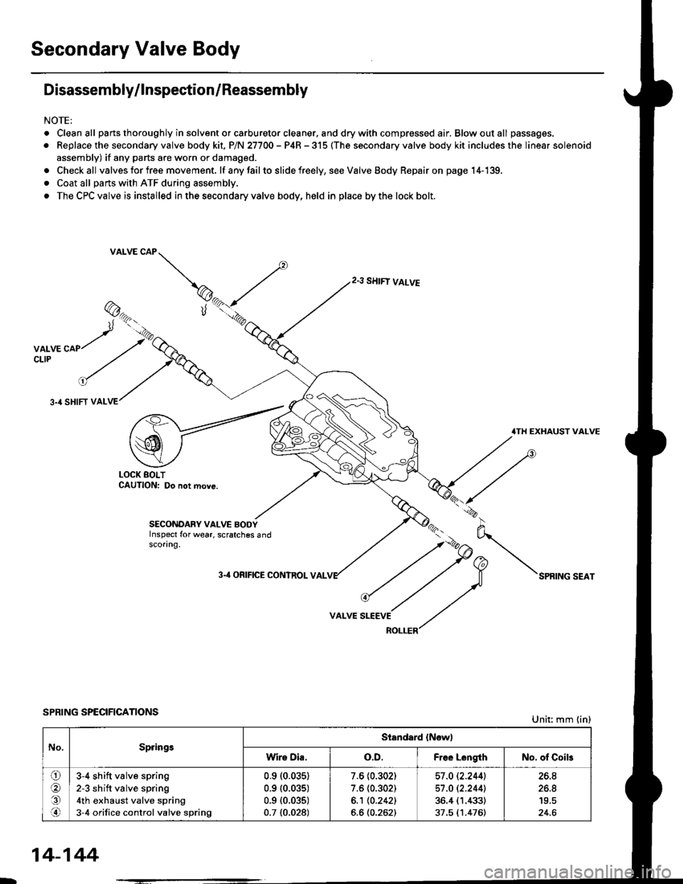
Secondary Valve Body
Disassembly/lnspection/Reassembly
NOTE:
. Cleanall parts thoroughly in solvent or carburetor cleaner. and drywith compressed air, Blowoutall passages.
. Replace the secondary valve body kit. P/N 27700 - P4R - 315 (The secondary valve body kit includes the linear solenoid
assembly) if any parts are worn or damaged.
. Checkall valves for free movement. lf anyfailto slide freely, seeValveBody Repairon page 14-139,
. Coat all parts with ATF during assembly.
. The CPC valve is installed in the secondary valve body, held in place by the lock bolt.
2.3 SHIFT VALVE
3.4 SHIFT VAL
.TH EXHAUST VALVE
LOCK BOLTCAUTION: Do not move.
SECONDARY VALVE BODYInspect for wear, scratches 6ndscoring.
3-'l ORIFICE CONTROL VAL
VALVE
SPRING SPECIFICATIONSUnit: mm (in)
No.SpringsStandard {New)
Wire Dia.o.D.Free LongthNo. of Coils
ora,.n
3-4 shift valve spring
2-3 sh ift valve spring
4th exhaust valve spring
3-4 orifice control valve spring
0.910.035)
0.9 {0.035)
0.9 {0.035)
0.7 {0.028)
7.6 (0.302)
7.6 (0.302)
6.1 10.2421
6.6 (0.262)
57 .O 12.2441
57 .O 12.2441
36.4 (1.433)
37.5 (1.476)
26.8
26.8
24.6
14-144
Page 823 of 2189

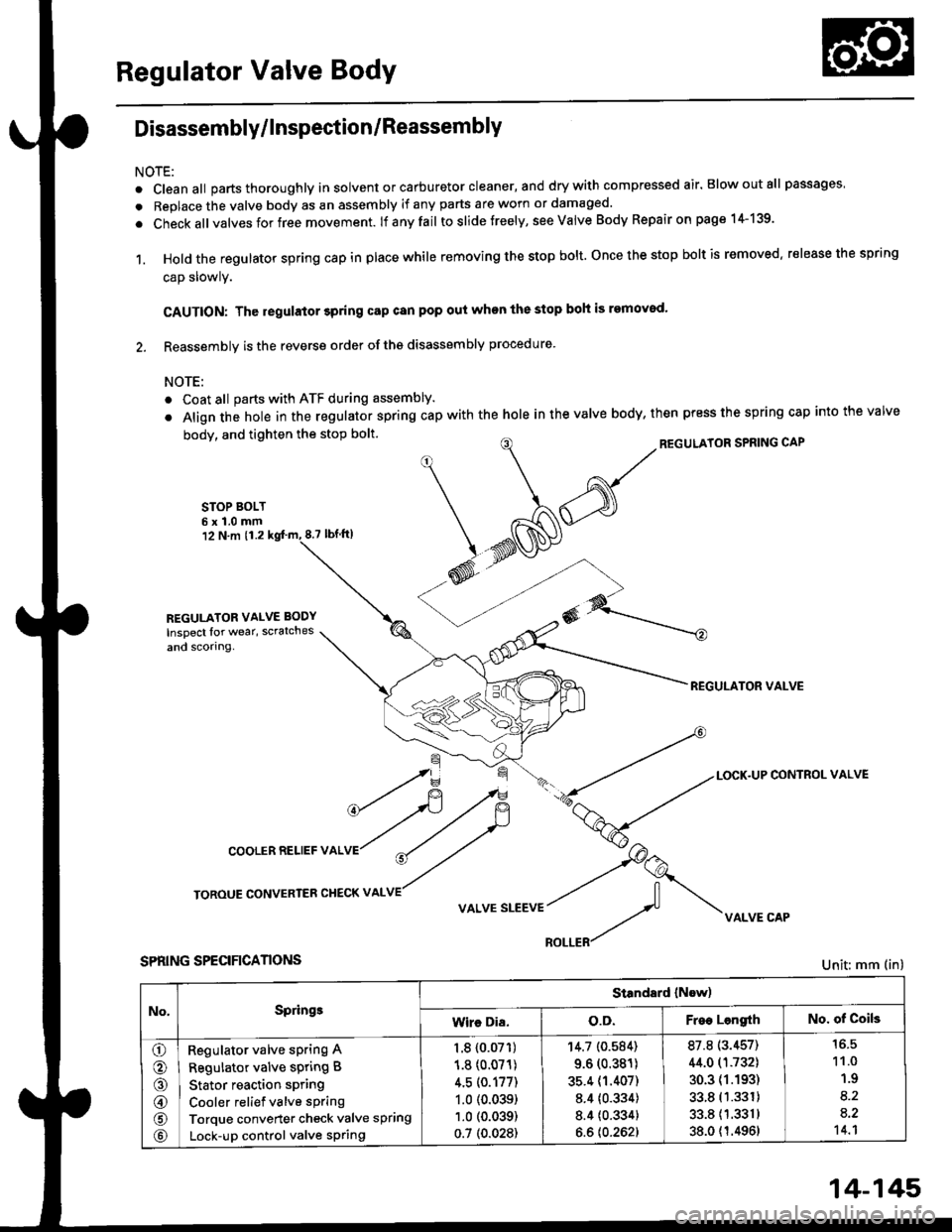
Regulator Valve Body
Disassembly/lnspection/Reassembly
NOTE:
. cleanall parts thoroughly in solvent or carburetor cleaner, and drywith compressed air. Blowoutall passages
. Replace the valve body as an assembly if any parts are worn or damaged.
. check allvalves for free movement. lf anyfail toslidetreely, see valve Body Repairon page 1+139.
1. Hold the regulator spring cap in place while removing the stop bolt. once the stop bolt is removed. release the spring
cap slowly.
CAUTION: The regulator 3pring cap can pop out when the stop boh is removod'
2. Reassembly is the reverse order ofths disassembly procedure.
NOTE:
o Coat all parts with ATF during assembly.
. Align the hole in the regulator spring cap with the hole in the valve body, then press the spring cap into the valve
body, and tighten the stop bolt.
STOP BOLT6x1.0mm12 N.m 11.28.7 tbf.lrl
^/^'ou*'oRsPRrNGcAP
*N@
REGULATOR VALVE
\=f -.-*
*fi /F { a-tLocK.uPcoNrRoLvALVE
cooLERRELlEFvALVr"r?
ry
roRouE coNvERrER cHEcKv ^LvE//
v ^r* "r**::f vi{LvE cAp
SPRING SPECIFICANONS
REGULATOR VALVE BODY
Inspect lor wear, scratches
and scorlng.
Unit: mm (in)
No,Springe
Standard (Now)
Wire Dia.o.D.Free LengrthNo. of Coils
o
o
@
@
@
Regulator valve sPring A
Regulator valve spring B
Stator reaction spring
Cooler relief valve spring
Torque converter check valve spring
Lock-up control valve sPring
1.8 {0.07'�r)
1.8 (0.071)
4.5 (0.177)
1.0 (0.039)
1.0 (0.039)
0.7 (0.028)
'r4.7 (0.584)
9.6 (0.381)
35.4 (1.407)
8.4 {0.334)
8.4 {0.334}
6.6 {0.262}
87.8 (3.457)
44.0 (1.732)
30.3 (1.193)
33.8 (1.331)
33.811.3311
38.0 {1.4961
11.0
1.9
8.2
a.2't 4.1
14-145
Page 824 of 2189

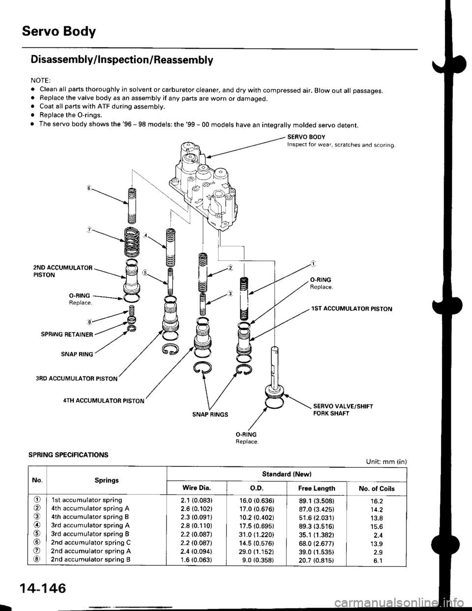
Servo Body
Disassembly/lnspection/Reassembly
NOTEI
. clean all parts thoroughly in solvent or carburetor cleaner, and dry with compressed air. Blow out all passages.. Replace the valve body as an assembly if any parts are worn or damaged.. Coat all parts with ATF during assembly.
. Replace the O-rings.
. The servo body shows the '96 - 98 models: the '99 - 00 models have an integrally molded servo detent.
SERVO BODYInspect for wear, scratches and scoring.
,______.- g
1l
v
"-------'g
ZruO lCCUr,irUr-nrOn ---rrr___-p
n\='l
3,ii11---------*5
^rrr4
I
O.RINGReplace.
3RO ACCUMULATOR PISTON
4TH ACCUMULATOR PISTON
SPRING SPECIFICATIONS
SNAP RINGS
1ST ACCUMULATOR PISTON
Unit: mm (in)
No.SpringsStandard {New)
Wire Dia.o.D.Free LengthNo. of Coils
o(a
@)
o
@
'I st accumulator spring
4th accumulator spring A
4th accumulator spring B
3rd accumulator spring A
3rd accumulator spring B
2nd accumulator spring C
2nd accumulator spring A
2nd accumulator spring B
2.1 (0.083)
2.6 (0.102)
2.3 (0.091)
2.8 (0.110)
2.210.0871
2.2 t0.0a7l
2.4 (0.094)'1.6 (0.063)
16.0 (0.636)
17.0 (0.676)
10.2lo.402J
17.5 (0.695)
31.0 11.220)
14.5 (0.576)
29.0 (1.152)
9.0 (0.358)
89.1 (3.s08)
87.0 (3.425)
51.6 (2.031)
89.3 (3.516)
35.1 (1.382)
68.012.677)
39.0 (1.535)
20.7 (0.815)
14.2
13.8
'13.9
L
14-146