1996 HONDA CIVIC Cvt
[x] Cancel search: CvtPage 2134 of 2189
\
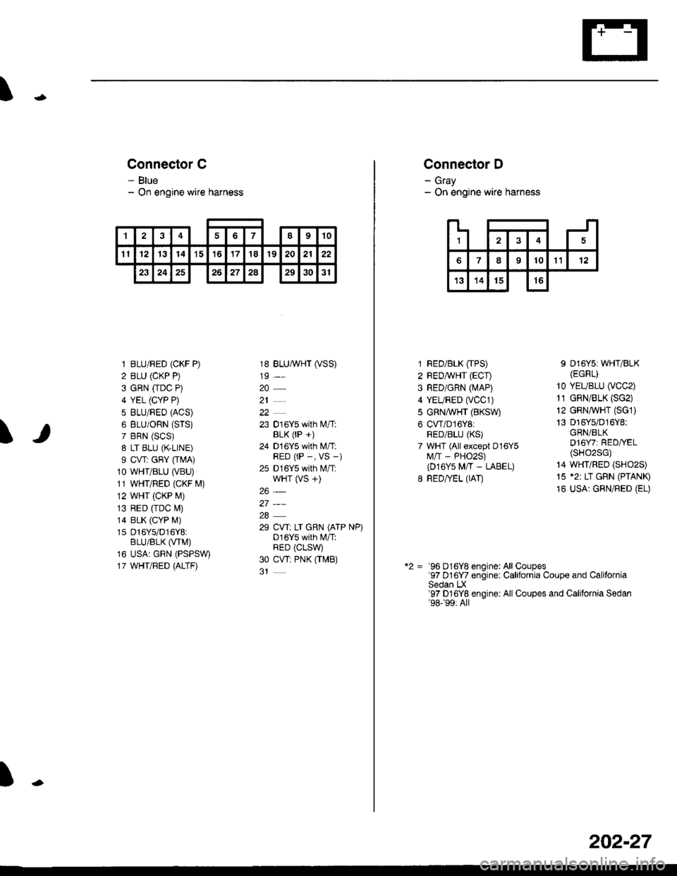
Connector C
- Blue- On engine wire harness
\
1 BLU/RED (CKF P)
2 BLU (CKP P)
3 GRN [rDC P)
4 YEL (CYP P)
5 BLU/REO (ACS)
6 BLU/ORN (STS)
7 BRN (SCS)
8 LT BLU (K.LINE)
I CVT: GRY [rMA)10 WHT/BLU (VBU)
11 WHT/RED (CKF M)
12 WHT (CKP M)
13 RED [rDC M)
14 BLK (CYP M)
1s Dl6Ys/D16Y8iBLU/BLK (VTM)
16 USA: GRN (PSPSW)
17 WHT/RED {ALTF)
18 BLUA/VHT (VSS)
19 -,.
20
21
22
23 016Y5 with l\.4/T:BLK (lP +)
24 D 16Y5 with M/T:RED (rP -, VS -)
25 D16Y5 with M/T:wHT (VS +)
26_
27_
28
29 CW: LT GRN (ATP NP)D16Y5 with l\4/T:RED (CLSW
30 CW: PNK OMB)
t
'I48910
11121314't5't6171819202122
23242526272a293031
L
124
789101112
13141516
Connector D
- Gray- On engine wire harness
1 RED/BLK [TPS)2 REDMHT (ECI)
3 RED/GRN (MAP)
4 YEURED (vCC1)
5 GRN,A/VHT (BKSW)
6 CWD16Y8:RED/BLU (KS)
7 WHT (All except D16Y5M/'T - PHO2S)(D16Y5 M/T - LABEL)
8 RED/YEL (IAT)
I D16Y5i WHT/BLK(EGRr)
10 YEUBLU (VCC2)
11 GRN/BLK (SG2)
12 GRN,ryVHT (SG1)
13 016Y5/D16Y8:GRN/BLKD16Y7: RED//EL(sHo2sG)
14 WHT/REO (SHO2S)
15 '2: LT GRN (PTANI9
16 USA: GRN/RED (EL)
*2 = '96 D16Y8 enoine: All Coupes97 D16Y7 enoine. Calitornia Couoe and CaliforniaSedan LX'97 D16Yg engine: All Coupes and California Sedan'98-�99:All
202-27
Page 2135 of 2189
Connector Views (conrd)
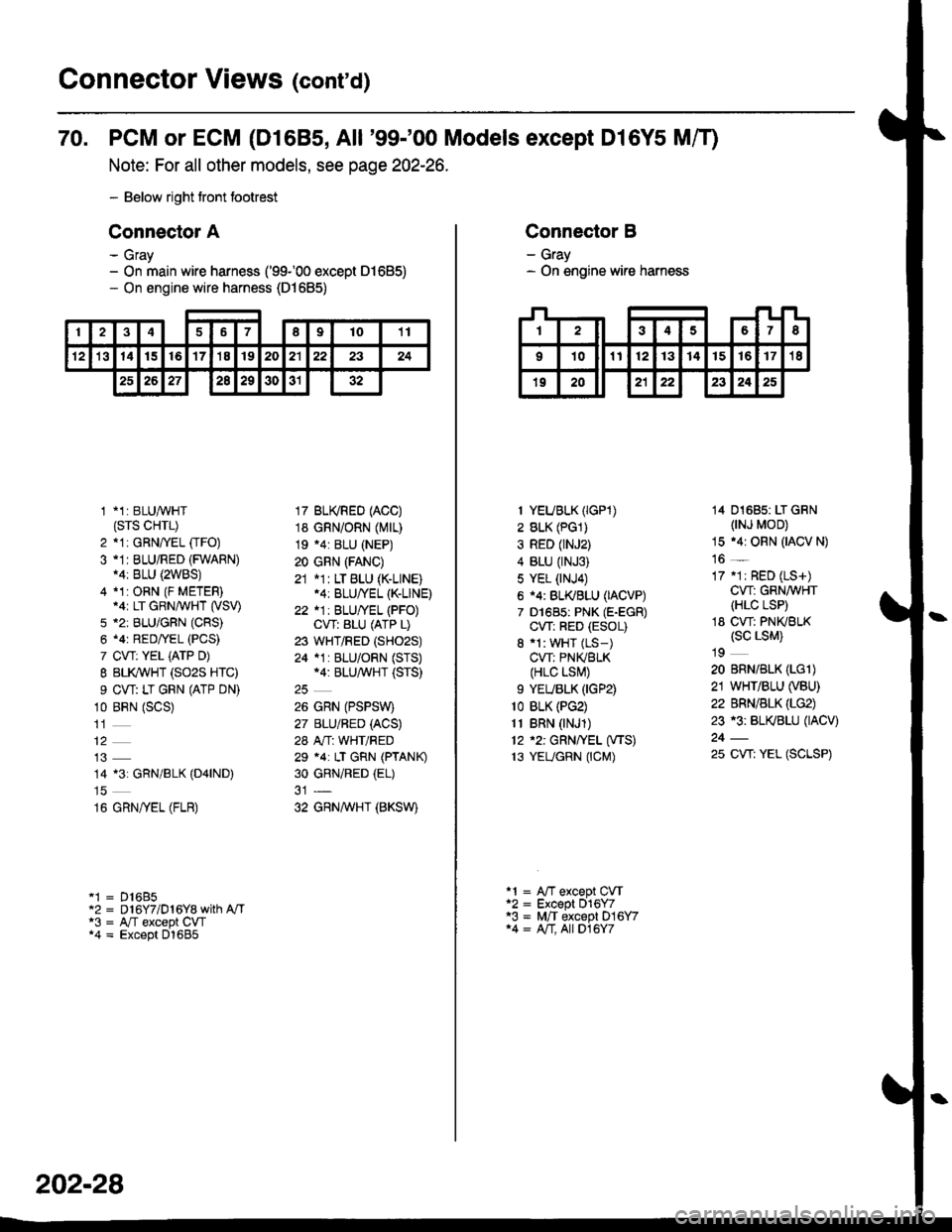
70. PCM or ECM (D1685, All '99-'00 Models except Dl6Y5 Mff)
Note: For all other models, see page 202-26.
- Below right tront footrest
Connector A
- Gray- On main wire harness ('99100 except 01685)- On engine wire harness (D1685)
246789t011
't21314t516'17'18192021222324
2526272a29303132
1 *1: BLUAVHT(srs cHrL)
2 *1: GRNffEL [rFO)3 -1I BLU/RED (FWARN)14: BLU {2WBS)4 *1:ORN (F METER).ar LT GRN/WHT (VSV)
5 *2: BLU/GFN (CRS)
6 .4r RED/YEL (PCS)
7 CVT: YEL iATP D)
I BLI(WHT (SO2S HTC)
9 CW: LT GRN (ATP DN)
10 BRN (SCS)
14 13: GRN/BLK (D4|ND)
16 GRN/yEL (FLR)
'1 = D16B5"2 = D 16Y7/D 1 6Y8 with A"/Ta3 = A,/T except CW*4 = Except D1685
17 BU(RED (ACC)
18 GRN/ORN (Mrr)
19 .4: BLU (NEP)
20 GRN (FANC)
21 *1: LT BLU (K-LINE).4: BLU/YEL (K-LINE)
22 *1: BLU/YEL (PFO)CVT: ALU (ATP L)
23 WHT/RED (SHO2S)
24 *1 : BLU/ORN (STS)*4: BLU/^,iVHT (STS)
26 GRN (PSPSW)
27 BLU/BED (ACS)
28 A"/T: WHT/RED
29 *4: LT GRN (PTANK)
30 GRNiRED (EL)
32 GRNAVHT (BKSW)
202-28
Connector B
- Gray- On engine wire harness
I YEUBLK (IGP1)
2 BLK (PG1)
3 RED (rNJ2)
4 BLU (rNJ3)
5 YEL (NJ4)
6 i4: BL(BLU (IACVP)
7 D1685: PNK (E-EGR)
CW: RED (ESOL)
8 'l: WHT (LS-)
CVT: PNIVBLK(HLC LSI\,!)
9 YEUBLK (IGP2)
1o BLK (PG2)
11 BRN (NJ1)
12 '2: GRN/YEL (VTS)
13 YEUGRN (CM)
14 01685: LT GRN(NJ MOD)
15 .4r ORN (IACV N)
16 _
17 .1r RED (LS+)
CW: GRN/WHT(HLC LSP)
18 CW: PNKBLK(sc LsM)
19
20 BRN/BLK (LGl)
21 WHT/BLU (VBU)
22 BRN/BLK (LG2)
23 r3: BL(BLU (IACV)
25 CW: YEL (SCLSP)
a1 = A"fT except CVTa2 = Except 016Y7'3 = M,/T except D16Y714 = A/T, All D16Y7
Page 2137 of 2189
Connector Views (conrd)
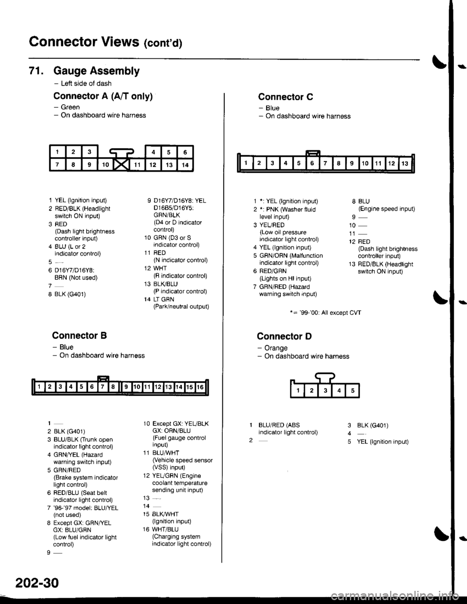
71. Gauge Assembly
- Left side of dash
Connector A (A/T only)
- Green- On dashboard wire harness
1 YEL (lgnition input)
2 RED/BLK (Headlight
switch ON input)
3 RED(Dash light brightnesscontroller input)
4 BLU (L or 2indicator control)
6 D16Y7/D16Y8:BRN (Not used)
8 BLK (G401)
Connector B
- Blue- On dashboard wire harness
2 BLK (G401)
3 BLU/BLK (Trunk openindicator light control)
4 GRN/YEL (Hazard
warning switch input)
5 GRN/RED(Brake system indicatorlight control)
6 RED/BLU (Seat beltindicator light control)
7 '96-'97 model: BLU,ryEL(not used)
8 Except GX: GRN/YELGX: 8LU/GRN(Low fuel indicator lightcontrol)
9 D16Y7/D16Y8: YEL01685/016Y5:GRN/BLK(D4 or D indicatorcontrol)
10 GRN (03 or Sindicator control)
11 RED(N indicator control)
12 WHT(F indicator control)
13 BLI(BLU(P indicator control)
14 LT GBN(Park/neutral output)
10 Except GX: YEUBLKcX: ORN/BLU(Fuel gauge controlinput)
11 BLUAVHT(Vehicle speed sensor(VSS) input)
12 YEUGRN (Engine
coolant temperaturesending unit input)
14
15 BLI(IVHT(lgnition input)
16 WHT/BLU(Charging systemindicator light control)
202-30
Connector C
- Blue- On dashboard wire harness
1 *: YEL (lgnition input)
2 *: PNK (Washer lluidlevel input)
3 YEUBED(Low oil pressureindicator light control)
4 YEL (lgnition input)
5 GRN/ORN (Malfunctionindicator light control)
6 RED/GRN
{Lights on Hl input)
7 GBN/RED (Hazardwarning switch input)
*= '99-'00: All except CVT
Connector D
- Orange- On dashboard wire harness
BLU/RED (ABS
indicator light control)
8 BLU(Engine speed input)
10
12 FED(Dash light brightnesscontroller input)
13 RED/BLK (Headlightswitch ON input)
I
2
3
4
5
BLK (G401)
YEL (lgnition input)
Page 2143 of 2189
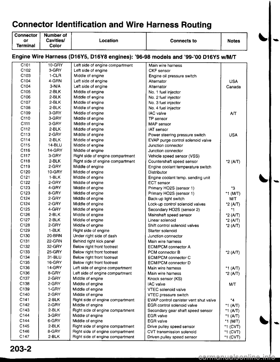
Connector ldentification and Wire Harness Routing
Connector
or
Terminal
Number ot
Cavities/
Golor
LocationConnects toNotes
Engine Wire Harness (Dl6Y5, D16Y8 engines): '96-98 models and '99;00 D16Y5 dM/T
c101
c102
c 103
c104
Q104
c105
c106
c107
cl 08
cl09
cl10
c1l1
cl'12
c113
c114
c'115
c116
c'117
c 118
c119
c120
c121
c122
c123
c123
c124
Q124
c125
c 126
c127
c128
c129
c130
c131
cl32
c 134
c135
c136
c137
c138
c139
c'140
c141
c142
c143
c144
c'|44
c145
c146
c147
1O-GRY
3.GRY
1-CLR
4-GRN
3-N/A
2-BLK
2-BLK
2-BLK
2-BLK
3-GRY
3-GRY
3-GRY
2.BLK
2.GRY
2-BLK
14-BLU
14-GRY
3.GRY
2-BLK
2-GRY
1O-GRY
1.BLK
2.GRY
4-GRY
8-GRY
2-GRY
2.GRY
4-GRY
2.BLK
2.BLK
2-GRY
1.BLK
2O.BRN
22.GRN
32.GRY
25.GRY
31-BLU
16.GRY
14-GRY
8.GRY
2-GFIY
2.GRY
1-GRY
2-GRY
2-BLK
2-GRY
2.BLK
3-GRY
6-GRY
2.BLK
8-GRY
2-BLK
Left side of engine compartment
Left side of engine
Middle of engineI att .i.la ^f an^i^6
Left side ot engine
Middle of engine
Middle of engine
Middle of engine
Middle of engine
Middle of engine
[,liddle of engine
Middle ot engine
Middle ot engine
Middle of engine
Middle of engine
Middle of engine
l\,liddle of engine
Right side of engine compartment
Right side of engine compartment
Middle ot engine
Middle of engine
Middle of engine
Middle of engine
l\,liddle of engine
Nliddle of engine
Middle ot engine
Middle of engine
Middle ot engine
Middle of engine
Middle of engine
Nliddle of engine
Right side of engine
Under right side of dash
Behind right kick panel
Below right front footrest
Below right front footrest
Below right front footrest
Below right front tootrest
Left side ot engine compartment
Left side of engine compartment
Middle of engine
liliddle ot engine
Middle of engine
Nriddle ol engine
Right side of engine compartment
Middle ol engine
Right side of engine compartment
Middle of engine
N,liddle of engine
Right side of engine compartment
Right side of engine compartment
Bight side of engine compartment
Main wire harness
CKF sensor
Engine oil pressure switch
Alternator
Alternator
No. 1 fuel injector
No. 2 fuel injector
No. 3 fuel injector
No.4 fuel injector
IAC valve
TP sensor
MAP sensor
IAT sensor
Power steering pressure switch
EVAP purge control sol€noid valve
Junction connector
Junction connector
Vehicle speed sensor (VSS)
Countershatt speed sensor
Engine coolant temperature switch
Distributor
Engine coolant temp. sending unit
ECT sensor
Primary HO2S (sensor '1)
Primary HO2S (sensor '1)
Back-up light switch
Lock-up control solenoid valves
Secondary HO2S (sensor 2)
lvlainshafl speed sensor
Lanear solenoid
Shift control solenoid valves
Starter solenoid
Junction connector
Main wire harness
ECM/PCM connector A
PCM connector B
ECM/PCNI connector C
ECM/PCl\,,| connector D
Main wire harness
Maln wire harness
Knock sensor (KS)
IAC valve
VTEC solenoid valve
VTEC pressure switch
EVAP control canister vent shut valv€
EGR control solenoid valve
Secondary gear shatt speed sensor
EGR valve
EGR valve
Drive pulley speed sensor
CVT transmission solenoid
Driven pulley speed sensor
USA
Canada
AlT
USA
'2( tr\
'3
-1 (M/r)
t\4/T'2 (Anl'1
'2 (An)'2 (Nr)'2 (AtT)
'2 (Atr)
-1 (An)-2( fi|
M/T
.1 (Arr).1 (A,T)"1 (A/r)-1 (M/r).1 (CVT),1 (cw)'1 (CVT)
203-2
Page 2145 of 2189
Connector ldentification and Wire Harness Routing
Connector
or
Terminal
Number of
Cavities/
Color
LocationConnects toNotes
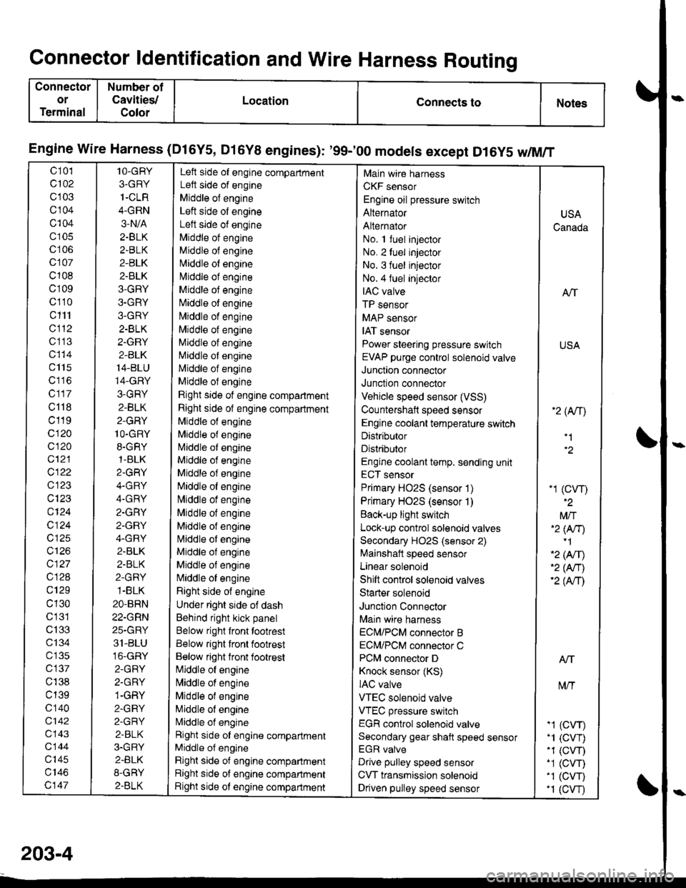
Engine wire Harness (Dl6Y5, Dl6Y8 engines): '99-'00 models except D16y5 w/M/T
c 101
c102
c103
cl04
c104
c105
c106
c107
c108
c109
c110
c111
cl12
c1 13
c115
c117
c118
c119
c120
c120
c12'l
cl22
c123
c124
c124
c125
c126
c127
c128
c129
c130
c'131
c133
ct34
c 135
c137
c138
c139
c 140
c142
c143
c144
c'|45
c147
1O-GRY
3.GRY
1-CLR
4-GRN
3-N/A
2.BLK
2.BLK
2-BLK
2.BLK
3-GRY
3-GRY
3.GRY
2-BLK
2.GRY
2-BLK
14-BLU
14-GRY
3-GRY
2-BLK
2-GRY
1O-GRY
8.GRY,1-BLK
2.GRY
4.GRY
4.GRY
2.GRY
2.GRY
4.GRY
2.BLK
2-BLK
2-GRY
1-BLK
2O-BRN
22-GRN
25-GRY
31-BLU
16-GRY
2-GRY
2.GRY
1-GRY
2-GRY
2-GRY
2-BLK
3.GRY
2.BLK
8-GRY
2.BLK
Left side of engine compartment
Left side of engine
Middle of engine
Left side of engine
Left side of engine
Middle ot engine
Middle of engine
N,liddle of engine
l\4iddle of engine
Middle of engine
Niliddle of engine
N,,liddle of engine
Middle of engine
Middle of engine
Middle of engine
Middle of engine
Middle of engine
Rjght side of engine compartment
Right side of engine compartment
Middle of engine
Mlddle of engine
l\4iddle of engine
Middle of engine
Middle of engine
[iliddle of engine
lvliddle of engine
Middle of engine
Middle of engine
l\4iddle of engine
Middle ol engine
Middle of engine
N,liddle of engine
Right side of engine
Under right side of dash
Behind right kick panel
Below right front tootrest
Below right front footrest
Below right lront footrest
[iliddle of engine
l\,liddle of engine
Middle of engine
Middle of engine
L4iddle of engine
Right side of engine compartment
Middle of engine
Right side of engine compartment
Right side of engine compartment
Right side ot engine compartment
Main wire harness
CKF sensor
Engine oil pressure switch
Alternator
Alternator
No. 1 fuel injector
No. 2luel injector
No. 3 fuel injector
No.4 fuel injeclor
IAC valve
TP sensor
MAP sensor
IAT sensor
Power steering pressure switch
EVAP purge control solenoid valve
Junction connector
Junction connector
Vehicle speed sensor (VSS)
Countershaft speed sensor
Engine coolant temperature switch
Distributor
Distributor
Engine coolant temp. sending unit
ECT sensor
Primary HO2S (sensor 1)
Primary HO2S (sensor 1)
Back-up light switch
Lock-up control solenoid valves
Secondary HO2S (sensor 2)
Mainshait speed sensor
Linear solenoid
Shift control solenoid valves
Starter solenoid
Junction Connector
Main wire harness
ECN4/PCM connector B
ECM/PCM connector C
PCM connector D
Knock sensor (KS)
IAC valve
VTEC solenoid valve
VTEC pressure switch
EGR control solenoid valve
Secondary gear shaft speed sensor
EGR valve
Drive pulley speed sensor
CVT transmission solenoid
Driven pulley speed sensor
USA
Canada
ATT
USA
'2 (An\
'1
-1 (cw)
Mft'2 lNr)'1
'2 (Afil'2 (An)'2 (Anl
Atf
t\4/T
-1 (CVr)'1 (CVT).1 (CW)-1 (CVT)'1 (CVT).1 (cw
203-4
Page 2161 of 2189
Connector ldentification and Wire Harness Routing
Connector
or
Terminal
Number ol
Cavities/
Color
LocationConnects toNotes
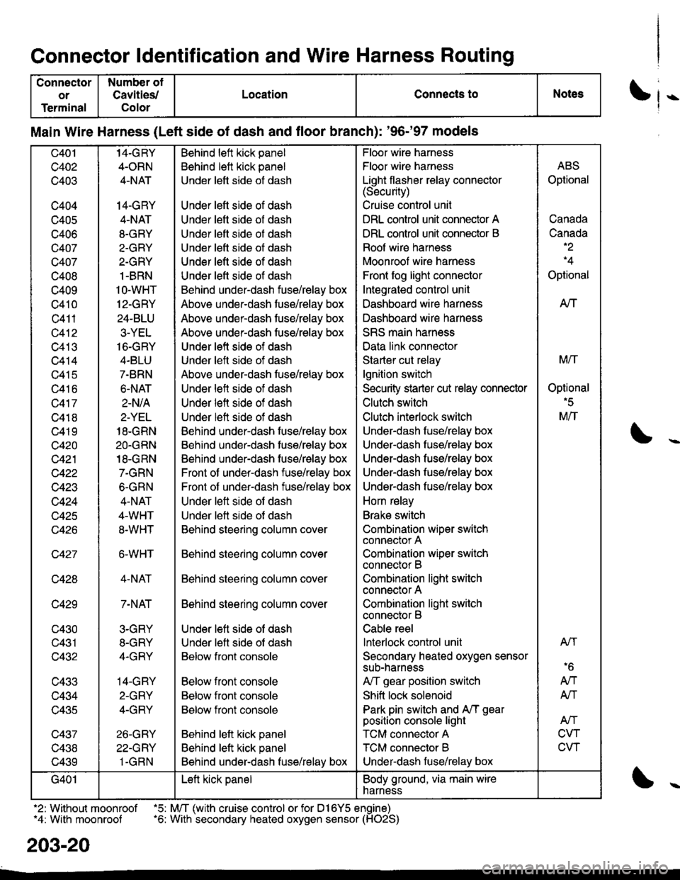
Main Wire Harness (Left side of dash and floor branch): '96-'97 models
c401
c402
c403
c404
c405
c406
c407
c407
c408
c409
c410
c411
c412
c413
c414
c415
c416
c417
c418
c419
c420
c421
c422
w+4J
c424
c425
c427
c428
c429
c430
c431
c432
c433
c434
lJ+OC
c437
v+.to
c439
14-GRY
4-ORN
4-NAT
14-GRY
4-NAT
8-GRY
2-GRY
2-GRY
1-BRN
1O-WHT
12-GRY
24-BLU
3-YEL
16-GRY
4.BLU
7-BRN
6.NAT
2-N/A
2-YEL
18-GRN
2O.GRN
18-GRN
7-GRN
6-GRN
4-NAT
4-WHT
8.WHT
6-WHT
4-NAT
7-NAT
3-GRY
8-GRY
4.GRY
14-GRY
2-GRY
4-GRY
26-GRY
22-GRY
1-GRN
Behind left kick panel
Behind left kick panel
Under left side ot dash
Under left side of dash
Under left side of dash
Under left side of dash
Under lett side ot dash
Under left side of dash
Under left side of dash
Behind under-dash fuse/relay box
Above under-dash fuse/relay box
Above under-dash fuse/relay box
Above under-dash fuse/relay box
Under left side of dash
Under left side of dash
Above under-dash fuse/relay box
Under left side of dash
Under left side of dash
Under left side of dash
Behind under-dash fuse/relay box
Behind under-dash fuse/relay box
Behind under-dash fuse/relay box
Front of under-dash iuse/relay box
Front of under-dash fuse/relay box
Under left side of dash
Under left side of dash
Behind steering column cover
Behind steering column cover
Behind steering column cover
Behind steering column cover
Under left side of dash
Under lett side ot dash
Below front console
Below front console
Below front console
Below front console
Behind lett kick panel
Behind left kick panel
Behind under-dash fuse/relay box
Floor wire harness
Floor wire harness
Light flasher relay connector(Security)
Cruise control unit
DRL control unit connector A
DRL control unit connector B
Roof wire harness
Moonroof wire harness
Front fog light connector
Integrated control unit
Dashboard wire harness
Dashboard wire harness
SRS main harness
Data link connector
Starter cut relay
lgnition switch
Security starter cut relay conneclor
Clutch switch
Clutch interlock switch
Under-dash fuse/relay box
Underdash fuse/relay box
Under-dash fuse/relay box
Under-dash fuse/relay box
Underdash fuse/relay box
Horn relay
Brake switch
Combination wiper switch
connector A
Combination wiper switch
connector B
Combination light swilch
connector A
Combination light switch
connector B
Cable reel
lnterlock control unit
Secondary heated oxygen sensor
sub-narness
A,/T gear position switch
Shift lock solenoid
Park pin switch and A,/T gear
position console light
TCM connector A
TCM connector B
Under-dash luse/relay box
ABS
Optional
Canada
Canada-2
'4
Optional
AtT
M/T
Optional'5
M/T
Atl
'6
AN
AN
Atf
CVT
CVT
G401Left kick panelBody ground, via main wire
harness
.2: Without moonroof .5: M/T (with cruise control or for D16Y5 engine)"4: With moonroof .6: With secondary heated oxygen sensor (HO2S)
203-20
Page 2163 of 2189
Connector ldentification and Wire Harness Routing
Connector
or
Terminal
Number of
Cavities/
Color
LocationConnects toNotess
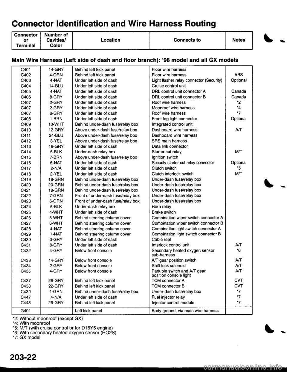
Main Wire Harness (Left side of dash and tloor branch): '98 model and all GX models
c401
c402
c403
c404
c405
c406
Q407
c407
c407
c408
c409
c410
c411
c412
c413
c414
c415
c416
c417
c418
c419
c420
c421
c422
c423
c424
c425
c426
c427
c428
c429
c430
c431
c432
c433
c434
c435
c437
c438
c439
c447
c448
14-GRY
4.ORN
4-NAT
14-BLU
4-NAT
8.GRY
2.GRY
2-GRY
6.GRY
1-BRN
1O-WHT
12-GRY
24-BLU
3-YEL
16-GRY
5-BLK
7-BRN
6-NAT
2.N/A
2.YEL
18.GRN
2O.GRN
18-GRN
7.GRN
6.GRN
5-BLK
4.WHT
8-WHT
6-WHT
4-NAT
7-NAT
3.GRY
8-GRY
4-GRY
14-GRY
2.GRY
4.GRY
26.GRY
22-GRY
1.GRN
4-N/A
26-GRY
Behind lett kick panel
Behind lett kick panel
Under lett side of dash
Under lett side ol dash
Under lett side of dash
Under left side of dash
Under lett side of dash
Under lett side ot dash
Under left side of dash
Under l€ft side of dash
Behind undsr-dash tuse/rBlay box
Above under-dash tuse/relay box
Above under-dash tuse/relay box
Above under-dash fuse/relay box
Under lett side of dash
Under-dash relay box
Above under-dash tuse/relay box
Under left side of dash
Under lett side of dash
Under left side of dash
Behind under-dash tuse/relay box
Behind under-dash tuse/relay box
Behind under-dash tuse/relay box
Front of under-dash tuse/relay box
Front ol under-dash fuss/relay box
Under-dash relay box
Under lett side ot dash
Behind steering column cover
Behind steering column cover
Behind steering column cover
Behind steering column cover
Und€r left side of dash
Under lett side of dash
Below front console
Below front console
Below front console
Below front console
Behind left kick panel
Behind left kick panel
Behind under-dash fuse/relay box
Under lett side of dash
Behind left kick panel
Floor wire harness
Floor wire harness
Light tlasher relay connector (Security)
Cruise control unit
DRL control unit connector A
DRL control unit connector B
Boot wire harnsss
Moonroof wire harness
Boof wire harness
Front fog light connector
Integrated control unit
Dashboard wire harness
Dashboard wire harness
SRS main harness
Data link connector
Starler cut rslay
lgnition switch
Security strarter cut relay connector
Clutch switch
Clutch interlock switch
Under-dash fuse/relay box
Under-dash fuse/relay box
Under-dash fuso/rolay box
UndeFdash fuse/relay box
Under-dash fuse/relay box
Horn relay
Brake switch
Combination wiper switch connector A
Combinalion wiper srvitch connector B
Combinalion light switch connector A
Combinalion lighi swilch connector B
Cable reel
lnterlock control unil
Secondary heated oxygen sensorsuD-narness
A,/T gear position switch
Shift lock solenoid
Park pin switch and A/T gearposition console light
TCM connector A
TCM connector B
Underdash lus€/relay box
Fuel injector relay
Injector control module
ABS
Optional
Canada
Canada,2
,4
'7
Optional
AIf
Mtf
Oplional'5
M/T
AN'6
An
A,/T
Alf
CW
CVT'7
'7
'7
G401Left kick panelBody ground, via main wire harness
-2: Without moonroof (except GX)-4: With moonroof'5: M/T (with cruise control or for D16Y5 engine)'6: With secondary heated oxygen sensor (H02S)t7: GX model
203-22