1996 HONDA CIVIC D 16
[x] Cancel search: D 16Page 969 of 2189
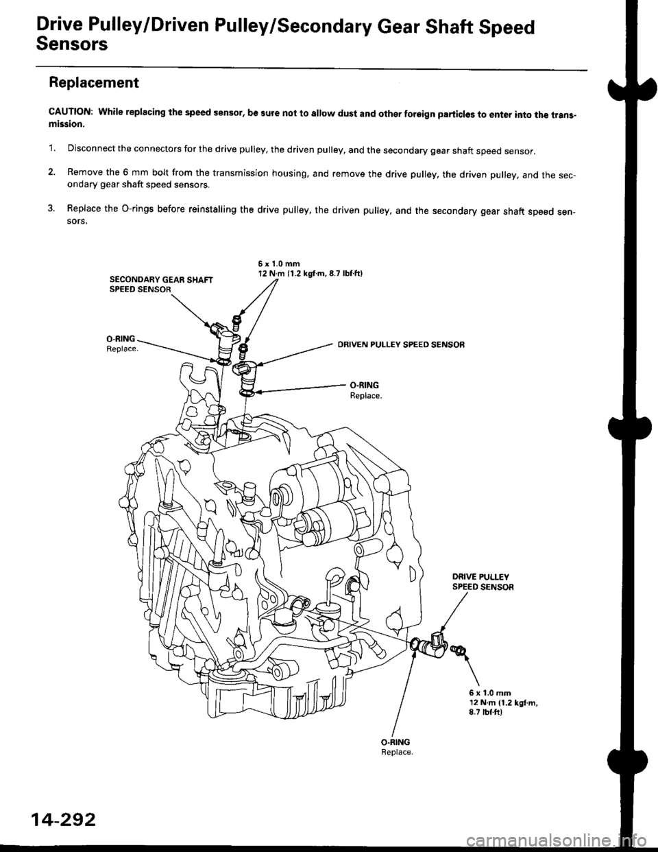
Drive Pulley/Driven Pulley/Secondary Gear Shaft Speed
Sensors
Replacement
CAUTION: While replacing the speed sensor, be sure not to allow dust and other foreign parliclos to enter into the trans-mission.
'1. Disconnect the connectors for the drive pulley, the driven pulley, and the secondary gear shaft speed sensor.
2. Remove the 6 mm bolt from the transmission housing, and remove the drive pulley. the driven pulley, and the sec-ondary gear shaft speed sensors.
3. Replace the O-rings before reinstalling the drive pulley, the driven pulley, and the secondary gear shaft sp€ed sen-sors.
6x1.0mm12 N.m (1.2 kgf.m,8.7 lbf.ft)
6x1.0mm12 N.m (1.2 kgt.m,8.7 tbf.ft)
DRIVEN PULLEY SPEED SENSOB
14-292
Page 970 of 2189
Start Clutch Control@
T
Start Clutch Calibration Procedure
NOTE: When the following parts are replaced, the TCM
must memorize the feedback signal for the start clutch
control.
. TCM
. Transmissionassembly
. Stan clutch assembly
. Lower valve bodv assembly
. Engine assembly or overhaul
'96 Model Only
CAUTION: Do not uso this procsdure on'97 - (X) mod-
els or you will damage the transmission. On '97 - 00
models, the TCM or PCM memorizes ths loodback sig'
nals when you drive the vehicle.
1. Engage the parking brake, and block the front
wheels securely.
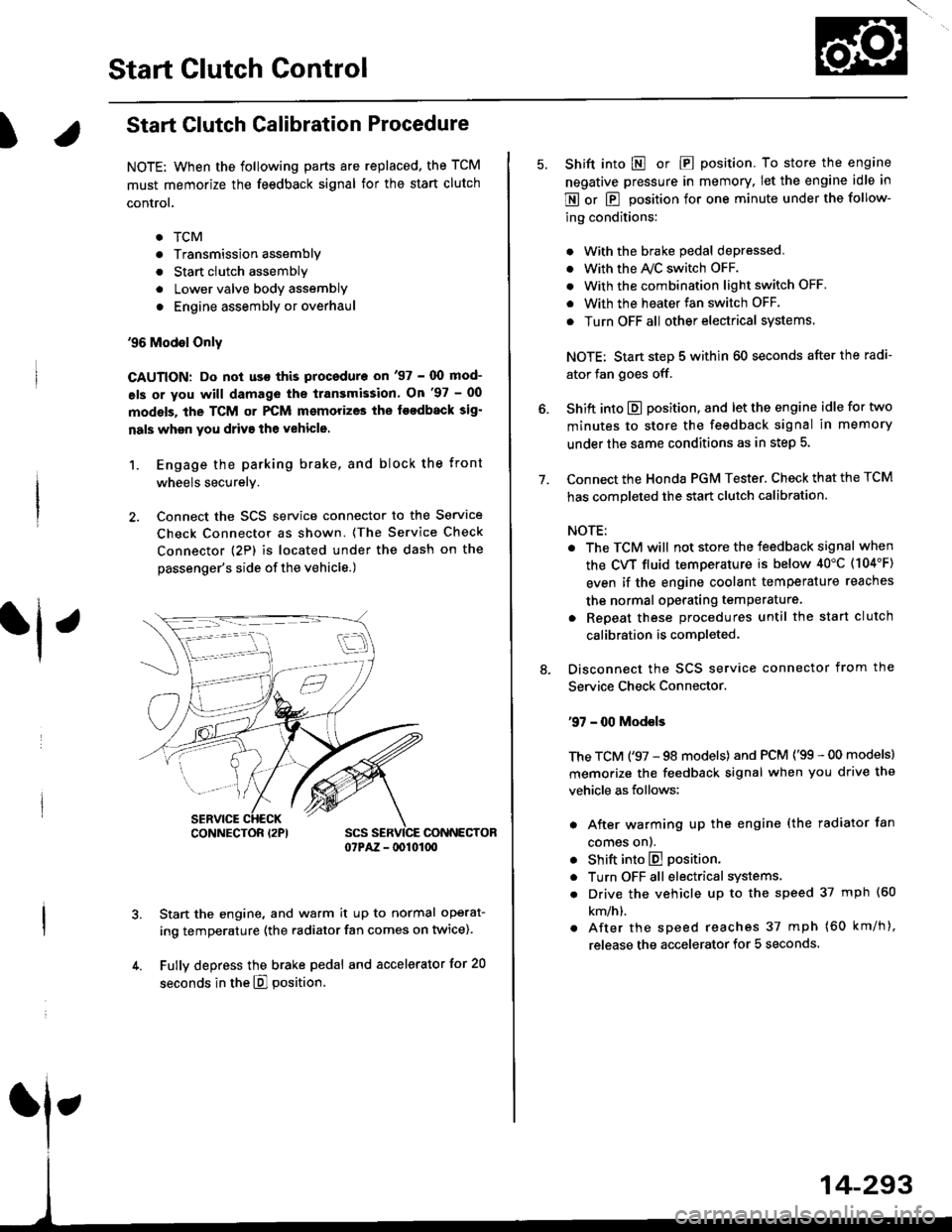
2. Connect the SCS service connector to the Service
Check Connector as shown. (The Service Check
connector (2P) is located under the dash on the
passenger's side of the vehicle.)
CONNECTOR07PAZ - lDl01(xt
Start the engine, and warm it up to normal operat-
ing temperature (the radiator fan comes on twice).
Fully depress the brake pedal and accelerator for 20
seconds in the E] position.
rl ,
CONNECTOR I2PI
14-293
7.
Shift into E o|. E position. To store the engine
negative pressure in memory. Iet the engine idle in
E or E position for one minute under the follow-
ing conditions:
. With the brake pedal depressed,
. with the y'\/c switch oFF.
. With the combination light switch OFF.
. With the heater fan switch OFF.
. Turn OFF all other electrical systems
NOTE: Start step 5 within 60 seconds after the radi-
ator fan goes off.
Shift into E position, and let the engine idle for two
minutes to store the feedback signal in memory
under the same conditions as in step 5.
Connect the Honda PGM Tester. Check that the TCM
has completed the start clutch calibration.
NOTE:
. The TCM will not store the feedback signal when
the CVT fluid temperature is below 40"C (104'F)
even if the engine coolant temperature reaches
the normal operating temperature.
. Repeat these procedures until the start clutch
calibration is completed-
Disconnect the SCS service connector from the
Service Check Connector.
'97 - 00 Models
The TCM ('97 - 98 models) and PCM ('99 - 00 models)
memorize the feedback signal when you drive the
vehicle as follows:
. After warming up the engine (the radiator fan
comes onl.
. Shift into E position.
. Turn OFF all electrical systems,
. Drive the vehicle up to the speed 37 mph (60
km/h).
. After the speed reaches 37 mph (60 km/h),
release the accelerator for 5 seconds.
Page 971 of 2189

Symptom-to-Component Chart
Hydraulic System
*1: Some gear noise is normal in the Lll position due to planetary gear action.
14-294
SYMPTOMCheck these items on the PBOBABLE CAUSE List
Engine runs, but vehicle does not move in any position.'t,2,3,4,5,6,7,8,9, 10, 20, 34, 35, 36, 38, 41
Vehicle does not move in @, [. p positions.10,11, 12, 20, 41
Vehicle does not move in E position.5, 'to, 11, 12, 17, 1A, 19, 20,39, 41
No shift to higher ratio,9, 13, 14. 15, 16,35,37,40
Poor acceleration.9, 13,'�t4,'t5,16. 20, 35, 37, 38, 40
Flares on moving.9,'t0, 20, 2't, 35, 36, 38, 40, 42
Excessive shock when depressing and releasing.^^alA/.r^r ^A.1. I9, 10, 20, 2'1, 35, 36, 3A, 42
No engine braking.9,20,21,35,36,38
Vehicle does not accelerate in lll position.9, 17, 18, 19, 20. 35, 36, 38
Vehicle moves in E position.
(Shift cable adjustment is proper).10, 22,23
Late shift from N position to E position, and from Eposition to E position.'10,11, 12,22, 41
Late shift from E position to E position. and from Eposition to N position.1l,'t2, 17, 18,22, 41
Engine stops when shifted to E position from E position.9, 10,20,35,37,34, 42
Engine stops when shifted to E position from I position.9, 18, 19,20,25,26,35,37,38, 42
Noise from transmission in @ position.rl5, 17, 18, 't9,25,26
Excessive idle vibration.2,3,4,21,24
Noise from transmission in @ and @ positions.2,3, 19,24,25,2A
Hunting engine speed.16, 35, 37, 38
Vibration in all position.8, 2a
Shift lever does not operate smoothly.11,29, 4'l
Transmission will not shift into lll position or transmis-
sion cannot be removed from E position.11 , 29, 30, 31, 32,33
Vehicle does not accelerate to more than a certain speed.9, 10, 14, 15,'t6,20,35,37
Excessive shock on starting off.38, 42
Flares on accelerating at low speed.20, 21 ,38, 42
Excessive vibration in E, E, tr, E positions.20,21,38, 42
Low engine speed in E. E. tr. E positions.20,21,38,42
Stall speed high.10,20,38
Stall speed low.9, 20, 27 ,37 , 38
Judder on starting off.20, 43
Page 972 of 2189
t.
rl,
fl,
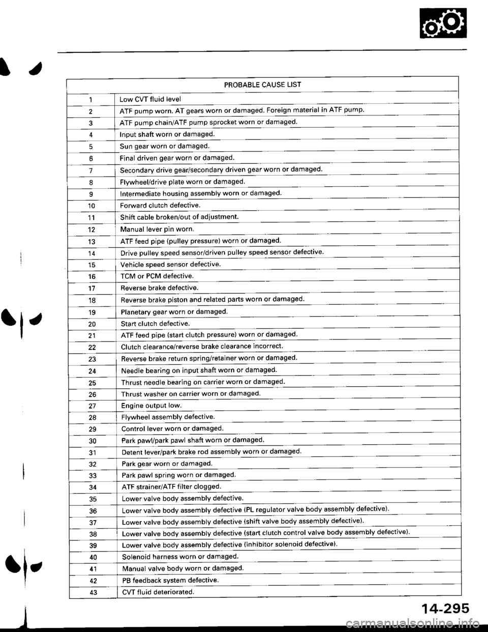
PROBABLE CAUSE LIST
Low CVT fluid level
ATF pump worn. AT gears worn or damaged. Foreign material in ATF pump.
ATF pump chain/ATF pump sprocket worn or damaged.
Input shaft worn or damaged.
Sun gear worn or damaged.
Final driven oear worn or damaqed,
Secondary drive gear/secondary driven gear worn or damaged-
5
6
1
8Flywheel/drive plate worn or damaged.
Intermediate housing assembly worn or damaged.9
'10Forward clutch defective.
Shift cable broken/out of adiustment.
M"nu"t t"uffi
ATF feed pipe (pulley pressure) worn or damaged.
Vchiclc speed sensor defective.
TCM or PCM defective.
Reverse brake detective.
1'�r
't2
13
14
16
'11
'18
1qPlanetary gear worn or damaged.
Sta rt clutch defective.
ATF feed pipe (start clutch pressure) worn or damaged
20
t't
Clutch clearance/reverse brake clearance incorrect.
23Reverse brake return spring/retainer worn or damaged
24Needle bearing on input shaft worn or damaged.
25Thrust needle bearing on carrier worn or damaged.
Thrust washer on carrier worn or damaged.
Enoine outout low.------------------------
Flvwhcel assemblv defective.
Control lever worn or damaged.
Park pawl/park pawl shaft worn or damaged
Detent lever/park brake rod assembly worn or damaged
27
29
30
32Park gear worn or damaged.
Park pawl spring worn or damaged.
ATF strainer/ATF filter clogged.
Lower valve body assembly defective.
Lower valve bodv assemblv defective (PL regulator valve body assembly defective)'
33
34
50
Lower valve bodv assembly defective (shift valve body assembly defective).
Lower valve bodv assemblv defective (start clutch control valve body assembly defective)'
39Lower valve bodv assemblv defective {inhibitor solenoid defective}
40Solenoid harness worn or damaged.
Manual valve body worn or damaged.
PB feedback system defective.
CVT fluid deteriorated.
41
43
14-295
Page 973 of 2189
Road Test
NOTE: Warm up the engine to normal operating temperature (the radiator fan com6s on).
1. Apply the parking brake and block the wheels. Start the engine, then shift to the E position while depressing the
brake pedal. Depress the accelerator pedal and release it suddenly. The engine should not stall.
2. Test in E position
Park the vehicle in a slope (approx. 16'). apply the parking brake, and shift into E position. Release the brake; the
vehicle should not move.
3. Test-drive the vehicle on a flat road in the position shown in the table. Check that the engine speeds meet the approx-imate vehicle speeds shown in the table.
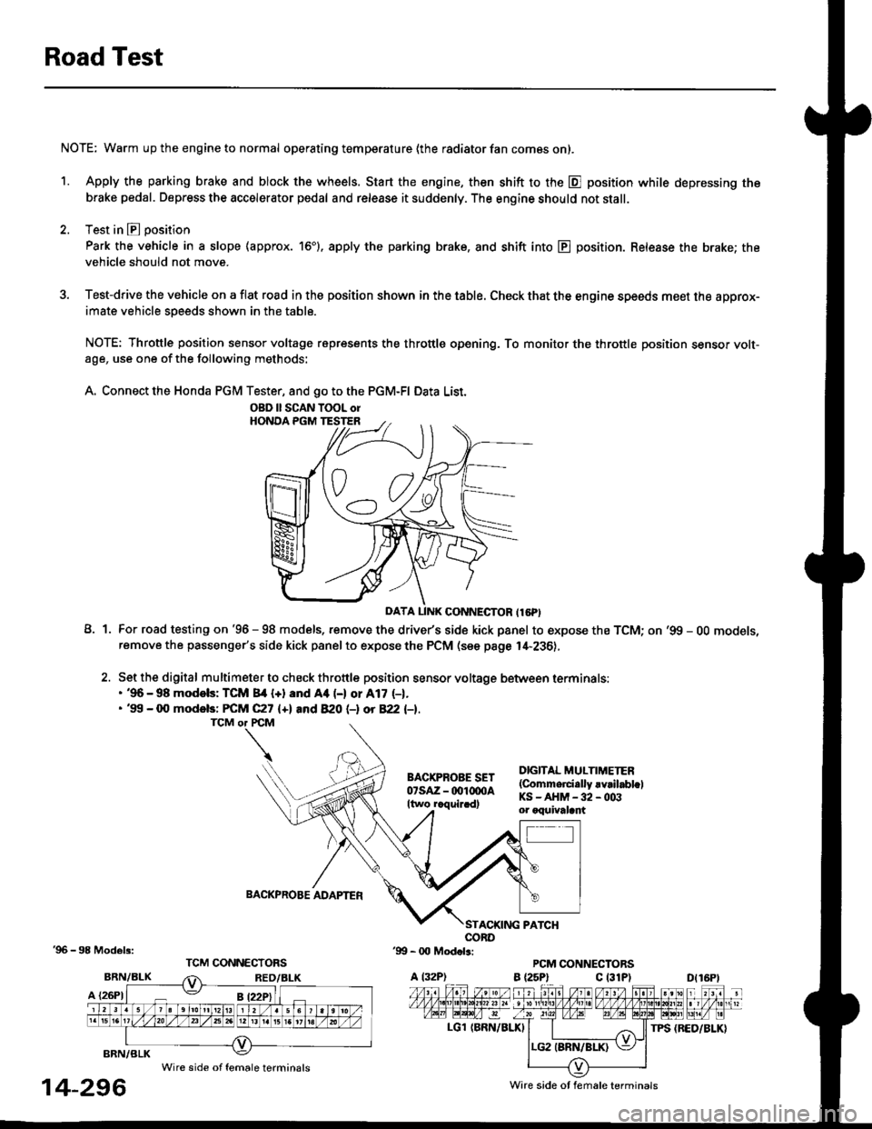
NOTE: Throttle position sensor voltage represents the throttle opening. To monitor the throttle position sensor volt-age, use one of the following methods:
A. Connect the Honda PGM Tester, and go to the PGM-FI Data List.
A1For road testing on '96 - 98 models, remove the drive/s side kick panel to expose the TCM; on '99 - OO models,remove the passenger's side kick panel to expose the PCM (see page l,[-236),
Set the digital multimeter to check throttle position sensor voltage between terminals:. '96 - 98 modols: TCM 84 {+} and Aa (-) or A17 (-1.. '99 - 0O models: FCM C27 {+l and 820 (-l ot 822 l-1.
DIGITAL MULTIMETER(Commerci.lly rvrilabl.lKS-AHM-32-003or oquivalant
BACKPROBE ADAPTER
BRN/BLK
A {26P1
TPS {BED/BLK}
'96 - 98 Models:
BRN/BLK
14-296
OBD ll SCAN TOOL orHONOA PGM TESTER
D{16Pt
Ware side ot female terminals
Wire side of female terminals
Page 974 of 2189

o @ position: Engino Speed rPm
Throttle Opening
Vehiclo Speed
-25 mph l/() km/h) | 37 mph {60 km/h) | 62 mph {100 km/h}
Throttle position sensor voltage: 0.75 V1,250 - 1,650
Throttle position sensor voltage: 2'25 V2,500 - 3,1002,650 - 3,2502,700 - 3,300
Throttle position sensor voltage; 4 5 V
Full throttle position3,950 - 4,5504,650 - 5,2505,200 - 5,800
o $l position: Engine Speed rPm
Throttle Oponing
Vehicle Spoed
2s mph (40 km/hl | 37 mph (60 km/hl | 62 mph {r00 km/h}
Throttle position sensor voltage: 0.75 V1,800 - 2,2002,200 - 2,8003,550 - 4,150
Throttle Dosition sensor voltage: 2.25 V2,950 - 3.5503,250 - 3,8504,050 - 4,650
Throftle position sensor voltage: 4.5 v
Full throftle position4,100 - 4,7005,100 - 5,7005,900 - 6,500
o E position: Engin€ Sp6ed rPm
Throttle Oponing
Vehiclo Spoed
25 mph (40 km/hl | 37mPh{60km/h) J 62 mph 1100 km/h}
Throttle Dosition sensor voltage: 0.75 V3,100 - 3,7003,650 - 4,2504,450 - 5,050
Throttle position sensor voltage; 2.25 V3,500 - 4,1004,050 - 4,6504,800 - 5,400
Throttle position sensor voltage: 4.5 V
Fullthrottle position4,100 - 4,7005,100 - 5.7005,900 - 6,500
14-297
Page 975 of 2189
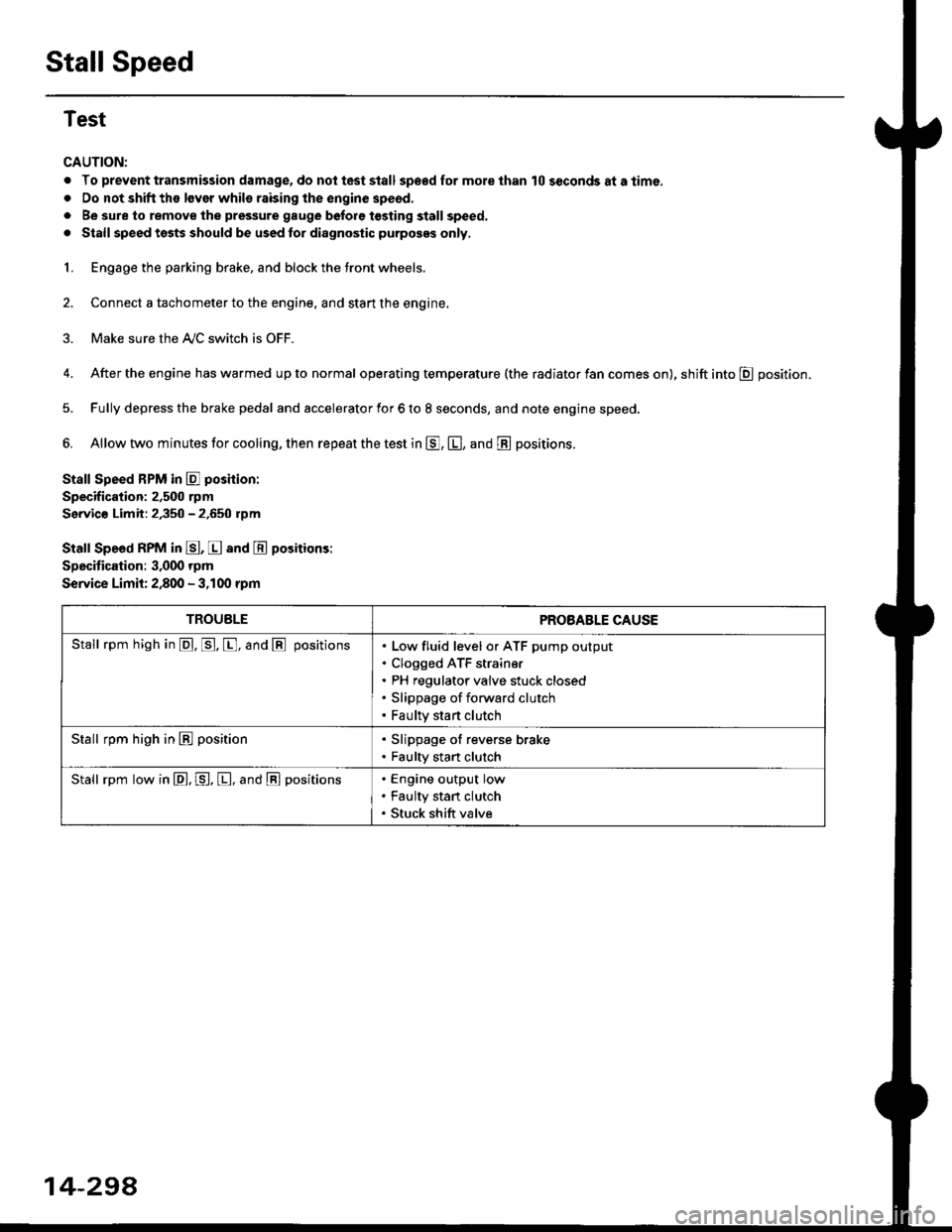
Stall Speed
Test
CAUTION:
. To prevent transmission damage, do not test stall sp€€d for mole than 10 seconds at a time.
. Do not shift the lsver whils raising the engine speod.
. Be sure lo remove the pressure gauge before tosting stall speed.
. Stall speed tssts should be used tor diagnostic purposes only,
1. Engage the parking brake, and block the tront wheels.
2. Connect a tachometer to the engine, and stan the engine.
3. Make sure the A/C switch is OFF.
4. After the engine has warmed up to normal operating temperature (the radiator fan comes on), shift into E position.
5. Fully depress the brake pedal and accelerator for 6 to 8 seconds, and note engine speed,
6. Allow two minutes for cooling, then repeat the test in E, E, and E positions.
Stall Speed BPM in E poshion:
Specification: 2,500 rpm
Servic€ Limit: 2,350 - 2.650 rpm
Stall Speed RPM in E, E and E positions:
Specitication: 3,000 rpm
Service Limit: 2,800 - 3,100 rpm
TROUBLEPROBABLE CAUSE
Stall rpm high in @. p. [, and @ positionsLow fluid level or ATF pump output
Clogged ATF strain€r
PH regulator valve stuck closed
Slippage of forward clutch
Faulty start clutch
Stall rpm high in E position. Slippage of reverse brake. Faulty start clutch
Stall rpm low in E, P, [, and @ positionsEngine output low
Faulty stan clutch
Stuck shift valve
14-294
Page 976 of 2189

Fluid Level
l.Checking/Changing
CAUTION: while chscking and changing, be sure not to
allow dust and other toreign particles to ent€l inlo the
transmission.
Checking
NOTE: Check the fluid level with the engine at normal
operating temperature (the radiator fan comes on).
'1. Park the vehicle on the level ground. Turn oft the
engrne.
2. Remove the dipstick (yellow loop) from the trans-
mission, and wipe lt with a clean cloth.
NOTE: Check the transmission fluid 50 to 90 sec-
onds after shutting off the engine.
3. Insert the diDstick into the transmission.
DIPSTICK (YELLOW LOOPI
Remove the dipstick and check the fluid level.
should be between the uDDer and lower mark.DIPSTICK
5. lf the level is below the lower mark, add fluid into
the filler hole to bring it to the upper mark. Use
Genuine Honda CW Fluid only.
6. Insert the dipstick into the transmission.
14-299
Changing
1. Bring the transmission up to normal operating tem-
perature (the radiator fan comes on) by driving the
vehicle. Park the vehicle on the level ground, and
turn off the engine.
2. Bemove the drain plug, and drain the CVT fluid.
NOTE| lf a cooler flusher is to be used, see page 14-
352 and 14-353.
Reinstall the drain plug with a new sealing washer,
then refill the transmission with Genuine Honda
CVT Fluid to the upper mark on the dipstick.
Automatic Transmission Fluid CaPacity:
3.9 i (4.r US qt. 3.4 lmp qt) 8t chlnging
6.4 I (6.8 US qt, 5.6 lmp qt) 8t ov€lhaul
Rscommended Automatic Transmission Fluid:
Genuine Honda CVT Fluid-
Use Genuine Honda CW fluid only. Using other flu-
ids can affect transmission operation and may
reduce transmission liJe.
Change Interval:
Normal Condition: 30, 000 miles 148,000 km)
Severe Condition: 30,000 miles (48,000 km), but it
you drive at high sPeeds in high
t90"F (32'C) and abovol temper-
atures, the ttansmission fluid
should be changed evsrY 15,000
miles 124,000 km).
{-]lr
ORAIN PLUG18 x 1.5 mma9 N.7n (5.0 kgl.m, 36 lb{'ftl
SEALING WASHERReplace.