1996 HONDA CIVIC power win
[x] Cancel search: power winPage 2028 of 2189
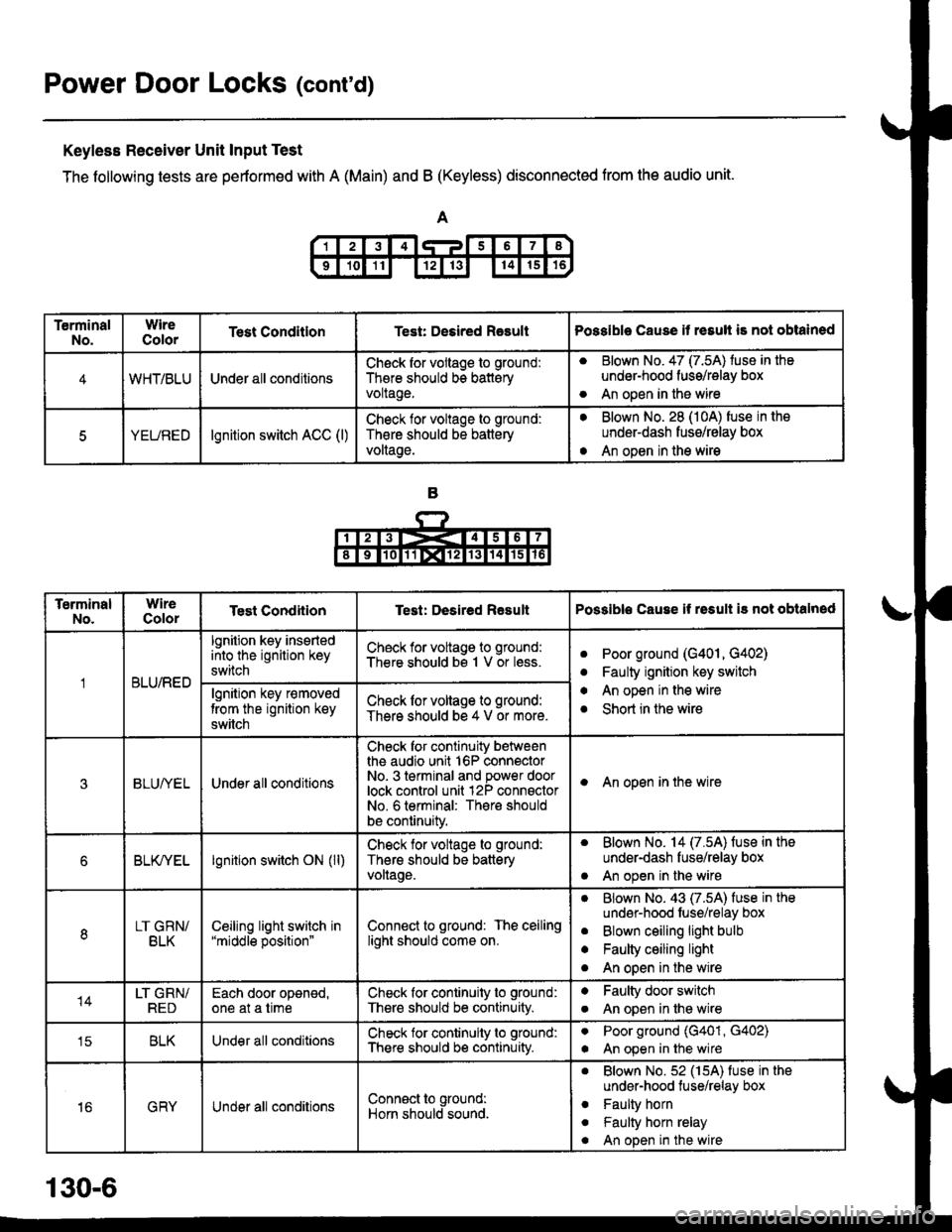
Power Door Locks (cont'd)
Keyless Receiver Unit Input Test
The following tests are pertormed with A (Main) and B (Keyless) disconnected from the audio unit.
TerminalNo.WireColorTest ConditlonTest: Desired RasultPossible Cause it resull is not obtained
4WHT/BLUUnder all conditionsCheck for vollage to ground:
There should bs batteryvoltage.
aBlown No. 47 (7.5A) tuse in the
under-hood fuss/relay box
An open in the wireo
5YEUREDlgnition switch ACC (l)Check lor voltage to ground:
Th€re should be battery
voltage.
aBlown No. 28 (10A) fuse in the
underdash fusg/relay box
An open in the wirea
TerminalNo.WireColorTest CondiiionTest: Desired ResultPossible Cause if rssult i3 not obtalned
BLU/RED
lgnition key insertedinto the ignition key
switch
Check for voltage to ground:
There should bs 1 V or less.aPoor ground (G401, G402)
Faulty ignition key switch
An open in the wire
Short in the wire
a
a
algnition key r€moved
trom the ignition key
switch
Check lor voltage to ground:
There should be 4 V or more.
3BLUI/ELUnder all conditions
Check for continuity betweenthe audio unit 16P connectorNo- 3 terminal and power doorlock control unit 12P connsctorNo. 6 terminal: There should
be continuity.
I An open in the wire
6BLK/YELlgnition switch ON (ll)Check for voltage to ground:
Thers should be batteryvollage.
. Blown No. 14 (7.5A) fuse in the
under-dash fuse/relay box
. An open in the wire
8LT GRN/BLKCeiljng light switch in"middle position"Connect to ground: The ceilinglight should come on.
aBlown No. 43 (7.5A) fuse in the
undsr-hood fuse/relay box
Blown ceiling light bulb
Faulty ceiling light
An open in the wire
a
a
o
14LT GRN/REDEach door oponed,one at a timeCheck for continuity to ground:
There should be continuity.
aFaulty door switch
An open in lhe wirea
tcBLKUnder all conditionsCheck for continuity to ground:
There should b€ continuity.
aPoor ground (G401, G402)
An open in the wirea
16GRYUnder all conditionsConn€ct to ground:
Horn should sound.
. Blown No.52 (15A) fuse in the
under-hood tuse/relay box
. Faulty horn
. Faulty horn relay
. An open in the wire
130-6
Page 2038 of 2189
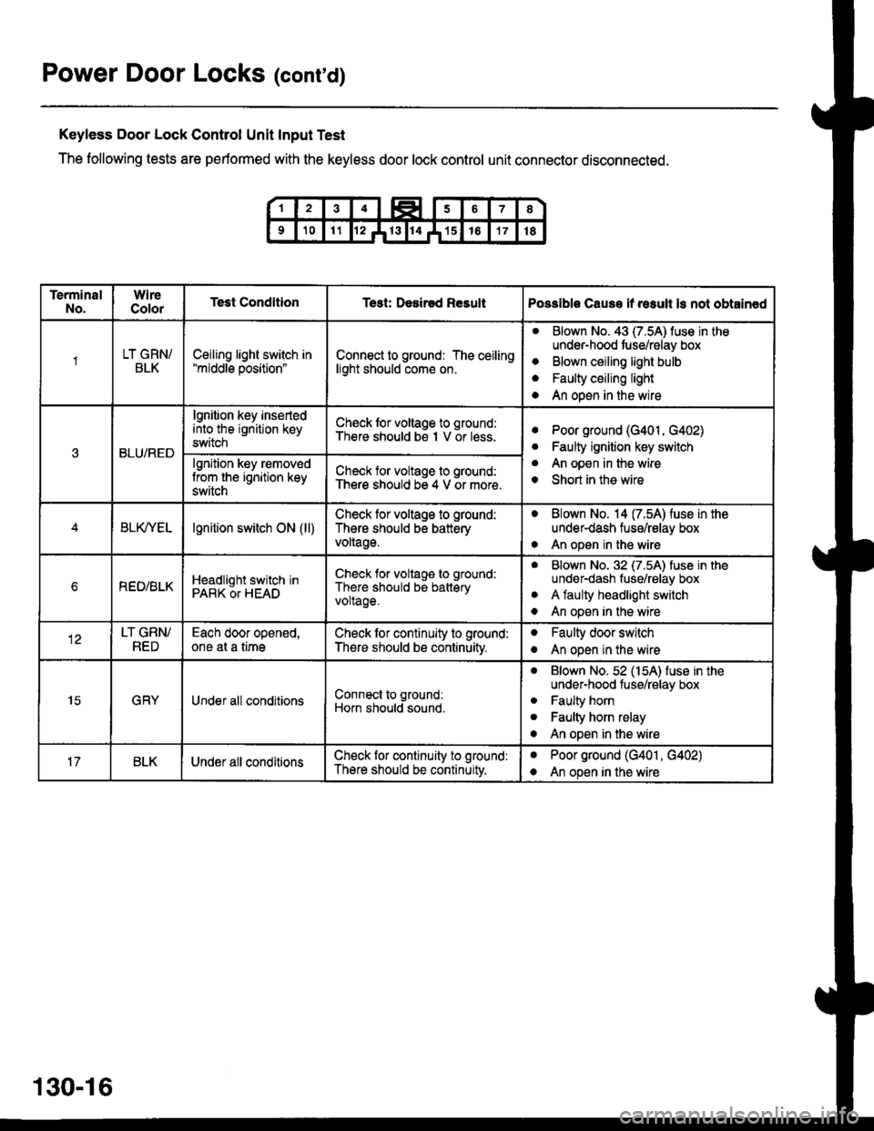
Power Door Locks (cont'd)
Keyless Door Lock Control Unit Input Test
The following tests are performed with the keyless door lock control unit connector disconnected.
TerminalNo.WireColorTest ConditionTest: Desir€d ResultPossible Cause if result ls not obtain€d
1LT GRN/BLKCeiling light switch in"middle position"Connect to ground: The ceilinglight should come on.
aBlown No. 43 (7.5A) luse in theunder-hood tuse/relay box
Blown ceiling light bulb
Faulty ceiling light
An open in the wire
o
a
a
3BLU/RED
lgnition key insertedinto the ignition keyswitch
Ch€ck lor voltage to ground:There should be I V or less.aPoor ground (G401, G402)
Faulty ignition key switch
An open in the wire
Short in the wire
a
a
o
lgnition key removedlrom the ignition keyswitch
Check for voltage to ground:There should be 4 V or more.
BLfiEtlgnition switch ON (ll)Check lor voltage to ground:
There should be batteryvoltage.
. Blown No. 14 (7.54) fuse in theunder-dash fuse/relay box
. An open in the wire
bREO/BLKHeadlight switch inPARK OT HEAD
Check for voltage to ground:
There should be batteryvoltage.
aBlown No. 32 (7.5A) luse in theunder-dash fuse/relay box
A faulty headlight switch
An open in the wire
a
o
LT GRN/RED
Each door opened,one at a timeCheck lor continuity to ground:
There should be continuitv.
oFaulty door switch
An open in the wireo
15GRYUnder all conditionsConnect to ground:
Horn should sound.
. Blown No. 52 (154) fuse in theunder-hood fuse/relay box
. Faulty horn
. Faulty horn relay
o An open in the wire
BLKUnder all conditionsCheck lor continuity to ground:
There should be continuity.
aPoor ground (G401 , G402)
An open in the wirea
130-16
Page 2108 of 2189
-
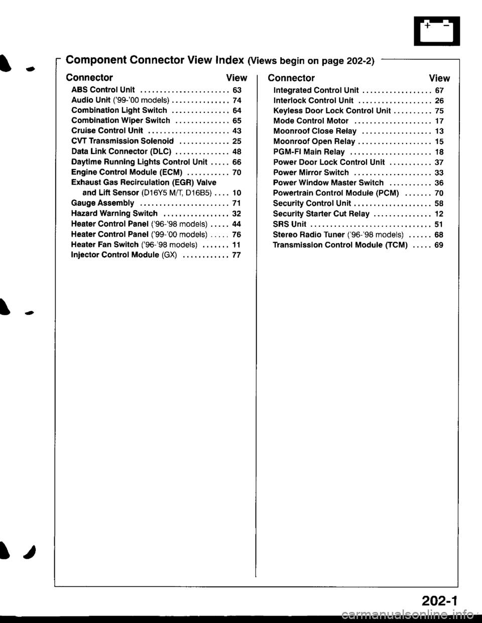
Component Connector View Index (Views begin on page 202-21
Connector View
ABS Control Unit........ ......63
Audio Unit ('99-'00 models) ......74
Combination Light Switch . . . . . . . . . . . . . . . 64
Combination Wiper Switch . . . . . . . . . . . . . . 65
Cruise Control Unit.... .....43
C\TTTransmission Solenoid ............. 25
Data Link Connector (DLC) ..... 48
Daytime Runnlng Lights Control Unit ..... 66
Engine control Module (ECM) ...........70
Exhaust Gas Recirculation (EGR) Valve
and Lift Sensor (D16Y5 Mfl, D1685) . . . . 10
Gauge Assembly .............71
HazardWarnlngSwitch,,. .,,,...,,,,... 32
Heater Control Panel ('96-'98 models) .....44
Heater Control Panel ('99-'00 models) ...., 76
Heater Fan Switch ('96-'98 models) ,,,.... 11
fniector Control Module (GX) ............77
I/
202-1
Connector View
Integrated Control Unit .......,. 67
f nterfock Control Unit .... ...... 26
Keyfess Door Lock Control Unit . . . . , . . . . . 75
Mode Control Motor ... ........'17
Moonroof Close Relay .. .......13
Moonroof Open Relay ... .......15
PGM-FI Main Relay .. .......... 18
Power Door Lock Conlrol Unil ..... ...... 37
Power Mirror Switch .,... ...... 33
Power Window Master Switch .,.........36
Powertrain Control Module (PCM) .......70
Security Control Unit ..., ..,,... 58
Security Starter Cut Belay ... ...,,,....,, 12
SRS Unit ............. 51
Stereo Radio Tuner ('96-'98 models) ...... 68
Transmission Control Module CICM) .....69
Page 2109 of 2189
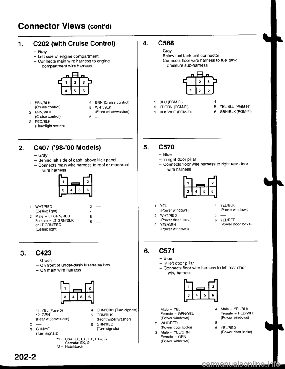
Connector Views (cont'd)
1. C202 (with Cruise Control)
- Gray- Left side ol engine compartment- Connects main wire harness to engine
compartment wre harness
gRN/BLK
(Cruise control)
BRN,ryVHT(Cruise control)
RED/BLK(Headlight switch)
BRN {Cruise conkol)
WHT/BLK(Front wipetwashel)5
4.c568
- Gray- Below Juel tank unit connector- Connects floor wire harness to tuel tank
pressure suo-narness
BLU (PGi.4-Fr)
LT GRN (PGM-FI)
BLl(WHT (PGI\4-FD
YEUBLU (PGM,FI)
GRN/BLK (PGI\,4.FD
4
5
2. C407 ('98-'00 Models)
- Gray- Behind left side ol dash, above kick panel
- Connects main wire harness to roof or moonroo{
wtre harness
WHT/RED(Ceiling light)
l\4ale - LT GRN/REDFemale - LT GRN/BLKor LT GRN/RED(Ceiling light)
5
5.c570
- Blue- In right door pillar- Connects floor wire harness to right rear door
wlre hafness
2
3
YEL(Power windows)
WHT/RED(Power door locks)
YEUGRN(Power wrndows)
YEL/BLK(Power windows)
YEURED(Power door locks)
5
6
3.c423
- Green- On Jront of under-dash tuse/relay box- On main wire harness
*1: YEL (Fuse 3)*2: GRN(Rear wiper/washe4
GRN/YEL(Turn signals)
GRN/ORN {Tu.n signals)
GRN/BLK(Front wiper/washer)
GRN/RED(Turn signals)
5
62
3
*1= USA: tX, EX, HX, DX-V SiCanada: EX, Si*2= Hatchback
202-2
6.c571
- Blue- In lett door pillar- Connects floor wire harness to lett rear door
wlre harness
MaIe _ YELFemale - GBN/YEL(Power windows)
WHT/RED(Power door locks)
Male - YEUGRNFemale - GBN(Power windows)
5
6
N4ale YEUBLKFemale - RED,ryVHT(Power windows)
YEURED(Power door locks)
Page 2113 of 2189
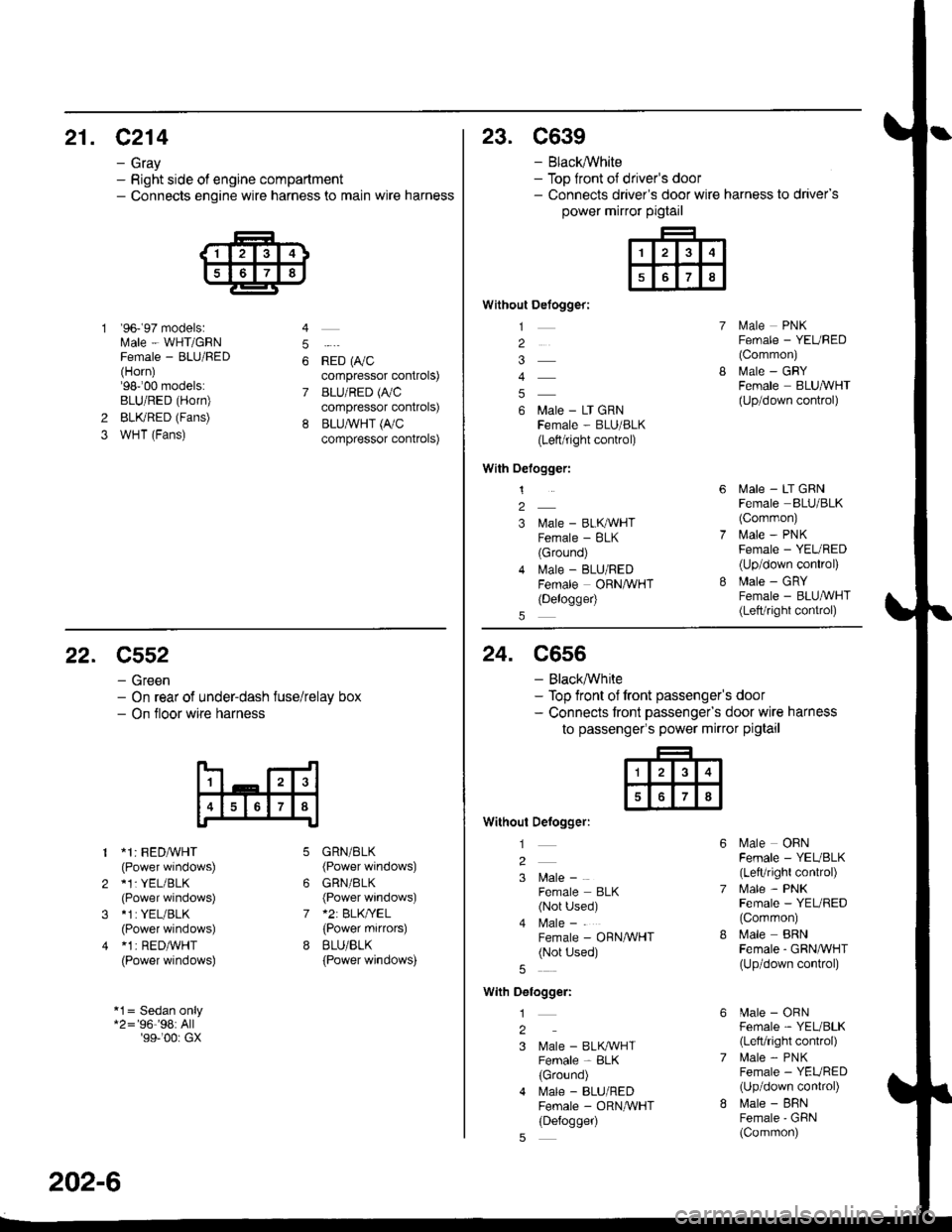
21. C214
- Gray- Right side of engine compartment- Connects engine wire harness to main wire harness
'96- 97 models:Male - WHT/GRNFemale - BLU/FED(Horn)'98-'00 models:BLU/RED (Horn)
BLKRED (Fans)
WHT (Fans)
4
5
6
7
*io t0,,"compressor controls)
BLU/RED (A,/C
compressor controls)
BLU,ryVHT (I'/C
compressor controls)
2
3
23. C639
- Black,ryVhite- Top front ot driver's door- Connects driver's door wire harness to driver's
power mirror pigtail
Without Defogger:
1
2
4
6 Male - LT GRNFema|e - BLU/BLK(Left/right control)
With Oelogger:
1
2
3 l\,lale - BLKAVHTFemale - BLK(Ground)
4 lvlale - BLU/REDFemale ORNAVHT(Delogge4
lvlale PNKFemale - YEURED(Common)
MaIe _ GRYFemale BLUA/VHT(Up/down control)
lvlale - LT GRNFemale BLU/BLK(Corrmon)
i.4ale - PNKFemale - YEURED(Up/down conkol)
Male - GRYFemale - BLU,ryVHT(Lett/right control)
22. C552
- Green- On rear of under-dash fuse/relay box- On tloor wire harness
1 *1: FEDA/VHT(Power windows)
2 *1: YEL/BLK(Power windows)
3 *1:YEL/BLK
(Power windows)
4 *1 | RED/WHT(Power windows)
*1= Sedan only*2='96''98:All'99-'00r GX
6
7
GRN/BLK(Power windows)
GRN/BLK(Power windows)*2: BLK/YEL(Power mifiors)
BLU/BLK
{Power windows)
202-6
24. C556
- Black,ryVhite- Top front of front passenger's door- Connects tront passengefs door wire harness
to passenger's power mirror pigtail
Without Defogger:
l
2
3 l\4ale -
Female BLK(Not Used)
4 l\4ale -
Female - ORN/WHT(Not Used)
With Delogger:
1
2
3 Male - BLK^VHTFemale - BLK(Ground)
4 l\.4ale - BLU/REDFemale - ORNAVHT(Defogger)
Male OBNFemale - YEUBLK(LefVright control)
l\4ale - PNKFemale - YEL/RED(Common)
Male BRNFemale - GRNA/VHT(Up/down conkol)
[.4ale - ORNFemale - YEL/BLK(Left/right control)
lrale - PNKFemale - YEURED(Up/down conkol)
l\,lale - BFNFemale'GFiN(Common)
Page 2116 of 2189
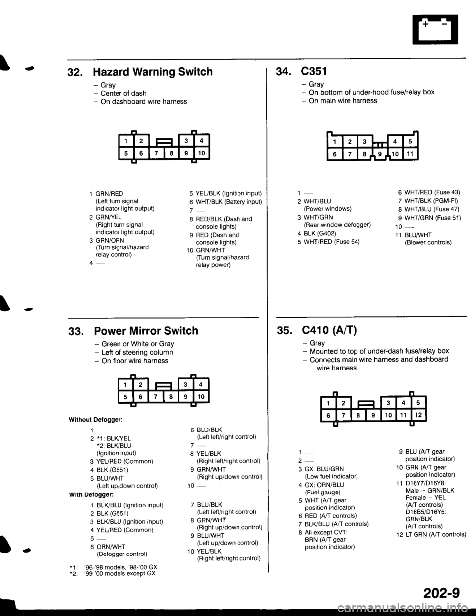
-32. Hazard Warning Switch
- Gray- Center ol dash- On dashboard wire harness
l GRN/RED(Left turn signalindicator light output)
2 GRN/YEL(Right turn signalindicator light output)
3 GRN/ORN
Ourn signal/hazardrelay control)
4
5 YEL/BLK (lgnition input)
6 WHT/BLK (Battery inpul)
7
8 RED/BLK (Dash andconsole lights)g RED (Dash andconsole lights)
1O GRNAVHT(Turn signal/hazardrelay power)
34. C351
- Gray- On bottom of under-hood fuse/relay box- On main wire harness
14
67I I9 I1011
2 WHT/BLU(Power windows)
3 WHT/GRN(Rear window defogger)
4 BLK (G402)
5 WHT/FED (Fuse 54)
6 WHT/RED (Fuse 43)
7 WHT/BLK (PGM-Fl)
8 WHT/BLU (Fuse 47)
I WHT/GRN (Fuse 51)
10 _
11 BLUAVHT(Blower controls)
33,
Without Oelogger:
1
2 *1: BLK,|YEL*2r BLKBLU(lgnition input)
3 YEURED (Common)
4 BLK (G551)
5 8LU,ryVHT(Left up/down control)
With Delogger:
1 BLIVBLU (lgnition input)
2 BLK (G551)
3 BLIVBLU (lgnition inPut)
4 YEURED (Common)
6 ORNMHT(Detogger control)
'96198 models, '98-'00 GX'99 00 models except GX
Power Mirror Switch
- Green or White or Gray- Left of steering column- On floor wire harness
6 BLU/BLK(Left left/right control)
8 YEUBLK(Right left/right control)
9 GRNAVHT(Right up/down control)
10
7 BLU/BLK(Lett left/right control)
8 GRNMHT(Right up/down control)
9 BLU/WHT(Lett up/down control)
1O YEL/BLK(Right left/right connol)
I
-
202-9
35. C41o (A/T)
- Gray- lilounted to top of underdash {use/relay box- Connects main wire harness and dashboard
wtre narness
2
3 GX: BLU/GRN
{Low fuel indicator)
4 GX: ORN/BLU(Fuelgauge)
5 WHT (A/T gearposition indicator)
6 RED (A,/T controls)
7 BLI(BLU (A,rT controls)
8 All except CVT:BRN (AiT gearposition indicator)
I BLU (Aft gearposition indicator)
10 GRN (A/I gearposition indicator)
11 D16Y7/D16Y8:Male - GRN/BLKFemale YEL(A/T conkols)D1685/D16Y5:GRN/BLK(M controls)
12 LT GRN (A/T controls)
Page 2117 of 2189
Connector Views (cont'd)
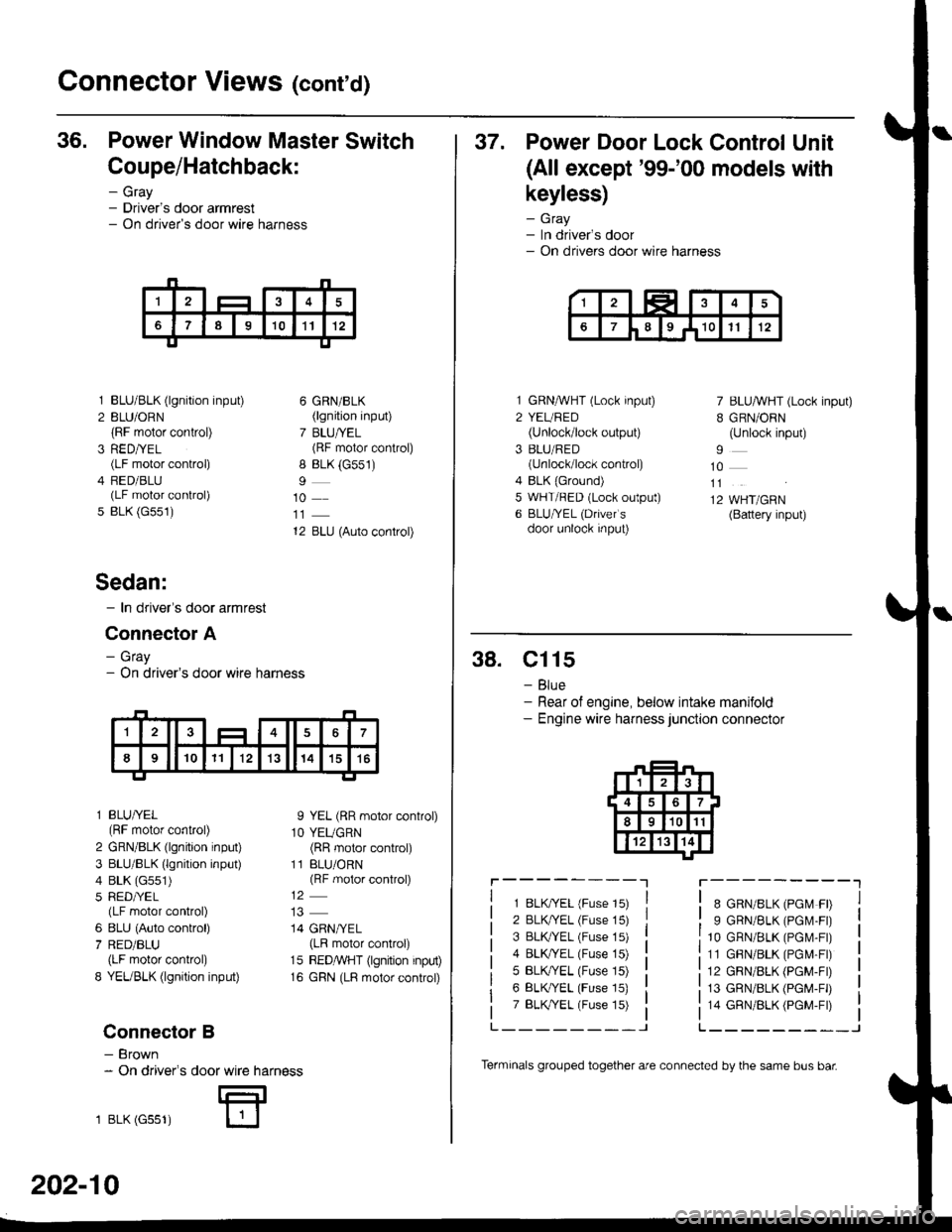
36. Power Window Master Switch
Coupe/Hatchback:
- Gray- Driver's door armrest- On driver's door wire harness
3
5
BLU/BLK (lgnition input)
BLU/ORN(RF motor control)
RED/YEL(LF motor control)
FED/BLU(LF motor control)
BLK (G551)
6 GRN/BLK(lgnition input)
7 BLU/YEL(RF motor control)
8 BLK (G551)
10
12 BLU (Auto control)
I YEL (RR motor control)
1O YEUGRN(RR motor control)
11 BLU/ORN(RF motor control)
14 GRN/YEL(LR motor control)
15 REDMHT (lgnition input)
16 GRN (LR motor control)
Sedan:
- In driver's door armrest
Connector A
- Gray- On driver's door wire harness
l BLU/YEL(RF motor control)
2 GRN/BLK (lgnition input)
3 BLU/BLK (lgnition input)
4 BLK (G551)
5 RED/YEL(LF motor control)
6 8LU (Auto control)
7 RED/BLU(LF motor control)
8 YEUBLK (lgnition input)
Connector B
- Brown- On driver's
1 BLK (Gss1)
door wire harness
E
202-10
Terminals grouped together are connected by the same bus bar
37. Power Door Lock Control Unit
(All except'99-'00 models with
keyless)
- Gray- In driver's door- On drivers door wire harness
1 GRNMHT (Lock input)
2 YEURED(Unlock/lock output)
3 BLU/RED(unlock/lock control)
4 BLK {Ground)5 WHT/RED (Lock output)
6 BLU/YEL (Drivefs
door unlock input)
7 BLU/WHT (Lock input)
B GRN/ORN(Unlock input)
10
11
12 WHT/GRN(Battery input)
38. Cl15
- Blue- Rear of engine, below intake manifold- Engine wire harness junction connector
r----------lr---------"1
1 8LK?ryEL (Fuse 15)
2 BLK/YEL (Fuse 15)
3 BLK TEL (Fuse 15)
4 BLK/YEL (Fuse 15)
5 BLK,/YEL (Fuse 15)
6 BLK/YEL (Fuse 15)
7 BLK,TYEL (Fuse 15)
8 GRN/8LK (PGM FD
9 GRN/BLK (PGM.FD
10 GRN/BLK (PGr\,4-Fr)
11 GBN/BLK (PGM-Fr)
12 GRN/BLK (PGM-FD
13 GRN/BLK (PGM-FD
14 GRN/BLK (PGM-Fr)
L_______-JL______--_J
Page 2119 of 2189
Connector Views (conrd)
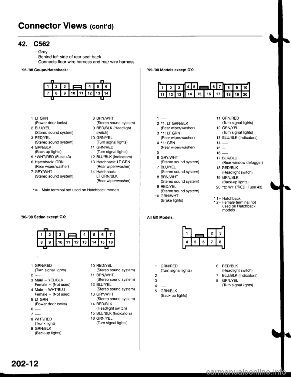
42. C562
- Gray- Behind left side ol rear seat back- Connects floor wire harness and rear wire harness
'96-'98 CouDe/Hatchbaqk:
* = Male terminal not used on Hatchback models
'96-'98 Sedan except GX:
1 LT GRN(Power door locks)
2 BLU/YEL(Stereo sound system)
3 RED/YEL(Stereo sound system)
4 GRN/BLK(Back-up lights)
5 *WHT/BED (Fuse 43)
6 Hatchback: GRN(Rear wiper/washer)
7 GRYAVHT(Stereo sound system)
l GRN/RED(Turn signal lights)
2_
3 l,4ale - YEUBLKFemale - (Not used)
4 ftrale - WHT/BLUFemale - {Not used)
5 LT GRN(Power door locks)
8 WHT/RED(Trunk light)
9 GRN/BLK(Back-up lights)
8 BRNMHT(Stereo sound system)
9 RED/BLK (Headlight
switch)
1O GFN/YEL(Turn signal lights)
l1GRN/RED
Ourn signal lights)
12 BLU/BLK (lndicators)
13 Hatchback: LT GBN(Rear wiper/washer)
14 Hatchback:LT GRN/BLK(Rear wiper/washer)
1O RED/YEL(Stereo sound system)
11 BRNA,ryHT(Stereo sound system)
12 BLU/YEL
{Stereo sound system)
13 GRYA/VHT
{Stereo sound system)
14 RED/8LK(Headlight switch)
15 BLU/BLK (lndicators)
16 GRN/TEL(Turn signallights)
202-12
'99-'00 Models exceDl GX:
1
2 11: LT GRN/BLK(Rear wiper/washe0
3 *1: LT GRN(Rear wiper/washe0
4 a1r cRN(Rear wiper/washe0
6 GRYMHT(Stereo sound system)
7 BLU/YEL(Stereo sound system)
8 BRN,^/VHT(Stereo sound system)
9 REDA/EL(Stereo sound systern)
10 GRN,^/VHT(Brake lights)
All GX Models:
GRN/RED(Turn signal lights)
GBN/BLK(Back-up lights)
11 GRN/RED(Turn signal lights)
12 GRN/YEL
Ourn signal lights)
13 BLU/BLK (lndicators)
14
16
17 BLI(BLU(Reaf window defogger)
18 RED/BLK(Headlight switch)
19 GRN/BLK(Back-up lights)
20 *2: WHT/FED (Fuse 43)
* 1 = Hatchback* 2= Female terminal notused on Hatchbackmooers
RED/BLK(Headlight switch)
BLU/BLK (lndicators)
GRN/YEL(Turn signal lights)
6
7
I
2
3
4
5
'I24t56I7I910
't11214151617't81920