Page 2123 of 2189

Connector Views (cont'd)
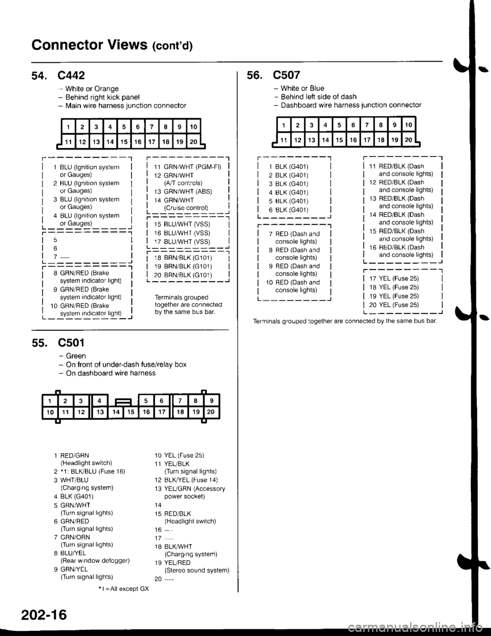
54. c442
- White or Orange- Behind right kick panel- l\,lain wire harness junction connector
r---------Tr---------"1
1 BLU (lgnition systemor Gauges)
2 BLU (lgnition syslemor Gauges)
3 BLU (lgnition systemor Gauges)
4 BLU (lgnition system
L_ or causes)L_-:-:::'-'�____Jt-----------1
11 GRN/WHT (PGM-FD
12 GRN/WHT(A/T controls)
13 GRNMHT (ABS)
14 GRNMHT
L_ lc,r'." .oIr"D_ _ _.jr----------_l
5
6
7L---------JT----------l8 GRN/RED (Brake
system indicator light)
9 GRN/RED (Brake
system indicator light)
10 GRN/RED (Brake
_ system indicator ligh0 -..1
| 15 BLUMHT (vSS) |I 16 BLUMHT (VSS) I
L T?_BLUSTrySS)--..]
l--------- - -l
| 18 BFN/BLK (G101) I| 19 BBN/BLK (G101) || 20 BRN/BLK (c101) |L---------J
Terminals groupedtogether are connectedby the same bus bar.
55. C501
- Green- On tront of under-dash tuse/relay box- On dashboard wire harness
l RED/GFN(Headlight switch)
2 *1 : BLKBLU (Fuse 16)
3 WHT/BLU(Charging systern)
4 BLK (G401)
5 GRNMHT(Turn signal lights)
6 GRN/RED(Turn signal lights)
7 GRN/ORN(Turn signal lights)
8 8LU/YEL(Rear w ndow delogger)
9 GFN/YEL(Turn signal lights)
'10 YEL (Fuse 25)
11 YEL/BLK(Turn signal lights)
12 BLKTYEL (Fuse 14)
13 YEUGRN (Accessorypower socket)
15 RED/BLK(Headlight switch)
1B BLK/WHT(Charglng system)
19 YEL/RED(Stereo sound system)
20
202-16
-1 =All e),cept GX
s6. c507
- White or Blue- Behind left side oJ dash- Dashboard wire harness junction connector
r --------'lT---------l
7 BED (Dash andconsole lights)
B BED (Dash andconsole lights)
I RED (Dash andconsole lights)
10 RFD (Dash andconsole lights)
11 RED/BLK (Dash
and console lights)
12 RED/8LK (Dash
and console lights)
13 RED/BLK {Dashand console lights)
14 RED/BLK (Dash
and console lights)
15 RED/BLK (Dash
and console lights)
16 RED/BLK (Dash
and console lights)L--------J
T--------T
L---_---_J
1 BLK (G401)
2 BLK (G401)
3 8LK {G401)4 8LK (G401)
5 BLK (G401)
6 8LK (G401)L________J
T--------"1
17 YEL (Fuse 25)
18 YEL (Fuse 25)
19 YEL (Fuse 25)
20 YEL (Fuse 25)L--------J
Term nals grouped together are connected by the same bus bat
Page 2133 of 2189

Connector Views (cont'd)
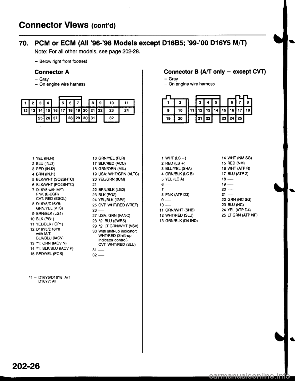
70. PCM or ECM (All '96-'98 Models except D1685; '99-'00 D16Y5 MfO
Note: For all other models, see page 202-28.
- Below right tront footrest
Connector A
- Gray- On engine wire harness
12346I91011
12131415't617'182021222324
25262?2829303'r32
1 YEL (rNJ4)
2 BLU (rNJ3)
3 RED (rNJ2)
4 BRN (NJ1)
5 BLI(WHT (SO2SHTC)
6 BL(WHT (PO2SHTC)
7 D16Ys with M/TlPNK (E-EGR)
CWi RED (ESOL)
8 D16Y5/016Y8:GRN/rEL (wS)
9 BRNiBLK (LG1)
10 BLK (PGl)
11 YEUBLK (lGPl)
12 D16Y5/016Y8
BLI(BLU 0ACV)13 11: ORN {IACV N)
14 11r BLKBLU (IACV P)
15 RED/yEL (PCS)
16 GRNffEL (FLB)
17 BLI(FED (ACC)
18 GRN/ORN (MrL)
19 USA: WHT/GRN (ALTC)
20 YEUGnN (CM)
22 BRN/BLK (LG2)
23 BLK (PG2)
24 YEUBLK (tGP2)
2s CW: WHT/REO (VBEF)
27 USA| GRN (FANC)
28 .2r BLU (2WBS)
29 .2r LT GRNAVHT (VSV)
30 with shift-up indicator:WHT/RED (Shift-upindjcator control)CW; WHTiRED (SLU)
*1 = D16Y5/D16Y8: A"/TD16Y7: All
202-26
Connector B (A/T only - except CW)
- Gray- On engine wire harness
I wHT (LS -)
2 RED (LS +)
3 BLU/YEL (SHA)
4 GRNi BLK (LC B)
s YEL (LC A)
8 PNK (ATP D3)
9_
10 _
11 GRN,4 HT (SHB)
12 WHT/RED (SLU)
13 GRN/BLK (D4 rND)
14 WHT (NM SG)
1s RED (NM)
16 WHT (ATP R)
17 BLU (ATP 2)
18 -
19 -
22 GRN (NC SG)
23 BLU (NC)
24 YEL (ATP D4)
25 LT GRN (ATP NP)
Page 2135 of 2189

Connector Views (conrd)
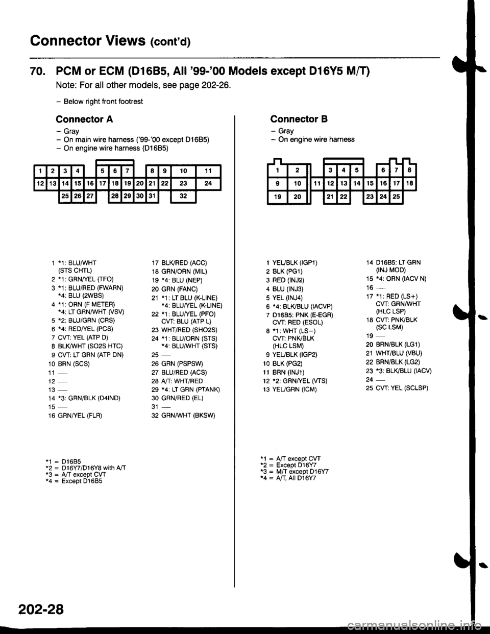
70. PCM or ECM (D1685, All '99-'00 Models except Dl6Y5 Mff)
Note: For all other models, see page 202-26.
- Below right tront footrest
Connector A
- Gray- On main wire harness ('99100 except 01685)- On engine wire harness (D1685)
246789t011
't21314t516'17'18192021222324
2526272a29303132
1 *1: BLUAVHT(srs cHrL)
2 *1: GRNffEL [rFO)3 -1I BLU/RED (FWARN)14: BLU {2WBS)4 *1:ORN (F METER).ar LT GRN/WHT (VSV)
5 *2: BLU/GFN (CRS)
6 .4r RED/YEL (PCS)
7 CVT: YEL iATP D)
I BLI(WHT (SO2S HTC)
9 CW: LT GRN (ATP DN)
10 BRN (SCS)
14 13: GRN/BLK (D4|ND)
16 GRN/yEL (FLR)
'1 = D16B5"2 = D 16Y7/D 1 6Y8 with A"/Ta3 = A,/T except CW*4 = Except D1685
17 BU(RED (ACC)
18 GRN/ORN (Mrr)
19 .4: BLU (NEP)
20 GRN (FANC)
21 *1: LT BLU (K-LINE).4: BLU/YEL (K-LINE)
22 *1: BLU/YEL (PFO)CVT: ALU (ATP L)
23 WHT/RED (SHO2S)
24 *1 : BLU/ORN (STS)*4: BLU/^,iVHT (STS)
26 GRN (PSPSW)
27 BLU/BED (ACS)
28 A"/T: WHT/RED
29 *4: LT GRN (PTANK)
30 GRNiRED (EL)
32 GRNAVHT (BKSW)
202-28
Connector B
- Gray- On engine wire harness
I YEUBLK (IGP1)
2 BLK (PG1)
3 RED (rNJ2)
4 BLU (rNJ3)
5 YEL (NJ4)
6 i4: BL(BLU (IACVP)
7 D1685: PNK (E-EGR)
CW: RED (ESOL)
8 'l: WHT (LS-)
CVT: PNIVBLK(HLC LSI\,!)
9 YEUBLK (IGP2)
1o BLK (PG2)
11 BRN (NJ1)
12 '2: GRN/YEL (VTS)
13 YEUGRN (CM)
14 01685: LT GRN(NJ MOD)
15 .4r ORN (IACV N)
16 _
17 .1r RED (LS+)
CW: GRN/WHT(HLC LSP)
18 CW: PNKBLK(sc LsM)
19
20 BRN/BLK (LGl)
21 WHT/BLU (VBU)
22 BRN/BLK (LG2)
23 r3: BL(BLU (IACV)
25 CW: YEL (SCLSP)
a1 = A"fT except CVTa2 = Except 016Y7'3 = M,/T except D16Y714 = A/T, All D16Y7
Page 2168 of 2189

)\
) -,
.'
'1: With shift-up indicator or cruise control system ('96-'97 models)
With cruise control system ('98-'00 models)
.2: '96198 models.3: '99-'00 models
c5o9 csrr c510 c515
13 1c517
DISHAOABD w|REIIARNESS
Connector
or
Terminal
Number of
Cavities/
Color
LocationConnects toNotes
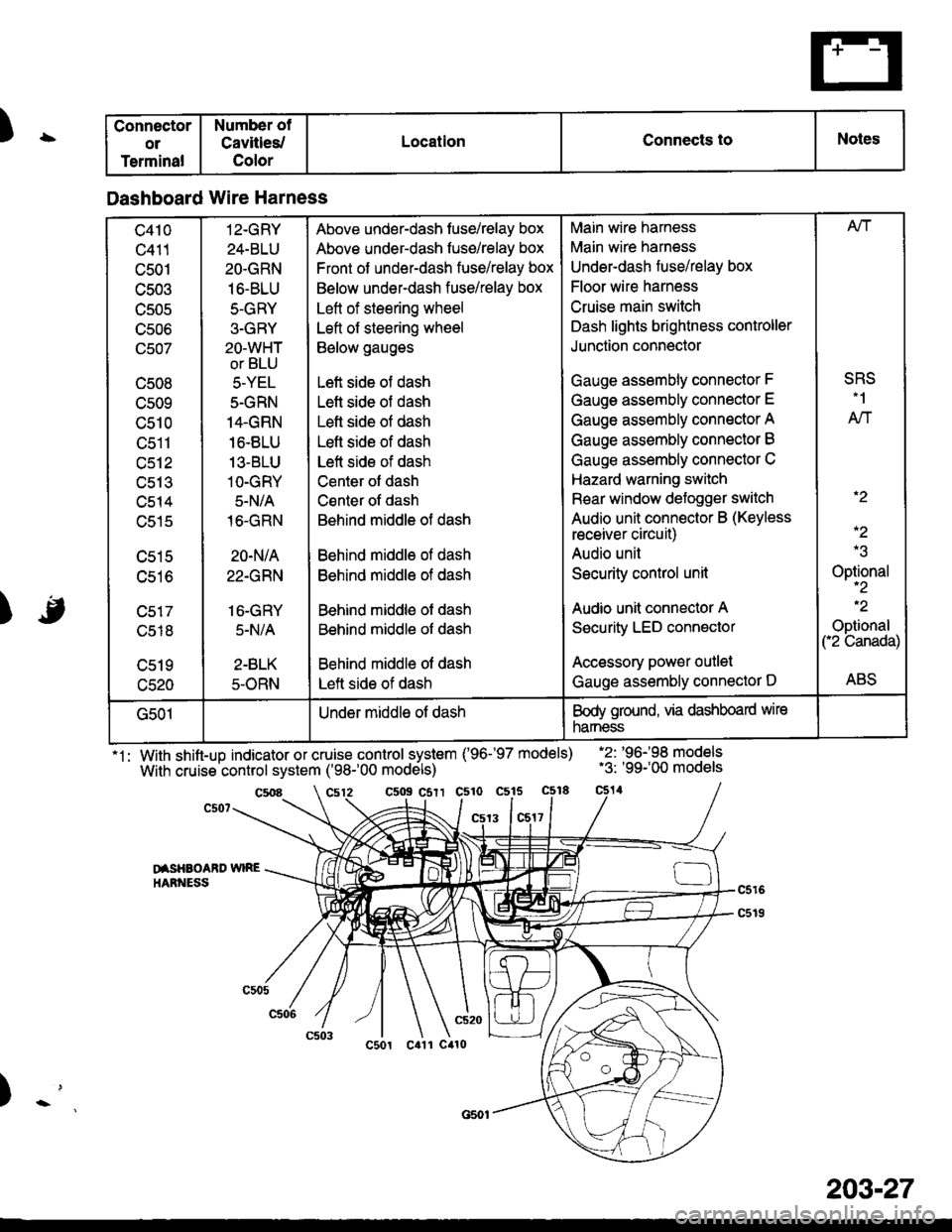
Dashboard Wire Harness
c410
c411
c501
c503
TJJUC
UCUO
(Jcu/
c508
cs09
c510
tJctl
c512
uc t.t
c514
c515
c516
c518
c520
12-GRY
24-BLU
2O.GRN
16-BLU
5-GRY
3-GRY
2O-WHT
or BLU
5-YEL
5-GRN
14.GRN
16.8LU
13-BLU
1O-GRY
5-N/A
16-GRN
20-N/A
22.GRN
16-GRY
5.N/A
2-BLK
5-ORN
Above under-dash fuse/relay box
Above under-dash fuse/relay box
Front of under-dash fuse/relay box
Below under-dash fuse/relay box
Left of steering wheel
Left of steering wheel
Below gauges
Left side of dash
Lett side of dash
Left side of dash
Lefl side of dash
Left side of dash
Center ot dash
Csnter of dash
Behind middle of dash
Behind middle ol dash
Behind middle of dash
Behind middle of dash
Behind middle of dash
Behind middle of dash
Left side of dash
Main wire harness
Main wire harness
Underdash fuse/relay box
Floor wire harness
Cruise main switch
Dash lights brightness controller
Junction connector
Gauge assembly connector F
Gauge assembly connector E
Gauge assembly connector A
Gauge assembly connector B
Gauge assembly connector C
Hazard warning switch
Rear window defogger switch
Audio unit connector B (Keyless
receiver circuit)
Audio unil
Security control unit
Audio unit connector A
Security LED connector
Accessory power outlet
Gauge assembly connector D
Afi
SRS.1
AN
.2
-2
Optional-2
.2
Optional("2 Canada)
ABS
G501Under middle of dashBody ground, via dashboard wire
narness
203-27