1996 HONDA CIVIC washer pump
[x] Cancel search: washer pumpPage 58 of 2189
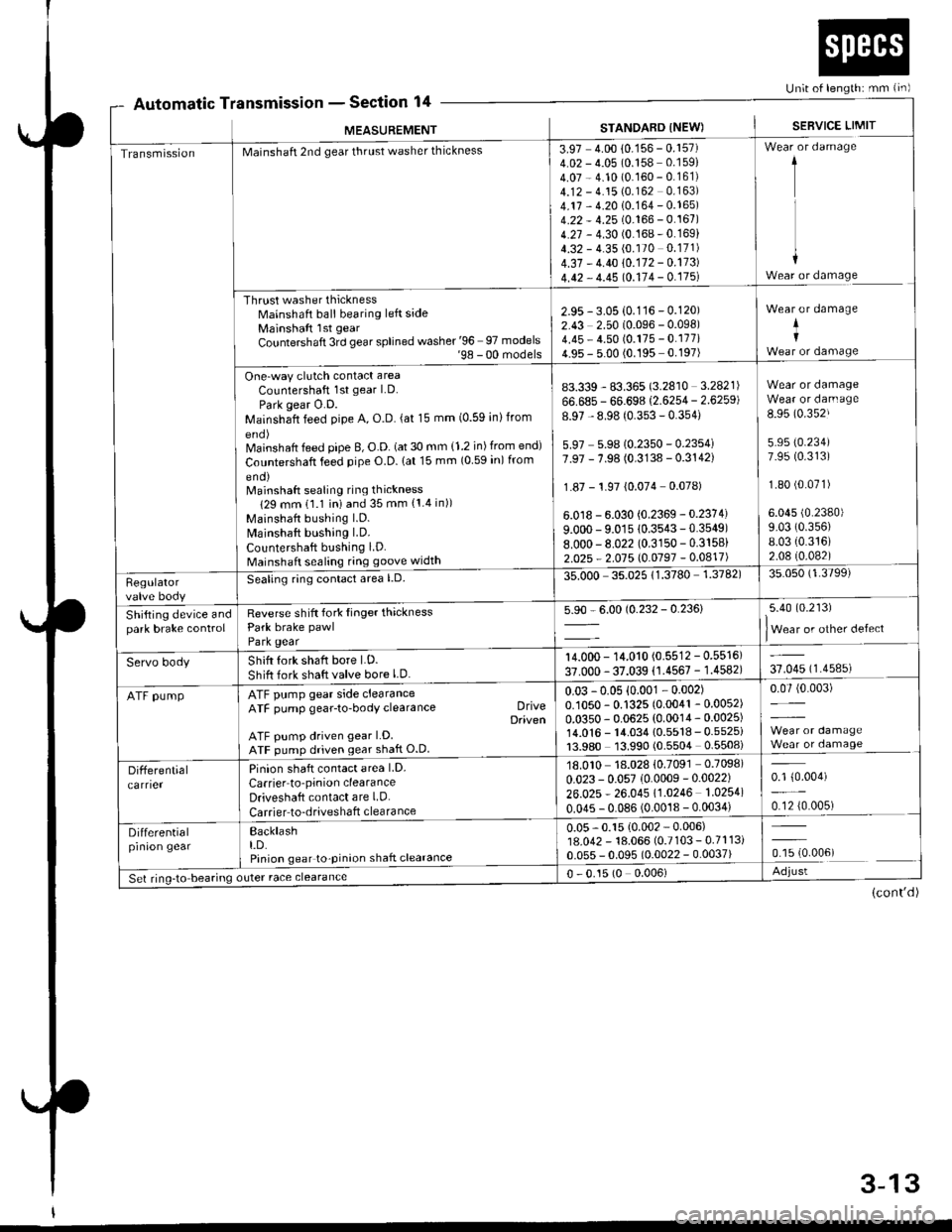
Automatic TnsmtsstonSection 14Un;t of length: mm {in)
r
MEASUREMENT
a
STANDARD INEW)SEBVICE LIMIT
TransmissionMainshaft 2nd gear thrust washer thickness
Thrust washer thicknessMainshaft ball bearing left sideMainshaft lst gear
Countershaft 3rd gear splined washer '96 97 models'98 - 00 models
One-way clutch contact area
Countershaft 1st gear LD.
Park gear O.D.Mainshaft feed pipe A, O.D. (at 15 mm (0.59 inlfrom
Mainshaft feed pipe B, O.D. (at 30 mm {1.2 in) from end)
Countershaft feed pipe O.D. lat 15 mm (0 59 in) from
eno)Mainshaft sealing ring thickness
129 mm 11.1 iniand 35 mm {1.4 in))
Mainshaft bushing l.D.
Mainshaft bushing LD.
Countershaft bushing LD.Mainshaft sealing ring goove width
3.97 4.00 10.156 - 0.157)4.02 - 4.05 (0.158 0.159)
4.07 - 4.10 (0.160 - 0.161)4.12 - 4.15 (0.162 0.163)
4.17 - 4.20 10.164 - 0.165)4.22 - 4.25 (0.166 - 0.167)4.27 - 4.30 (0.168-0.169)
4.32 - 4.35 (0.170 0.171)
4.37 - 4.40 10.172 - 0.173)
4.42 - 4.45 10.114 - 0.175l
1
I
+Wear or damage
2.95 - 3.05 {0.116 - 0.120)2.43 2.50 (0.096 - 0.098)4.45 - 4.50 (0.175 - 0.177i4.95 - 5.00 (0.195 0.197)
Wear or damage
+I
83.339 - 83.365 (3.2810 3.2821)
66.685 - 66.698 (2.6254 - 2.6259)
8.97 - 8.98 (0.353 - 0.354)
5.97 5.9810.2350 - 0.2354i7.97 - 7.98 (0.3138 - 0.3142)
1.87 - 1.97 {0.074 0.078)
6.0 r8 - 6.030 {0.2369 - 0.2374)
9.000 - 9.01s 10.3543-0.3549)8.000-8.022 (0.3150 - 0.3158)
2.025 - 2.015 l0.0197 -0.0417)
Wear or damageWear or darn age
8.95 (0.352J
5.95 (0.234)
7.95 (0.313)
1.80 (0.071)
6.045 (0.2380)
9.03 (0.356)
8.03 {0.316)2.08 (0.082)
Regulatorvalve body
Seating ring conlact area l.D.35.000 35.02511.3780 1.3782)35.050 (1.3799)
Shifting device andpark brake controlReverse shift fork Iinger thicknessPark brake pawl
Park gear
5.90 - 6.00 (0.232 - 0.236)5.40 (0.213)
lWear or other defect
Servo bodyShift fork shaft bore LD.
Shift fork shaft valve bore l.D.
14.000 - 14.010 (0.5512 - 0.5516)
37.000 - 37.039 (1.4567 - 1.4582)37.045 (1.4585)
ATF pumpATF pump gear side clearanceATF pump gear-to-body clearance DriveDaiven
ATF pump driven gear LD.ATF pump driven gear shaft O.D
0.03 -0.05 {0.001 - 0.002)0.1050 - 0.1325 (0.0041 - 0.0052)
0.0350 - 0.0625 (0.0014 - 0.0025)14.0'�|6 - 14.034 {0.5518 - 0.5525i13.980 13.990 (0.5504 0.5508)
0.07 (0.003)
Differentialcarrier
Pinion shaft contact area LD.
Carrier to'pinion clearanceDriveshaft contact are LD.
Carrier to-driveshaft clearance
18.010 18.028 {0.7091 0.7098)
0.023 - 0.057 (0.0009 -0.0022)
26.025 * 26.045 11.0246 1.0254)
0.045 - 0.086 (0.0018 - 0.0034)
0.1 {0.004)
0.12 {0.005)
Differentialprnron gearBacklasht.D.Pinion gear to-pinion shaft clearance
0.05 - 0.15 {0.002 - 0.006)18.042 - 18.066 (0.7103 - 0.7113i0.055 - 0.095 (0.0022 - 0.0037)ffi.oour
Set ring-to bearing outer race clearance0 - 0.15 (0 0.006)Adjust
(cont'd)
3-13
Page 178 of 2189
Cylinder Head
Removal (cont'd)
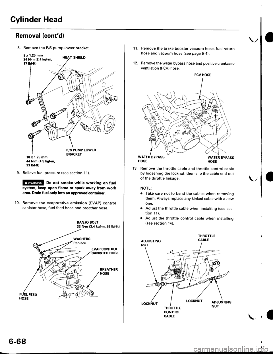
8. Remove the P/S pump lower bracket.
8 x 1.25 mm24 N.m 12.4 kgf.m,17 tbtftl
9.
T SHIELD
10.
P/S PUMP LOWERBRACKET10 x 1.25 mm44 N.m {4.5 kgf.m,33 tbf.frl
Relieve fuel pressure (see section l1).
@ Do not smok6 while working on fuel
system, keep open flam€ or spark away lrom work
ar€a, Drain fuelonly into an approved cortain€r.
Remove the evaporative emission (EVAP) control
canister hose, fuel feed hose and breather hose.
BANJO BOLT33 N.m (3.4 kgl.m.25 lbf.ftl
BREATHERHOSE
WASHERS
6-68
\.
11. Remove the brake booster vacuum hose, fuel return
hose and vacuum hose (see page 5 4).
12. Remove the water bypass hose and positive crankcase
ventilation (PCV) hose.
WATER BYPASSHOSEWATER EYPASSHOSE
Remove the throttle cable and throttle control cable
by loosening the locknut, then slip the cable end out
of the throftle linkage.
NOTE;
. Take care not to bend the cables when removing
them. Always replace any kinked cable with a new
one.
. Adjust the throttle cable when installing (see sec-
tion I I ),. Adjust the throttle control cable when installing(see section 14).
CONTROLCABLE
1a
PCV HOSE
Page 200 of 2189
lllustrated Index
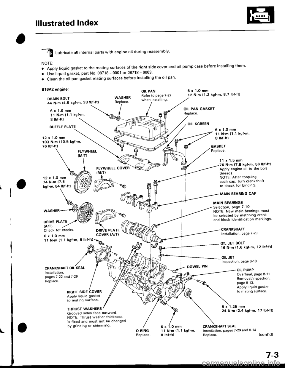
I runricate att internal parts with engine oil during reassembly'
NOTE:
o Apply liquid gaskettothe mating surfaces ofthe right side cover and oil pumpcase before installingthem'
. Use liquid gasket, part No 08718-0001 or08718-0003'
. Clean the oil pan gasket mating surfaces betore installing the oil pan
81642 engine:
DRAIN BOLT44 N,m {4.5 kgf'm,33 lbt'ft)
6 x 1.0 mm'11 N.m (1.1 kgI'm,
I tbl.ft)
OIL PANReter to page 7 27when installing.
6 r 1.O mm12 N.m t1.2 kgl'm, 8 7 lbf'lt)
OIL PAN GASKET
BUFFLE PLA
12 x 1.0 mm103 N.m {10.5 kgf'm,
76 tbr.ft)
6 x 1.0 mm11 N.m (1 .1 kgf.m,
8 tbI.fr)
GASKETReplace.FLYWHEEL(M/TI
12 x 1.0 mm
74 N.m (7.5
kof.m, 54 lbf'ft)
1^c{Eb\%^ t*^
*o"rr^--(Wffi
oa*,trto2,.w
FLYWHEEL COVER
IM/T)
DRIVE PLATECOVER (AiT)
11 x 1.5 mm76 N.m (7.9 kgf'm, 56 lbf'ft)
Apply engine oil to the bolt
threads.NOTE: After torqurngeach cap, turn crankshaft
to check for binding.
MAIN EEARING CAP
MAIN BEARINGSSelection, page 7_10
NOTE: New main bearings musl
be selected bY matching crank
and block identification markrngs
CRANKSHAFTInstallation, Page 7'23
OIL JET BOLT16 N.m 11.6 kgf'm, 12 lbl'ft)
OIL JETInspection, Page 8_10
Check for cracks
6x1.0mm11 N.m {1.1 kgf'm, I lbf'ft}
CRANKSHAFT OIL SEAL
Installation,pagesl 22 andl 29
Replace-
DOWEL PINOIL PUMPOverhaul, page 8-'l1Removal/lnspection,page 8-13.Apply liquid gasket
to mating surlace.RIGHT SIDE COVERApply liquid gasket
to mating surface.
THRUST WASHERS8 x 1.25 mm24 N.m {2.4 kgf.m, 17 lbf'ft)Grooved sides face outward
NOTE: Thrusr washer thickness
is tixed and must not be changed
by grinding or shimming
O-RINGReplace
CRANKSHAFT SEAL11 N.m {1.1 kgf'm, lnstallation, pages 7'29 and I 14
a lbt.ltl Heplace. (cont'd)
d#*
Page 201 of 2189

lllustrated Index
(cont'dl
I Luoricate att internal parts with engine oil during reassembly.
NOTE:
' Apply liquid gasket to the mating surfaces ofthe rightside coverand oil pumpcase before installingthem.. Use liquid gasket, part No. 08718 - 0001 or 087,18 _ OOO3.. Clean the oil pan gasket mating surfaces before installing it.
D16Y7 engine:6 x 1.0 mm12 N.m (1.2 kgt.m.8.7 tbf.tr)DRAIN BOLT44 N.m {4.5 kgt.m.33 tbt.ttl
,(
I
I
OIL PAN GASKETFLYWHEEL COVERIM/T)6x 1.0 mm12 N.m ('l .2 kgt.m, 8.7 tbt.trl
OIL PANRefer to page 7-27
Apply liquid gasker tothese points.
Replace.
WASHERReplace.12 x '1.0 mm118 N.m{12.0 kgt.m, 87 tbf.tr}
11 x 1.5 mm51 N.m15.2 kgl.m,38lbtftl
Apply engine oilto the boltthreads.NOTE: After torquingeach cap, turn the crankshaftto check for binding.
MAIN BEARINGSSelection, page 7-10
MAIN BEARING CAP
CRANKSHAFTInstallation, page 7 23
NOTE: New main bearings mustbe selected by matching crankand block identification markings.
6 r 1.0 mm11 N.m {1.1
6 x 1.0 mm11 N.m 11.1
ksI.m, 8 lbt.ft)
OIL SCREEN
kgt.m, 8 lbf.trl
Check for cracks.
CRANKSHAFT OIL SEALInstallation,pages 1 22 a^d 7-29
\:eprace'
GASKETReplace.
6 x 1.O mm11 N.m {1.1 kgt.m,8 rbt.frl
RIGHT SIDE COVERApply liquid gasker1o matrng surface,
OIL PUMPOverhaul, page 8-12Bemoval/lnspection,page 8-13
DOWEL PIN
WASHERSGrooved sides face outward.NOTE: Thrust washer thicknessis fixed and must not be changedby grinding or shimming.
CRANKSHAFT SEAL
l.j"Ji:l"^ pages z.2e --.S)
Replace.
6 x 1.0 mm11 N.m {1.18 tbt.fr)
7-4
BREATHING PORT COVERMOUNT BOLTS6 x 1.0 mm11 N.m {1.1 kgt.m, 8 tbf.fr}Apply liquid gasker tothe boh threads.
DOWEL PIN
Page 202 of 2189

D16Y5, D16Y8 engines:
DRAIN BOLT39 N.m 14.0 kgt'm,
Apply liquid gasket to
these points.
OIL PANRefer to page 7-25
when installing.WASHERReplace.
29 lbl.tt)
\
\^
6 x 1.0 mm q%
P
I
FLYWHEEL COVER(M/T}
12 x 1.0 mm118 N.m(12.0 kgt.m, 87 lbt'ft)
FLYWHEEL (M/TI
t2 N.m 11.2 kgf'm,
8.7 lbl.ftl
11 x 1.5 mm
51 N.m(5.2 kgf'm, 38 lbf ftl
Apply engine oiltothe bolt
threads.NOTE: Aftertorquingeach cap, turn crankshaft
to check for binding.
MAINBEARING
MAIN BEARINGSSelection, page 7-10NOTE: New main bearings must
be selected by matching crank
"nJ lr."i io"irriti"",ion-markings. --------*-i6{\
CRANKSHAFTInstallation, page 7-23
6 r 1.0 mm11 N.m (1 1 kgf'm, I lbf'ttl
OII PAN GASKETReplace.
DRIVE PLATE COVER
{A/T or CVT)
12 r 1.0 mm
74 N.m
17.5 kgl.m, 54 lbf'ft)
DBIVE PLATE {A/T or CVTI
Check for cracks
6 x 1.O mm11 N.m {1.1 kgl'm,
8 tbl.ftl
CRANKSHAFT OIL SEAL
lnstallation,pages 7'?1 and '1 '28
Replace.
RIGHT SIDE COVER
Apply liquid gasket
to mating surface.
OIL SCREEN
GASKETReplace.
OIL PUMPOverhaul, page 8_12Removal/lnspection,page 8-13Apply liquid gasket
to mating surface.
DOWEL PIN
WASHEFS
Grooved sides tace outward
NOTE: Thrust washer thickness
is fixed and must not be changed
bV grinding or shimming.
CRANKSHAFT SEALInstallation, pages 7 29
and 8-14Replace.
BREATHING PORT COVER
MOUNT BOLTS6 x 1.O mm11 f{..n (1.1 kgf'm, 8 lbf'fl)
Apply liquid gasket to
the bolt threads.
O.RINGReplace.
6 x 1.0 mm
11 N.m (1 1 kgl'm,
8 tbr.ftl
(cont'd)
7-5
\
OOWEL PIN
Page 499 of 2189
Fuel Supply System
System Description
The fuel supply system consists of a fuel tank, in-tank
high pressure fuel pump, PGM-FI main relay, fuelfilter,
fuel pressure regulator, fuel injectors. and fuel delivery
and return lines. This system delivers pressure-regu-
lated fuel to the fuel injectors and cuts the fuel delivery
when the engine is not running.
Fuel Pressure l'96 Modelsl
Relieving
Before disconnecting fuel pipes or hoses, release pres-
sure from the system by loosening the 6 mm service
bolt on top of the fuel filter.
. Do not smoke whil6 working on the fuel system.
Kgsp opon flames or sparks away from youl work
area.
. Be sure to relieve fuel pressure while the ignition
switch is off.
1. Write down the frequencies for the radio's preset
buttons.
2. Disconnect the battery negative cable from the bat-
tery negative terminal.
3. Remove the fuelfill cap,
4. Use a box end wrench on the 6 mm service bolt at
the fuel filter while holding the special banjo bolt
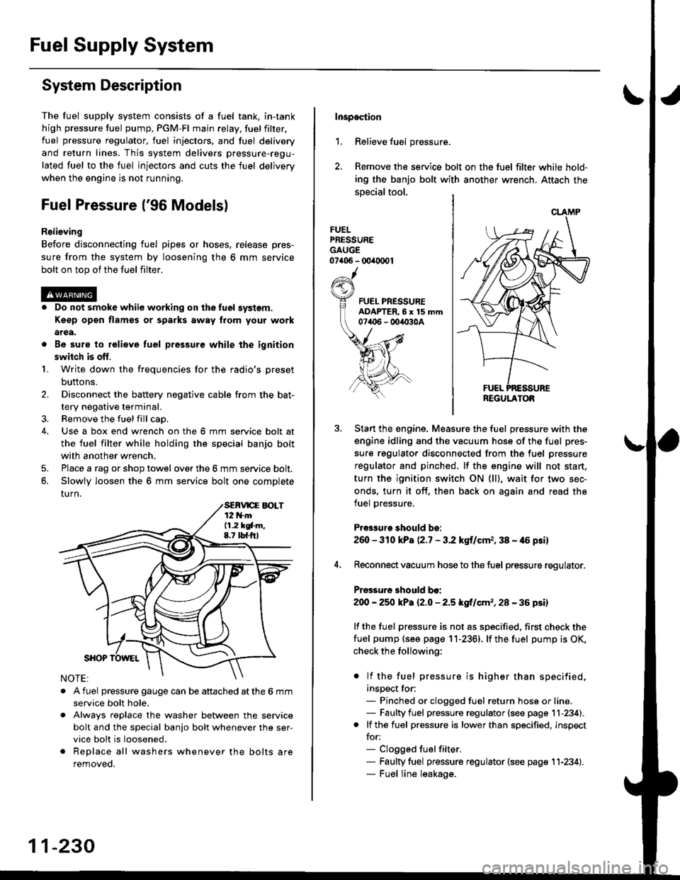
with another wrench,
5. Place a rag or shop towel over the 6 mm service bolt.
6, Slowly loosen the 6 mm service bolt one complete
rurn.
. A fuel pressure gauge can be attached at the 6 mm
service bolt hole.
. Always reDlace the washer between the service
bolt and the special banjo bolt whenever the ser-
vice bolt is loosened.
. Replace all washers whenever the bolts are
removeo.
11-230
Inspoction
1. Relieve fuel pressure.
2. Remove the service bolt on the fuel filter while hold-
ing the banjo bolt with another wrench. Attach the
special tool.
FUELPRESSUREGAUGE07406 - 00ir0(x)1
Start the engine. Measure the fuel pressure with the
engine idling and the vacuum hose of the fuel pres-
sure regulator disconnected from the fuel pressure
regulator and pinched. lf the engine will not start,
turn the ignition switch ON (ll), wait for two sec-
onds, turn it off, then back on again and read the
fuel pressure.
Pr€3sure should bo:
260 - 310 kPa (2.7 - 3.2 kgt/cmr, 38 - 46 psi)
Reconnect vacuum hose to the fuel pressure regulator,
Pressure should bo:
200 - 25O kPa l2.O - 2.5 kgf/cm'�, 28 - 36 psil
lf the fuel pressure is not as specified, first check the
fuel pump {see page 11-2361. lf the fuel pump is OK,
check the following:
. lf the fuel pressure is higher than specified,
inspect for;- Pinched or clogged fuel return hose or line.- Faulty fuel pressure regulator (see page 11-234).. lf the fuel pressure is lower than specified, inspect
for:- Clogged fuelfilter.- Faulty fuel pressure regulator {see page 11-234).- Fuel line leakage.
REGULATOB
Page 500 of 2189

tJFuel Pressure {'97 and later Models)
ReliGving
Before disconnecting tuel pipes or hoses, release pres-
sure from the system by loosening the 12 mm banjo
bolt on top of the fuel filter.
@o Do not smoke whilo working on the fuel sy3lom.
Ksgp op€n flames or sparks away tlom Your work
arga.
. Be sure to relieve fuel pressule while the ignition
swhch is off.
1. Write down the frequencies for the radio's preset
buttons,
2. Disconnect the battery negative cable from the bat-
tery negative terminal.
3. Remove the fuel fill cap.
Use a box end wrench on the 12 mm banjo bolt at
the fuel filter while holding the fuel filter with anoth-
er wrench.
Place a rag or shop towel over the 12 mm banio bolt.
Slowly loosen the 12 mm banjo bolt one complete
turn.
4.
I
12 mm BAtt OBOLT33 N.m (3.i1 kgf m,25 tbf.f0
NOTE: Replace all the washers whenever the 12
mm banio bolt is loosened or removed.
Inspaqtion
1. Relieve fuel pressure.
2. Remove the 12 mm banjo bolt from the fuel filter
while holding the fuel Jilter with another wrench
Attach the special tools.
3. Start the enginethe fuel Pressure with the
engine idling and the vacuum hose of the fuel pres-
sure regulator disconnected from the fuel pressure
regulator and pinched lfthe engine will not start, turn
the ignition switch ON {ll), wait for two seconds, turn
it off, then back on again and read the fuel pressure'
Pr$3uro ehould be:
excepi 816A2 sngine:
260 - 310 kPa {2'7 - 3.2 kgf/cm" 38 - {6 Fi}
B16A2 engine:
27O -32O kPa P.8 - 3'3 kgf/cm'�, '10 - 47 psi)
4. Reconnect vacuum hoso to the fuel pressure regulator'
Pre33ure 3hould be:
except B16A2 engin€:
2OO - 250 kPa {2.0 - 2'5 kgf/cm'�, 28 - 36 psi)
B16A2 engino:
210 - 260 kPa 121 - 2.6 ksf/cm'�, 30 - 37 psi)
lf the fuel pressure is not as specified, first check the
fuel pump (see page 11-236) lfthetuel pumpisoK,
check tho following:
. lf the fuel pressure is higher than specified,
inspect for:- Pinched or clogged fuel return hose or line.
- Faulty fuel pressure regulator (see page 11-
2341.
. lf the fuel pressure is lower than specified, inspect
for:- Clogged fuel filter.
- Faulty fuel pressure regulator (see page l1-
2341.- Fuel line leakage.
FUEL PRESSUREADAPTER BOLT, 12 mm
tguxt8-PD6-0101
CLAMP
REGULATOR
11-231
Page 504 of 2189
I
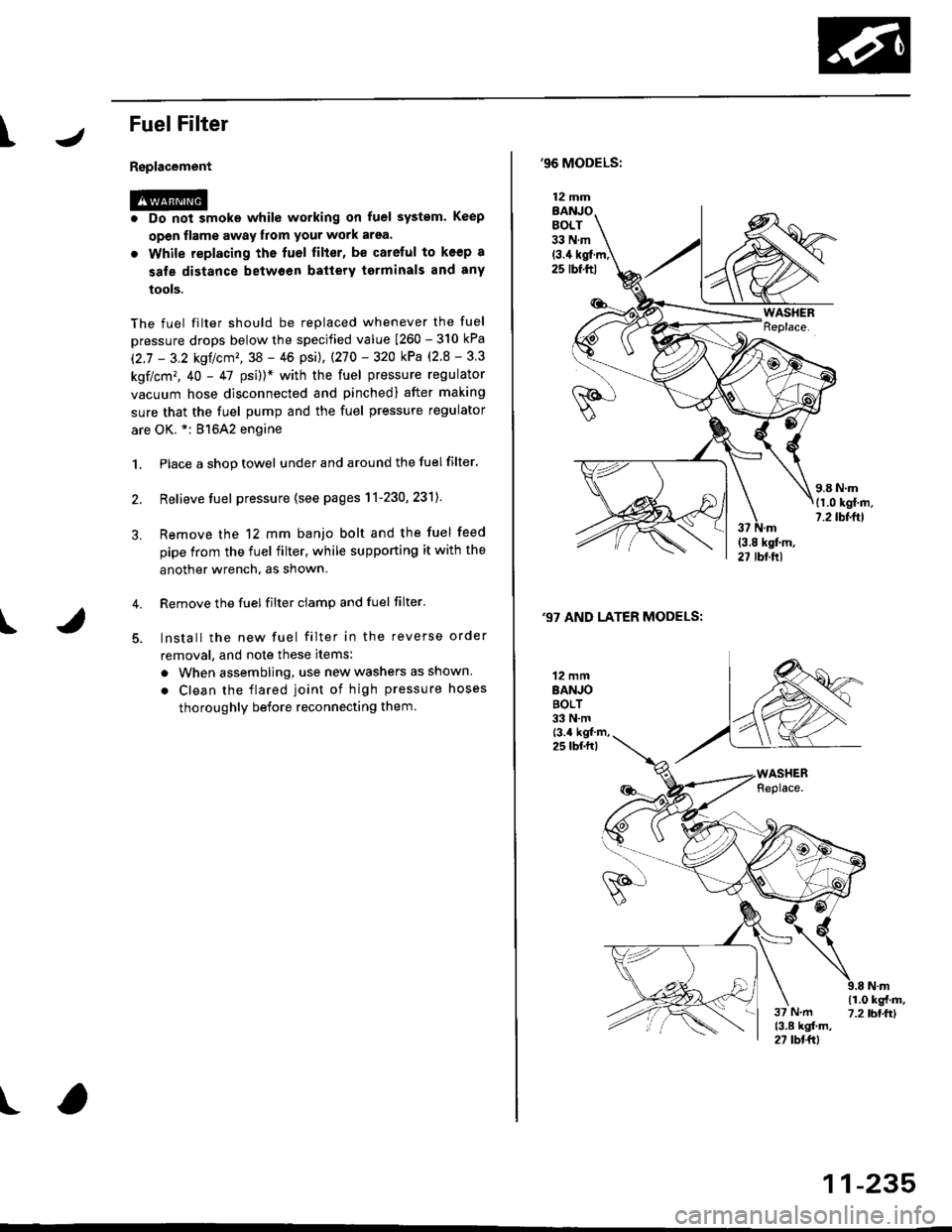
FuelFilter
Replacement
r@. Do not smoke whilc working on fuel system. Keep
open flame away from your work arsa.
. While replacing the tuel filter, be catelul to koep a
sale distance betwoen battery torminals and any
tools.
The fuel filter should be replaced whenever the fuel
pressure drops below the specified value [260 - 310 kPa
12.7 - 3.2 ksl/cm'�,38 - 46 psi), |270 - 320 kPa (2.8 - 3 3
kgf/cm,, 40 - 47 psi))* with the fuel pressure regulator
vacuum hose disconnected and pinchedl after making
sure that the fuel pump and the fuel pressure regulator
are OK. *: 81642 engine
1. Place a shop towel under and around the fuelfilter.
2. Relieve fuel pressure (see pages 11-230,231]-
Remove the 12 mm banjo bolt and the fuel feed
pipe from the fuel filter, while supporting it with the
another wrench, as shown.
Remove the fuel filter ciamp and fuel filter'
lnstall the new fuel filter in the reverse order
removal, and note these items:
a When assembling, use new washers as shown
. Clean the flared joint of high pressure hoses
thoroughly before reconnecting them.
I
,96 MODELS:
(3.4 kgl.m,25 rbf.ftl
,97 AND LATER MODELS:
12 mmBANJOBOLT33 N.m
12 mmBANJOBOLT33 N.mt3.4 kgf m,25 lbf.fr)
\i(o-r
)
11-235