1996 CHRYSLER VOYAGER parking brake
[x] Cancel search: parking brakePage 1555 of 1938
(11) Recheck the fluid level after the transaxle is
at normal operating temperature. The level should be
in the HOT range. Drive the vehicle a minimum of
10 miles.
(12) Raise the vehicle on the hoist.
(13) Remove the pan and clean all sealant from
the pan and transaxle mating surfaces. Clean the
magnet and the inside of the pan.
(14) Separate the filter from the valve body to
allow additional fluid to drain from the transaxle.
Inspect the filter O-ring for any damage and replace
as necessary.
(15) After the transaxle has stopped draining,
reinstall the filter and O-ring.
(16) Apply a 1/8 inch bead of Mopar RTV Sealant
to the mounting flange of the transaxle oil pan.
Apply RTV Sealant to the underside of the attaching
bolts. Attach the oil pan to the transaxle. Tighten the
bolts to 19 N´m (165 in. lbs.).
(17) Lower the vehicle and add 4 Quarts of Mopar
ATF Plus 3 Type 7176 transaxle fluid.
(18) Start the engine and allow it to idle for a min-
imum of one minute. With the parking brake applied,
press your foot on the service brake and cycle the
transaxle from park to all gear positions ending in
neutral or park.
(19) Check the transaxle fluid level and add an
appropriate amount to bring the transaxle fluid level
to 3mm (1/8 in.) below the ADD mark on the dip-
stick.
(20) Recheck the fluid level after the transaxle is
at normal operating temperature. The level should be
in the HOT range.
FLUID DRAIN AND REFILL
(1) Raise vehicle on a hoist (See Group 0, Lubrica-
tion). Place a drain container with a large opening,
under transaxle oil pan.
(2) Loosen pan bolts and tap the pan at one corner
to break it loose allowing fluid to drain, then remove
the oil pan.
(3) Install a new filter and O-ring on bottom of the
valve body.
(4) Clean the oil pan and magnet. Reinstall pan
using new MOPARtRTV sealant. Tighten oil pan
bolts to 19 N´m (165 in. lbs.).
(5) Pour four quarts of MOPARtATF PLUS 3
(Automatic Transmission Fluid) Type 7176 through
the fill tube.
(6) Start engine and allow to idle for at least one
minute. Then, with parking and service brakes
applied, move selector lever momentarily to each
position, ending in the park or neutral position.(7) Add sufficient fluid to bring level to 1/8 inch
below the ADD mark.
CAUTION: Do not overfill transaxle. Do not add oil
if level is between: Lower holes for warm oil
(100ÉF). Upper holes for hot oil (180ÉF).
(8) Recheck fluid level after transaxle is at normal
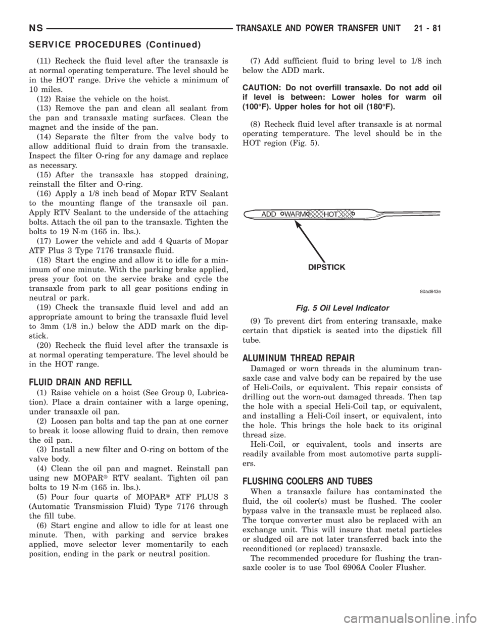
operating temperature. The level should be in the
HOT region (Fig. 5).
(9) To prevent dirt from entering transaxle, make
certain that dipstick is seated into the dipstick fill
tube.
ALUMINUM THREAD REPAIR
Damaged or worn threads in the aluminum tran-
saxle case and valve body can be repaired by the use
of Heli-Coils, or equivalent. This repair consists of
drilling out the worn-out damaged threads. Then tap
the hole with a special Heli-Coil tap, or equivalent,
and installing a Heli-Coil insert, or equivalent, into
the hole. This brings the hole back to its original
thread size.
Heli-Coil, or equivalent, tools and inserts are
readily available from most automotive parts suppli-
ers.
FLUSHING COOLERS AND TUBES
When a transaxle failure has contaminated the
fluid, the oil cooler(s) must be flushed. The cooler
bypass valve in the transaxle must be replaced also.
The torque converter must also be replaced with an
exchange unit. This will insure that metal particles
or sludged oil are not later transferred back into the
reconditioned (or replaced) transaxle.
The recommended procedure for flushing the tran-
saxle cooler is to use Tool 6906A Cooler Flusher.
Fig. 5 Oil Level Indicator
NSTRANSAXLE AND POWER TRANSFER UNIT 21 - 81
SERVICE PROCEDURES (Continued)
Page 1558 of 1938
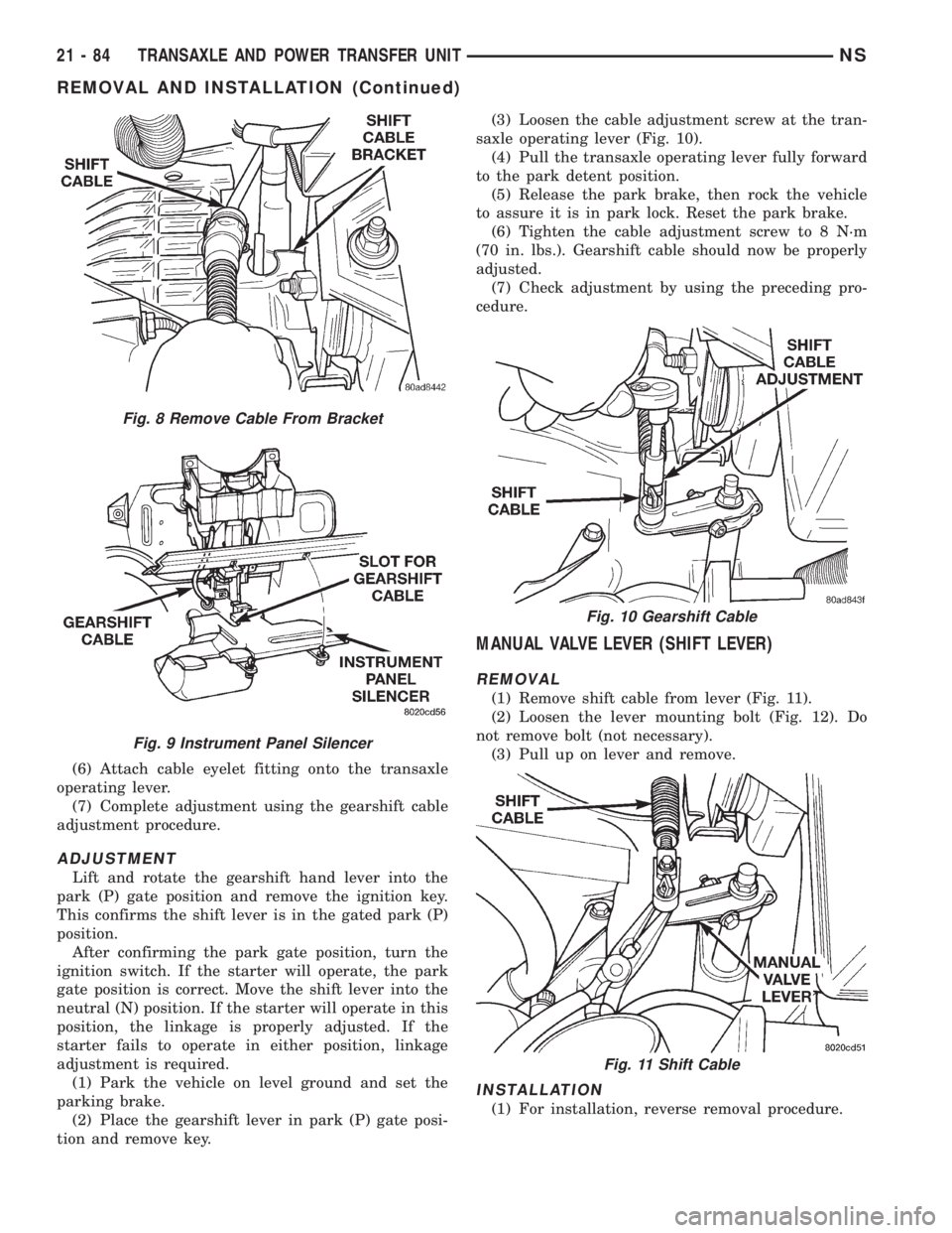
(6) Attach cable eyelet fitting onto the transaxle
operating lever.
(7) Complete adjustment using the gearshift cable
adjustment procedure.
ADJUSTMENT
Lift and rotate the gearshift hand lever into the
park (P) gate position and remove the ignition key.
This confirms the shift lever is in the gated park (P)
position.
After confirming the park gate position, turn the
ignition switch. If the starter will operate, the park
gate position is correct. Move the shift lever into the
neutral (N) position. If the starter will operate in this
position, the linkage is properly adjusted. If the
starter fails to operate in either position, linkage
adjustment is required.
(1) Park the vehicle on level ground and set the
parking brake.
(2) Place the gearshift lever in park (P) gate posi-
tion and remove key.(3) Loosen the cable adjustment screw at the tran-
saxle operating lever (Fig. 10).
(4) Pull the transaxle operating lever fully forward
to the park detent position.
(5) Release the park brake, then rock the vehicle
to assure it is in park lock. Reset the park brake.
(6) Tighten the cable adjustment screw to 8 N´m
(70 in. lbs.). Gearshift cable should now be properly
adjusted.
(7) Check adjustment by using the preceding pro-
cedure.
MANUAL VALVE LEVER (SHIFT LEVER)
REMOVAL
(1) Remove shift cable from lever (Fig. 11).
(2) Loosen the lever mounting bolt (Fig. 12). Do
not remove bolt (not necessary).
(3) Pull up on lever and remove.
INSTALLATION
(1) For installation, reverse removal procedure.
Fig. 8 Remove Cable From Bracket
Fig. 9 Instrument Panel Silencer
Fig. 10 Gearshift Cable
Fig. 11 Shift Cable
21 - 84 TRANSAXLE AND POWER TRANSFER UNITNS
REMOVAL AND INSTALLATION (Continued)
Page 1618 of 1938
(11) Install the oil baffle. Install the proper shim
combination under the bearing cup.
(12) Install the differential bearing retainer. Seal
the retainer to the housing with MopartSilicone
Rubber Adhesive Sealant. Torque bolts to 28 N´m
(250 in. lbs.).
(13) Using Miller Special Tool L-4436-A and an
inch-pound torque wrench, check the turning torque
of the differential (Fig. 299). The turning torque
should be between 5-18 inch-pounds.
NOTE: If turning torque is too high install a .05mm
(.002 inch) thicker shim. If the turning torque is too
low, install a .05mm (.002 inch) thinner shim. Repeat
until 5-18 inch-pounds of turning torque is
obtained.
CLEANING AND INSPECTION
CLEANING VALVE BODY
Prior to removing any transaxle parts, plug all
openings and clean unit, preferably by steam. Clean-
liness through entire disassembly and assembly can-
not be overemphasized. When disassembling, each
part should be washed in a suitable solvent, then
dried by compressed air.Do not wipe parts with
shop towels.All mating surfaces in the transaxles
are accurately machined; therefore, careful handling
of all parts must be exercised to avoid nicks or burrs.
NOTE: Tag all springs, as they are removed, for
reassembly identification.
ADJUSTMENTS
GEARSHIFT CABLE ADJUSTMENT
Lift and rotate the gearshift hand lever into the
park (P) gate position and remove the ignition key.This confirms the shift lever is in the gated park (P)
position.
After confirming the park gate position, turn the
ignition switch. If the starter will operate, the park
gate position is correct. Move the shift lever into the
neutral (N) position. If the starter will operate in this
position, the linkage is properly adjusted. If the
starter fails to operate in either position, linkage
adjustment is required.
(1) Park the vehicle on level ground and set the
parking brake.
(2) Place the gearshift lever in park (P) gate posi-
tion and remove key.
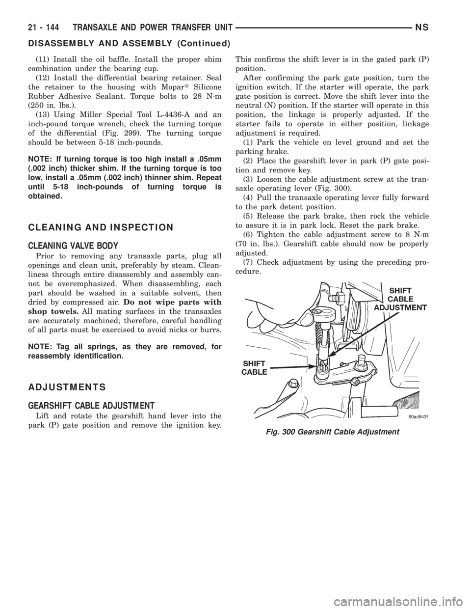
(3) Loosen the cable adjustment screw at the tran-
saxle operating lever (Fig. 300).
(4) Pull the transaxle operating lever fully forward
to the park detent position.
(5) Release the park brake, then rock the vehicle
to assure it is in park lock. Reset the park brake.
(6) Tighten the cable adjustment screw to 8 N´m
(70 in. lbs.). Gearshift cable should now be properly
adjusted.
(7) Check adjustment by using the preceding pro-
cedure.
Fig. 300 Gearshift Cable Adjustment
21 - 144 TRANSAXLE AND POWER TRANSFER UNITNS
DISASSEMBLY AND ASSEMBLY (Continued)
Page 1815 of 1938
BODY COMPONENT SERVICE
INDEX
page page
REMOVAL AND INSTALLATION
GEARSHIFT CONSOLE.................... 3LIFTGATE CHMSL ACCESS PANEL........... 3
REMOVAL AND INSTALLATION
GEARSHIFT CONSOLE
REMOVAL
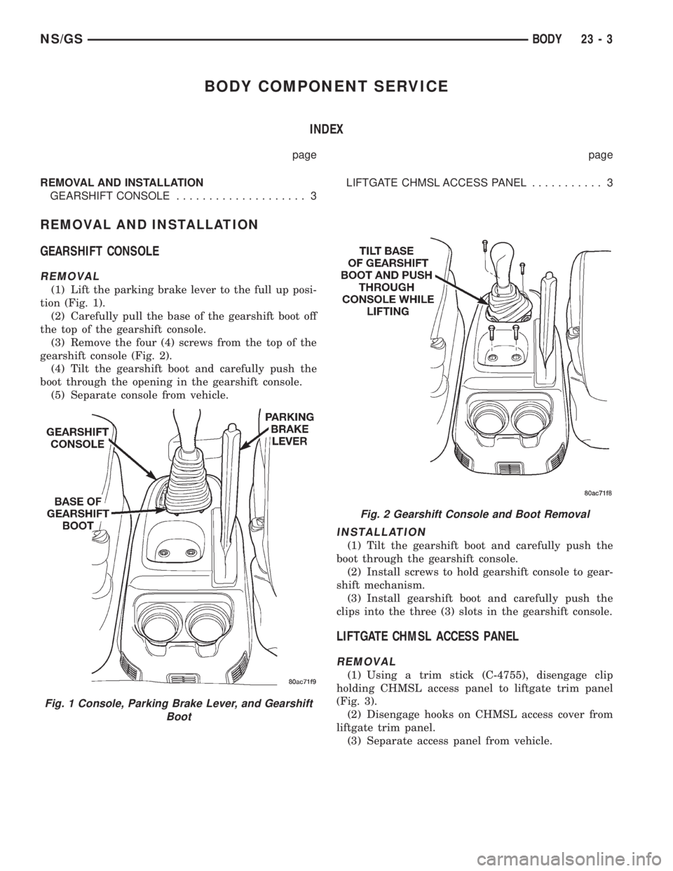
(1) Lift the parking brake lever to the full up posi-
tion (Fig. 1).
(2) Carefully pull the base of the gearshift boot off
the top of the gearshift console.
(3) Remove the four (4) screws from the top of the
gearshift console (Fig. 2).
(4) Tilt the gearshift boot and carefully push the
boot through the opening in the gearshift console.
(5) Separate console from vehicle.
INSTALLATION
(1) Tilt the gearshift boot and carefully push the
boot through the gearshift console.
(2) Install screws to hold gearshift console to gear-
shift mechanism.
(3) Install gearshift boot and carefully push the
clips into the three (3) slots in the gearshift console.
LIFTGATE CHMSL ACCESS PANEL
REMOVAL
(1) Using a trim stick (C-4755), disengage clip
holding CHMSL access panel to liftgate trim panel
(Fig. 3).
(2) Disengage hooks on CHMSL access cover from
liftgate trim panel.
(3) Separate access panel from vehicle.
Fig. 1 Console, Parking Brake Lever, and Gearshift
Boot
Fig. 2 Gearshift Console and Boot Removal
NS/GSBODY 23 - 3
Page 1845 of 1938
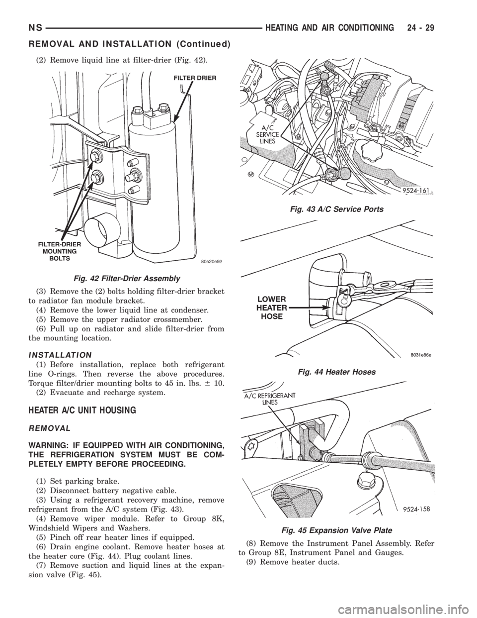
(2) Remove liquid line at filter-drier (Fig. 42).
(3) Remove the (2) bolts holding filter-drier bracket
to radiator fan module bracket.
(4) Remove the lower liquid line at condenser.
(5) Remove the upper radiator crossmember.
(6) Pull up on radiator and slide filter-drier from
the mounting location.
INSTALLATION
(1) Before installation, replace both refrigerant
line O-rings. Then reverse the above procedures.
Torque filter/drier mounting bolts to 45 in. lbs.610.
(2) Evacuate and recharge system.
HEATER A/C UNIT HOUSING
REMOVAL
WARNING: IF EQUIPPED WITH AIR CONDITIONING,
THE REFRIGERATION SYSTEM MUST BE COM-
PLETELY EMPTY BEFORE PROCEEDING.
(1) Set parking brake.
(2) Disconnect battery negative cable.
(3) Using a refrigerant recovery machine, remove
refrigerant from the A/C system (Fig. 43).
(4) Remove wiper module. Refer to Group 8K,
Windshield Wipers and Washers.
(5) Pinch off rear heater lines if equipped.
(6) Drain engine coolant. Remove heater hoses at
the heater core (Fig. 44). Plug coolant lines.
(7) Remove suction and liquid lines at the expan-
sion valve (Fig. 45).(8) Remove the Instrument Panel Assembly. Refer
to Group 8E, Instrument Panel and Gauges.
(9) Remove heater ducts.
Fig. 42 Filter-Drier Assembly
Fig. 43 A/C Service Ports
Fig. 44 Heater Hoses
Fig. 45 Expansion Valve Plate
NSHEATING AND AIR CONDITIONING 24 - 29
REMOVAL AND INSTALLATION (Continued)
Page 1892 of 1938
(2) Hand-start the stud into the expansion valve
and torque to7-11N´m(64-96in.lbs.).
(3) Carefully install the expansion valve to the
sealing plate. Install the two screws and tighten 8 to
14 N´m (70 to 130 in. lbs.) torque.
(4) Carefully install the refrigerant lines and seal-
ing plate to the expansion valve. Install the nut and
tighten 20 to 26 N´m (170 to 230 in. lbs.) torque.
(5) Install the ground wire at dash panel.
(6) Pull generator back into the proper position for
bracket mounting.
(7) Install generator field wire connector.
(8) Install the upper generator bracket.
(9) Install accessory drive belt.
(10) Evacuate and recharge system.
(11) After expansion valve is installed, the system
is charged, and leaks have checked repeat the A/C
performance check.
FILTER-DRIER ASSEMBLY
REMOVAL
WARNING: THE REFRIGERATION SYSTEM MUST
BE COMPLETELY EMPTY BEFORE PROCEEDING
WITH THIS OPERATION.
(1) Recover A/C system refrigerant.
(2) Remove liquid line at filter-drier (Fig. 21).
(3) Remove the (2) bolts holding filter-drier bracket
to radiator fan module bracket.
(4) Remove the lower liquid line at condenser.
(5) Remove the upper radiator crossmember.
(6) Pull up on radiator and slide filter-drier from
the mounting location.
INSTALLATION
(1) Before installation, replace both refrigerant
line O-rings. Then reverse the above procedures.
(2) Evacuate and recharge system.
HEATER A/C UNIT HOUSING
REMOVAL
WARNING: IF EQUIPPED WITH AIR CONDITIONING,
THE REFRIGERATION SYSTEM MUST BE COM-
PLETELY EMPTY BEFORE PROCEEDING.
(1) Set parking brake.
(2) Disconnect battery negative cable.
(3) Using a refrigerant recovery machine, remove
refrigerant from the A/C system.
(4) Remove wiper module. Refer to Group 8K,
Windshield Wipers and Washers.
(5) Drain engine coolant. Remove heater hoses at
the heater core, refer to Heater Hoses Removal and
Installation procedures. Plug coolant lines.(6) Remove suction and liquid lines at the expan-
sion valve (Fig. 27).
(7) Remove the Instrument Panel Assembly. Refer
to Group 8E, Instrument Panel and Systems.
(8) Remove heater ducts.
(9) Disconnect the two upper mounts from the
upper reinforcement and the lower mount from the
tunnel.
(10) Remove the (3) nuts (in the engine compart-
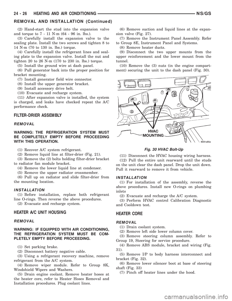
ment) securing the unit to the dash panel (Fig. 30).
(11) Disconnect the HVAC housing wiring harness.
(12) Pull the entire unit rearward until the studs
on the unit clear the dash panel. Drop the unit down.
Pull it rearward to remove it from vehicle.
INSTALLATION
(1) For installation of the assembly, reverse the
above procedures. Install new O-rings on plumbing
inlets
(2) Evacuate and recharge the A/C system.
(3) Perform HVAC control Calibration Diagnostic
and Cooldown test.
HEATER CORE
REMOVAL
(1) Drain coolant system.
(2) Remove left side lower column cover.
(3) Remove steering column assembly. Refer to
Group 19, Steering for service procedure.
(4) Remove ABS module, bracket and wiring (Fig.
31).
(5) Remove I/P to body harness interconnect and
bracket (Fig. 32).
(6) Remove lower silencer boot at base of steering
shaft (Fig. 33)
(7) Pinch off heater lines under the hood.
Fig. 30 HVAC Bolt-Up
24 - 26 HEATING AND AIR CONDITIONINGNS/GS
REMOVAL AND INSTALLATION (Continued)
Page 1920 of 1938
the inlet. This results in maximum vapor flow
through the valve (Fig. 9).
CRANKCASE VENT FILTER
All engines use filtered air to vent the crankcase.
The filtered air is drawn through the resonator
assembly located between the air cleaner and throttle
body.
VEHICLE EMISSION CONTROL INFORMATION
LABEL
All models have a Vehicle Emission Control Infor-
mation (VECI) Label. Chrysler permanently attaches
the label in the engine compartment. It cannot be
removed without defacing information and destroying
the label.
The label contains the vehicle's emission specifica-
tions and vacuum hose routings. All hoses must be
connected and routed according to the label.
DIAGNOSIS AND TESTING
LEAK DETECTION PUMP
Refer to the appropriate Powertrain Diagnostic
Procedures Manual for testing procedures.
PCV VALVE TEST
WARNING: APPLY PARKING BRAKE AND/OR
BLOCK WHEELS BEFORE PERFORMING ANY TEST
OR ADJUSTMENT WITH THE ENGINE OPERATING.
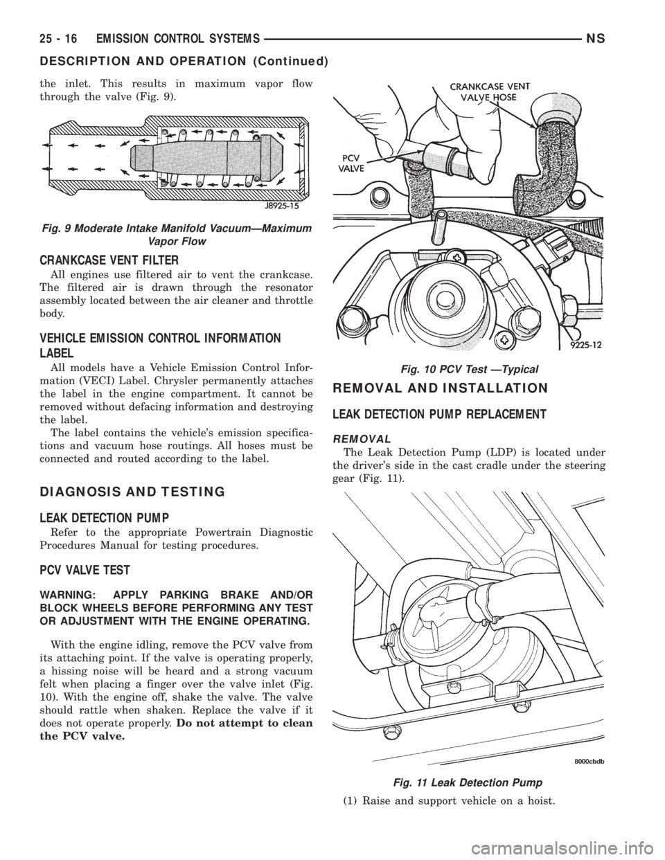
With the engine idling, remove the PCV valve from
its attaching point. If the valve is operating properly,
a hissing noise will be heard and a strong vacuum
felt when placing a finger over the valve inlet (Fig.
10). With the engine off, shake the valve. The valve
should rattle when shaken. Replace the valve if it
does not operate properly.Do not attempt to clean
the PCV valve.
REMOVAL AND INSTALLATION
LEAK DETECTION PUMP REPLACEMENT
REMOVAL
The Leak Detection Pump (LDP) is located under
the driver's side in the cast cradle under the steering
gear (Fig. 11).
(1) Raise and support vehicle on a hoist.
Fig. 9 Moderate Intake Manifold VacuumÐMaximum
Vapor Flow
Fig. 10 PCV Test ÐTypical
Fig. 11 Leak Detection Pump
25 - 16 EMISSION CONTROL SYSTEMSNS
DESCRIPTION AND OPERATION (Continued)
Page 1923 of 1938
the amount of EGR supplied to the engine. This pro-
vides the correct amount of exhaust gas recirculation
for different operating conditions.
This system does not allow EGR at idle. The EGR
systems can operate at all coolant temperatures
above 60ÉF as long as the battery ambient tempera-
ture is above 7ÉF.
DIAGNOSIS AND TESTING
EGR SYSTEM ON-BOARD DIAGNOSTICS
The PCM performs an on-board diagnostic check of
the EGR system. The diagnostic system uses the
electronic EGR transducer for the system tests.
The diagnostic check activates only during selected
engine/driving conditions. When the conditions are
met, the PCM energizes the transducer solenoid to
disable the EGR. The PCM checks for a change in
the heated oxygen sensor signal. If the air-fuel mix-
ture goes lean, the PCM will attempt to enrichen the
mixture. The PCM registers a Diagnostic Trouble
Code (DTC) if the EGR system is not operating cor-
rectly. After registering a DTC, the PCM turns on the
malfunction indicator (Check Engine) lamp after 2
consecutive trips. There are 2 types of failures sensed
by the PCM. The first is a short or open in the elec-
trical solenoid circuit. The second is a mechanical
failure or loss of vacuum. The Malfunction Indicator
Lamp (MIL) indicates the need for service.
If a problem is indicated by the MIL and a DTC for
the EGR system is set, check for proper operation of
the EGR system. Use the System Test, EGR Gas
Flow Test. If the EGR system tests properly, check
the system using the DRB scan tool. Refer to
On-Board Diagnosis sections in this Group. Also,
refer to the DRB scan tool and the appropriate Pow-
ertrain Diagnostics Procedure manual.
EGR SYSTEM TEST
WARNING: APPLY PARKING BRAKE AND/OR
BLOCK WHEELS BEFORE TESTING THE EGR SYS-
TEM.
(1) Check the condition of all EGR system hoses
and tubes for leaks, cracks, kinks and hardening of
rubber hoses. Repair and correct these conditions
before performing any tests.
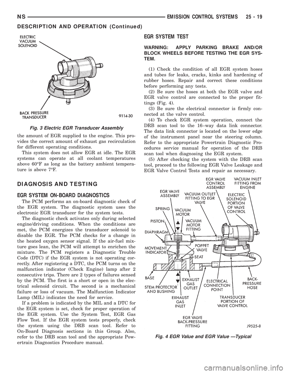
(2) Be sure the hoses at both the EGR valve and
EGR valve control are connected to the proper fit-
tings (Fig. 4).
(3) Be sure the electrical connector is firmly con-
nected at the valve control.
(4) To check EGR system operation, connect the
DRB scan tool to the 16±way data link connector.
The data link connector is located on the lower edge
of the instrument panel near the steering column.
Refer to the appropriate Powertrain Diagnostic Pro-
cedures service manual for operation of the DRB
scan tool when diagnosing the EGR system.
(5) After checking the system with the DRB scan
tool, proceed to the following EGR Valve Leakage and
EGR Valve Control Tests and repair as necessary.
Fig. 3 Electric EGR Transducer Assembly
Fig. 4 EGR Value and EGR Value ÐTypical
NSEMISSION CONTROL SYSTEMS 25 - 19
DESCRIPTION AND OPERATION (Continued)