1996 CHRYSLER VOYAGER center console
[x] Cancel search: center consolePage 877 of 1938

8W-80 CONNECTOR PIN-OUTS
Component Page
A/C Heater Control - C1................8W-80-5
A/C Heater Control - C2................8W-80-5
A/C Compressor Clutch.................8W-80-5
A/C Pressure Transducer (Gas)...........8W-80-6
A/C Pressure Transducer (Diesel).........8W-80-6
A/C Zone Door Actuator.................8W-80-6
Accelerator Pedal Position Sensor (Diesel) . .8W-80-6
Airbag Control Module - C1.............8W-80-6
Airbag Control Module - C2.............8W-80-7
All Wheel Drive Solenoid - C1............8W-80-7
All Wheel Drive Solenoid - C2............8W-80-7
Ambient Air Temperature Sensor.........8W-80-7
Ash Receiver Lamp (LHD)...............8W-80-8
Ash Receiver Lamp (RHD)..............8W-80-8
Automatic Day/Night Mirror.............8W-80-8
B09 HS5D...........................8W-80-9
B09S02.............................8W-80-9
B13AW4............................8W-80-9
B17 LJ01............................8W-80-9
B23P18............................8W-80-10
B23P34............................8W-80-11
B33 E120...........................8W-80-12
B33E36............................8W-80-12
B56 HS5P..........................8W-80-12
B56S02............................8W-80-12
B70E43............................8W-80-13
B75C20............................8W-80-13
B98T08............................8W-80-14
B99T05............................8W-80-14
Back-Up Switch......................8W-80-14
Blend Door Actuator..................8W-80-14
Body Control Module - C1..............8W-80-15
Body Control Module - C2..............8W-80-16
Brake Pressure Switch................8W-80-16
C19EC1 ...........................8W-80-17
Camshaft Position Sensor..............8W-80-17
Center Dome Lamp...................8W-80-17
Center High Mounted Stop Lamp........8W-80-17
Clockspring - C1.....................8W-80-18
Clockspring - C2.....................8W-80-18
Clutch Interlock Switch................8W-80-18
Clutch Interlock Switch Jumper.........8W-80-18
Clutch Switch.......................8W-80-18
Controller Anti-Lock Brake.............8W-80-19
Crank Case Heater...................8W-80-19
Crankshaft Position Sensor.............8W-80-19
D01D B02..........................8W-80-20
D01P B03..........................8W-80-20
D02B01 ...........................8W-80-20
D02 B120 (LHD).....................8W-80-21
D02 B120 (RHD).....................8W-80-21
Data Link Connector..................8W-80-22Component Page
Downstream Heated Oxygen Sensor......8W-80-22
Driver Door Arm/Disarm Switch.........8W-80-22
Driver Door Courtesy Lamp............8W-80-22
Driver Door Lock Motor................8W-80-23
Driver Door Lock Switch...............8W-80-23
Driver Heated Seat Back...............8W-80-23
Driver Heated Seat Cushion............8W-80-23
Driver Heated Seat Module.............8W-80-23
Driver Heated Seat Switch.............8W-80-24
Driver Power Mirror - C1..............8W-80-24
Driver Power Mirror - C2..............8W-80-24
Driver Power Seat Switch..............8W-80-25
Driver Power Window Switch...........8W-80-25
Driver Seat Front Vertical Motor.........8W-80-25
Driver Seat Horizontal Motor...........8W-80-25
Driver Seat Rear Vertical Motor.........8W-80-26
Driver Seat Recliner Motor.............8W-80-26
Driver Window Motor.................8W-80-26
E40RF3 ...........................8W-80-26
E69F09............................8W-80-27
E78F02............................8W-80-27
E95 B107...........................8W-80-27
E96 B108...........................8W-80-28
E97 B106...........................8W-80-28
EGR Solenoid (2.4L MTX/3.3L/3.8L)......8W-80-28
EGR Solenoid (Diesel).................8W-80-28
Electric Wiper De-Icer - C1.............8W-80-29
Electric Wiper De-Icer - C2.............8W-80-29
Engine Coolant Temperature Sensor
(Diesel)..........................8W-80-29
Engine Coolant Temperature Sensor
(Gas)............................8W-80-29
Engine Oil Pressure Switch.............8W-80-29
Engine Speed Sensor (Diesel)...........8W-80-30
Evap Leak Detection Pump
(Except Built-Up-Export).............8W-80-30
Evap/Purge Solenoid..................8W-80-30
Evaporator Temperature Sensor.........8W-80-30
Flexible Fuel Sensor..................8W-80-30
Front Blower Motor...................8W-80-31
Front Blower Motor Resistor Block.......8W-80-31
Front Cigar Lighter/Power Outlet........8W-80-31
Front Reading Lamps/Switch...........8W-80-32
Front Reading Lamps/Switch
(Overhead Console).................8W-80-32
Front Washer Motor..................8W-80-32
Fuel Heater.........................8W-80-32
Fuel Injector No. 1 (2.0L/2.4L)...........8W-80-33
Fuel Injector No. 1 (3.3L/3.8L)...........8W-80-33
Fuel Injector No. 2 (2.0L/2.4L)...........8W-80-33
Fuel Injector No. 2 (3.3L/3.8L)...........8W-80-33
Fuel Injector No. 3 (2.0L/2.4L)...........8W-80-33
NS/GS8W - 80 CONNECTOR PIN-OUTS 8W - 80 - 1
Page 878 of 1938

Component Page
Fuel Injector No. 3 (3.3L/3.8L)...........8W-80-34
Fuel Injector No. 4 (2.0L/2.4L)...........8W-80-34
Fuel Injector No. 4 (3.3L/3.8L)...........8W-80-34
Fuel Injector No. 5 (3.3L/3.8L)...........8W-80-34
Fuel Injector No. 6 (3.3L/3.8L)...........8W-80-34
Fuel Pump Module...................8W-80-35
Fuel Tank Module....................8W-80-35
G200..............................8W-80-35
G300..............................8W-80-36
G301 (Diesel)........................8W-80-37
G301 (Gas).........................8W-80-37
G302..............................8W-80-38
G400..............................8W-80-38
Generator..........................8W-80-38
Glove Box Lamp.....................8W-80-39
Glow Plug Relay.....................8W-80-39
HS6D S02..........................8W-80-39
HS6P S02..........................8W-80-39
Headlamp Switch - C1.................8W-80-39
Headlamp Switch - C2.................8W-80-40
Headlamp Washer....................8W-80-40
High Note Horn......................8W-80-40
Hood Ajar Switch.....................8W-80-41
Horn/Speed Control Switch.............8W-80-41
Idle Air Control Motor.................8W-80-41
Ignition Coil Pack (2.0L/2.4L)...........8W-80-41
Ignition Coil Pack (3.3L/3.8L)...........8W-80-41
Ignition Switch - C1..................8W-80-42
Ignition Switch - C2..................8W-80-42
Ignition Switch - C3..................8W-80-42
Instrument Cluster...................8W-80-42
Intake Air Temperature Sensor..........8W-80-43
Intake Air Temperature/Manifold
Absolute Pressure Sensor............8W-80-43
J02A L15...........................8W-80-43
J03A L16...........................8W-80-43
Junction Block - C1...................8W-80-44
Junction Block - C2...................8W-80-45
Junction Block - C3...................8W-80-46
Junction Block - C4...................8W-80-47
Key-In Halo Lamp....................8W-80-48
Key-In Switch.......................8W-80-48
Knock Sensor........................8W-80-48
Left Combination Relay................8W-80-48
Left Door Speaker....................8W-80-48
Left Fog Lamp (Built-Up-Export)........8W-80-49
Left Fog Lamp (Except Built-Up-Export). . .8W-80-49
Left Front Panel Speaker..............8W-80-49
Left Front Park/Turn Signal Lamp
(Built-Up-Export)..................8W-80-49
Left Front Park/Turn Signal Lamp
(Except Built-Up-Export)............8W-80-49
Left Front Speaker...................8W-80-49
Left Front Wheel Speed Sensor..........8W-80-50Component Page
Left Headlamp (Built-Up-Export)........8W-80-50
Left Headlamp (Except Built-Up-Export) . .8W-80-50
Left Headlamp Leveling Motor
(Built-Up-Export)..................8W-80-50
Left High Headlamp (Chrysler)
(Except Built-Up-Export).............8W-80-50
Left Liftgate Flood Lamp...............8W-80-51
Left Low Headlamp (Chrysler)
(Except Built-Up-Export).............8W-80-51
Left Mid Reading Lamp................8W-80-51
Left Rear Door Ajar Switch.............8W-80-51
Left Rear Lamp Assembly
(Built-Up-Export)..................8W-80-51
Left Rear Lamp Assembly
(Except Built-Up-Export).............8W-80-51
Left Rear Pillar Speaker...............8W-80-52
Left Rear Reading Lamp...............8W-80-52
Left Rear Sliding Door Contacts.........8W-80-52
Left Rear Speaker....................8W-80-52
Left Rear Vent Motor (LHD)............8W-80-52
Left Rear Vent Motor (RHD)............8W-80-53
Left Rear Wheel Speed Sensor..........8W-80-53
Left Repeater Lamp...................8W-80-53
Left Stop/Turn Signal Relay............8W-80-53
Left Visor/Vanity Mirror Lamps.........8W-80-53
License Lamp.......................8W-80-54
Liftgate Ajar Switch..................8W-80-54
Liftgate Arm/Disarm Switch............8W-80-54
Liftgate Lock Motor...................8W-80-54
Low Coolant Level Switch..............8W-80-54
Low Note Horn......................8W-80-54
Low Washer Fluid Switch..............8W-80-54
Manifold Absolute Pressure Sensor.......8W-80-55
Memory Power Seat Switch.............8W-80-55
Memory Seat Front Vertical Motor.......8W-80-55
Memory Seat Front Vertical
Position Sensor....................8W-80-55
Memory Seat Horizontal Motor..........8W-80-55
Memory Seat Horizontal Position Sensor . .8W-80-56
Memory Seat Rear Vertical Motor........8W-80-56
Memory Seat Rear Vertical
Position Sensor....................8W-80-56
Memory Seat Recliner Motor............8W-80-56
Memory Seat Recliner Position Sensor. . . .8W-80-56
Memory Seat/Mirror Module - C1........8W-80-57
Memory Seat/Mirror Module - C2........8W-80-57
Memory Seat/Mirror Module - C3........8W-80-58
Memory Set Switch...................8W-80-58
Message Center (LHD)................8W-80-58
Message Center (RHD)................8W-80-59
Mode Door Actuator...................8W-80-59
Multi-Function Switch.................8W-80-59
Needle Movement Sensor..............8W-80-60
Output Shaft Speed Sensor.............8W-80-60
Overhead Console....................8W-80-60
8W - 80 - 2 8W - 80 CONNECTOR PIN-OUTSNS/GS
Page 969 of 1938

Component/
GroundColor Location Fig.
Message Center BL Rear of
Message
Center11
Mode Door
ActuatorBK LT Side of
HVAC15
Multi Function
SwitchBK Rear of Switch 11
Name Brand
Speaker RelayLT/GY LT of Steering
Column11
Needle
Movement
SensorBK Back of
Generator8
Output Shaft
Speed SensorGY Front of
Transmission7, 9
Overhead
ConsoleRD Front of
Console15
P18 GY RT of Steering
Column12
P25 BK RT of I.P
Center Stack10
P30 BK RT Side of
HVAC10
P34 GY RT of Steering
Column12
P50 NAT Right Side of
HVAC Unit
Taped to
Harness10
Park Brake
SwitchBK Top of Park
Brake13
Park/Neutral
Positon SwitchBK Front of
TransmissionN/S
Passenger
AirbagYL Rear of Airbag 11
PDC C1 NAT Bottom of PDC 2
PDC C2 OR Bottom of PDC 2
PDC C3 DK/
GNBottom of PDC 2
PDC C4 BK Bottom of PDC 2
PDC C5 LT/GY Bottom of PDC 2
PDC C6 LT/GN Bottom of PDC 3
PDC C7 LT/GY Bottom of PDC 3
PDC C8 BL Bottom of PDC 3
Power Folding
Mirror SwitchBK At Switch N/SComponent/
GroundColor Location Fig.
Power Mirror
SwitchBK Rear of Switch 11
Power Steering
Pressure SwitchBK RT Side of
Engine
CompartmentN/S
Powertrain
Control Module
C1BK LT Fender Side
Shield3
Powertrain
Control Module
C2BK LT Fender Side
Shield3
Radiator Fan
No.1BK At Motor N/S
Radiator Fan
No.2BK At Motor N/S
Radiator Fan
Solid State
RelayBK LT Front Frame
Rail3
Radio C1 GY Rear of Radio 11
Radio C2 BK Rear of Radio 11
Radio C3 BK Rear of Radio 11
Radio Choke LT/GY Rear of Radio N/S
Rear A/C-
Heater UnitLT/GN RT Quarter
Panel22
Rear Blower
Front Control
SwitchBK Rear of Switch 11
Rear Blower
Rear Control
SwitchBK At Switch N/S
Rear Cigar
Lighter/Power
OutletBK LT Quarter
Panel21
Rear Dome
LampBK At Lamp N/S
Rear Washer
MotorBK Bottom of
Reservior4
Rear Window
DefoggerBK On Liftgate 21
Rear Wiper
MotorBK At Motor 21
Recirculation
Door ActuatorNAT RT Side of
HVAC15
Remote Keyless
Entry ModuleRD Top Left of I.P. 11
RF3 BK At Radiator Fan N/S
NS/GS8W - 90 CONNECTOR/GROUND LOCATIONS 8W - 90 - 5
DESCRIPTION AND OPERATION (Continued)
Page 998 of 1938

Component/
GroundColor Location Fig.
Left Rear
Reading LampGY At Lamp 17
Left Rear
Sliding Door
ContactBK LT B-Pillar 14
Left Rear
Sliding Door
Lock MotorBK At Motor N/S
Left Rear
SpeakerBK At Speaker 21
Left Rear Vent
MotorNAT At Motor 21
Left Rear Wheel
Speed SensorGY Center Rear of
Floor Pan16
Left Repeater
LampGY At Lamp N/S
Left Speed
Control SwitchLeft Side of
Steering Wheel
Pad11
Left Stop/Turn
Signal RelayBK LT Quarter
PanelN/S
Left Visor/Vanity
LampBK At Lamp 17
License Lamp GY At Lamps 23
Liftgate Ajar
SwitchBK At Latch 23
Liftgate
Arm/Disarm
SwitchGY At Key Cylinder 23
Liftgate Lock
MotorBK At Motor 23
LJ01 BK LT Quarter
Panel21
Low Note Horn BK LT Frame Rail 4
Low Washer
Fluid Level
SensorBK Bottom of
Reservior4
MAP Sensor
2.4LBK On Intake N/S
MAP Sensor
3.3L, 3.8LBK Near Throttle
Body9
Memort
Seat/Mirror
ModuleBK RT Front of
Floor Pan16
Memory Set
SwitchBL At Switch 19Component/
GroundColor Location Fig.
Message Center BL Rear of
Message
Center11
Mode Door
ActuatorBK LT Side of
HVAC15
Multi Function
SwitchBK Rear of Switch 11
Name Brand
Speaker RelayLT/GY LT of Steering
ColumnN/S
Output Shaft
Speed SensorGY Front of
Transmission7, 9
Overhead
ConsoleRD Front of
Console17
P18 GY RT of Steering
Column12
P30 BK RT Side of
HVAC10
P34 GY RT of Steering
Column12
P50 NAT Right Side of
HVAC Taped to
Harness10
Park Brake
SwitchNAT Top of Park
BrakeN/S
Park/Neutral
Positon SwitchBK Front of
TransmissionN/S
Passenger
AirbagYL Rear of Airbag 11
PDC C1 NAT Bottom of PDC 2
PDC C2 OR Bottom of PDC 2
PDC C3 DK/
GNBottom of PDC 2
PDC C4 BK Bottom of PDC 2
PDC C5 LT/GY Bottom of PDC 2
PDC C6 LT/GN Bottom of PDC 3
PDC C7 LT/GY Bottom of PDC 3
PDC C8 BL Bottom of PDC 3
Power Folding
Mirror SwitchBK At Switch N/S
Power Mirror
SwitchBK Rear of Switch 11
Power Steering
Pressure SwitchBK RT Side of
Engine
CompartmentN/S
8W - 90 - 34 8W - 90 CONNECTOR/GROUND LOCATIONSNS/GS
DESCRIPTION AND OPERATION (Continued)
Page 1369 of 1938

FUEL SYSTEMÐ2.5L DIESEL ENGINE/2.0L GAS ENGINE
CONTENTS
page page
FUEL DELIVERY SYSTEMÐ2.0L ENGINE.... 28
FUEL DELIVERY SYSTEMÐ2.5L DIESEL
ENGINE.............................. 3
FUEL INJECTION SYSTEMÐ2.0L ENGINE . . . 32FUEL INJECTION SYSTEMÐ2.5L DIESEL
ENGINE............................. 43
GENERAL INFORMATION.................. 1
GENERAL INFORMATION
INDEX
page page
GENERAL INFORMATION
FUEL REQUIREMENTSÐ2.0L ENGINE....... 2
FUEL REQUIREMENTSÐ2.5L DIESEL........ 2GASOLINE/OXYGENATE BLENDS........... 2
INTRODUCTIONÐ2.0L ENGINE............. 2
INTRODUCTIONÐ2.5L DIESEL............. 1
GENERAL INFORMATION
INTRODUCTIONÐ2.5L DIESEL
Certain components of the fuel system on the 2.5L
diesel engine are controlled by the Bosch Engine con-
troller which is a Powertrain Control Module (PCM).
Refer to Powertrain Control Module in the Fuel
Injection SystemÐ2.5L Diesel Engine section of this
group for a list of items controlled by the PCM. The
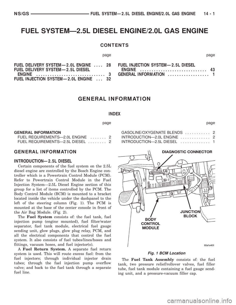
Body Control Module (BCM) is mounted to a bracket
located inside the vehicle under the dashpanel to the
left of the steering column (Fig. 1). The PCM is
mounted at the base of the center console in front of
the Air Bag Module. (Fig. 2).
TheFuel Systemconsists of: the fuel tank, fuel
injection pump (engine mounted), fuel filter/water
separator, fuel tank module, electrical fuel gauge
sending unit, glow plugs, glow plug relay, PCM, and
all the electrical components that control the fuel
system. It also consists of fuel tubes/lines/hoses and
fittings, vacuum hoses, and fuel injector(s).
AFuel Return System.A separate fuel return
system is used. This will route excess fuel: from the
fuel injectors; through individual injector drain
tubes; through the fuel injection pump overflow
valve; and back to the fuel tank through a separate
fuel line.TheFuel Tank Assemblyconsists of: the fuel
tank, two pressure relief/rollover valves, fuel filler
tube, fuel tank module containing a fuel gauge send-
ing unit, and a pressure-vacuum filler cap.
Fig. 1 BCM Location
NS/GSFUEL SYSTEMÐ2.5L DIESEL ENGINE/2.0L GAS ENGINE 14 - 1
Page 1756 of 1938

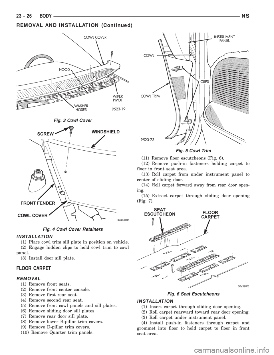
INSTALLATION
(1) Place cowl trim sill plate in position on vehicle.
(2) Engage hidden clips to hold cowl trim to cowl
panel.
(3) Install door sill plate.
FLOOR CARPET
REMOVAL
(1) Remove front seats.
(2) Remove front center console.
(3) Remove first rear seat.
(4) Remove second rear seat.
(5) Remove front cowl panels and sill plates.
(6) Remove sliding door sill plates.
(7) Remove rear door sill plate.
(8) Remove lower B-pillar trim covers.
(9) Remove D-pillar trim covers.
(10) Remove Quarter trim panels.(11) Remove floor escutcheons (Fig. 6).
(12) Remove push-in fasteners holding carpet to
floor in front seat area.
(13) Roll carpet from under instrument panel to
center of sliding door.
(14) R
oll carpet forward away from rear door open-
ing.
(15) Extract carpet through sliding door opening
(Fig. 7).
INSTALLATION
(1) Insert carpet through sliding door opening.
(2) Roll carpet rearward toward rear door opening.
(3) Roll carpet under instrument panel.
(4) Install push-in fasteners through carpet and
grommet into floor to hold carpet to floor in front
seat area.
Fig. 3 Cowl Cover
Fig. 4 Cowl Cover Retainers
Fig. 5 Cowl Trim
Fig. 6 Seat Escutcheons
23 - 26 BODYNS
REMOVAL AND INSTALLATION (Continued)
Page 1757 of 1938

CAUTION: Ensure that the correct fasteners are
installed in the proper locations. Damage to the fuel
tank may result.
(5) Install floor escutcheons.
(6) Install Quarter trim panels.
(7) Install D-pillar trim covers.
(8) Install lower B-pillar trim covers.
(9) Install rear door sill plate.
(10) Install sliding door sill plates.
(11) Install front cowl panels and sill plates.
(12) Install second rear seat.
(13) Install first rear seat.
(14) Install front center console.
(15) Install front seats.
FRONT DOOR
CAUTION: If the hinge pin must be removed from
the hinge, do not reuse the original pin. The struc-
tural integrity of the hinge would be reduced. Verify
availability prior to proceeding if hinge pins are to
be removed.
NOTE: The retaining clips used on the door hinge
pins are not to be re-used. Verify availability prior to
proceeding if clips are to be removed.
REMOVAL
(1) Open front door.
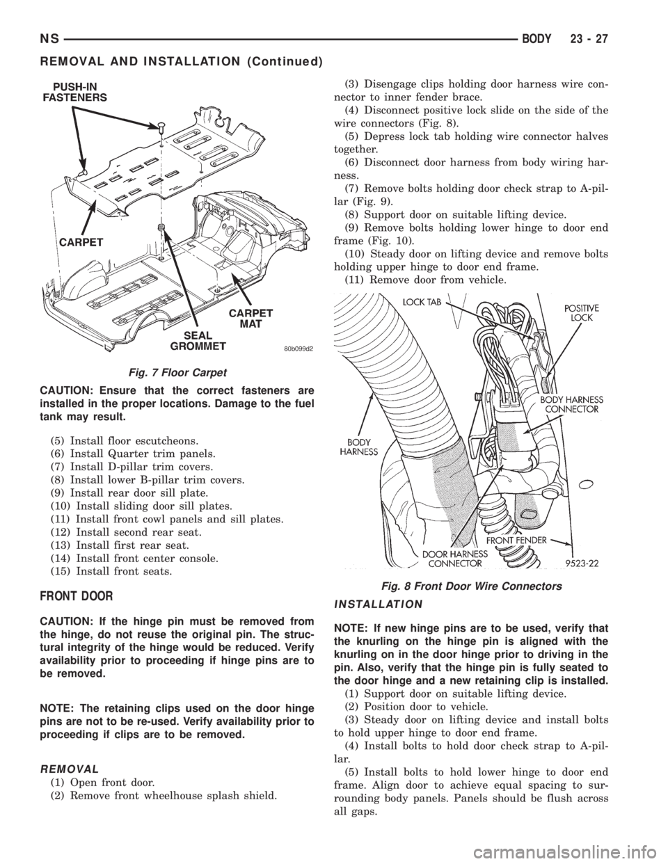
(2) Remove front wheelhouse splash shield.(3) Disengage clips holding door harness wire con-
nector to inner fender brace.
(4) Disconnect positive lock slide on the side of the
wire connectors (Fig. 8).
(5) Depress lock tab holding wire connector halves
together.
(6) Disconnect door harness from body wiring har-
ness.
(7) Remove bolts holding door check strap to A-pil-
lar (Fig. 9).
(8) Support door on suitable lifting device.
(9) Remove bolts holding lower hinge to door end
frame (Fig. 10).
(10) Steady door on lifting device and remove bolts
holding upper hinge to door end frame.
(11) Remove door from vehicle.
INSTALLATION
NOTE: If new hinge pins are to be used, verify that
the knurling on the hinge pin is aligned with the
knurling on in the door hinge prior to driving in the
pin. Also, verify that the hinge pin is fully seated to
the door hinge and a new retaining clip is installed.
(1) Support door on suitable lifting device.
(2) Position door to vehicle.
(3) Steady door on lifting device and install bolts
to hold upper hinge to door end frame.
(4) Install bolts to hold door check strap to A-pil-
lar.
(5) Install bolts to hold lower hinge to door end
frame. Align door to achieve equal spacing to sur-
rounding body panels. Panels should be flush across
all gaps.
Fig. 7 Floor Carpet
Fig. 8 Front Door Wire Connectors
NSBODY 23 - 27
REMOVAL AND INSTALLATION (Continued)