1996 CHRYSLER VOYAGER engine oil
[x] Cancel search: engine oilPage 1349 of 1938
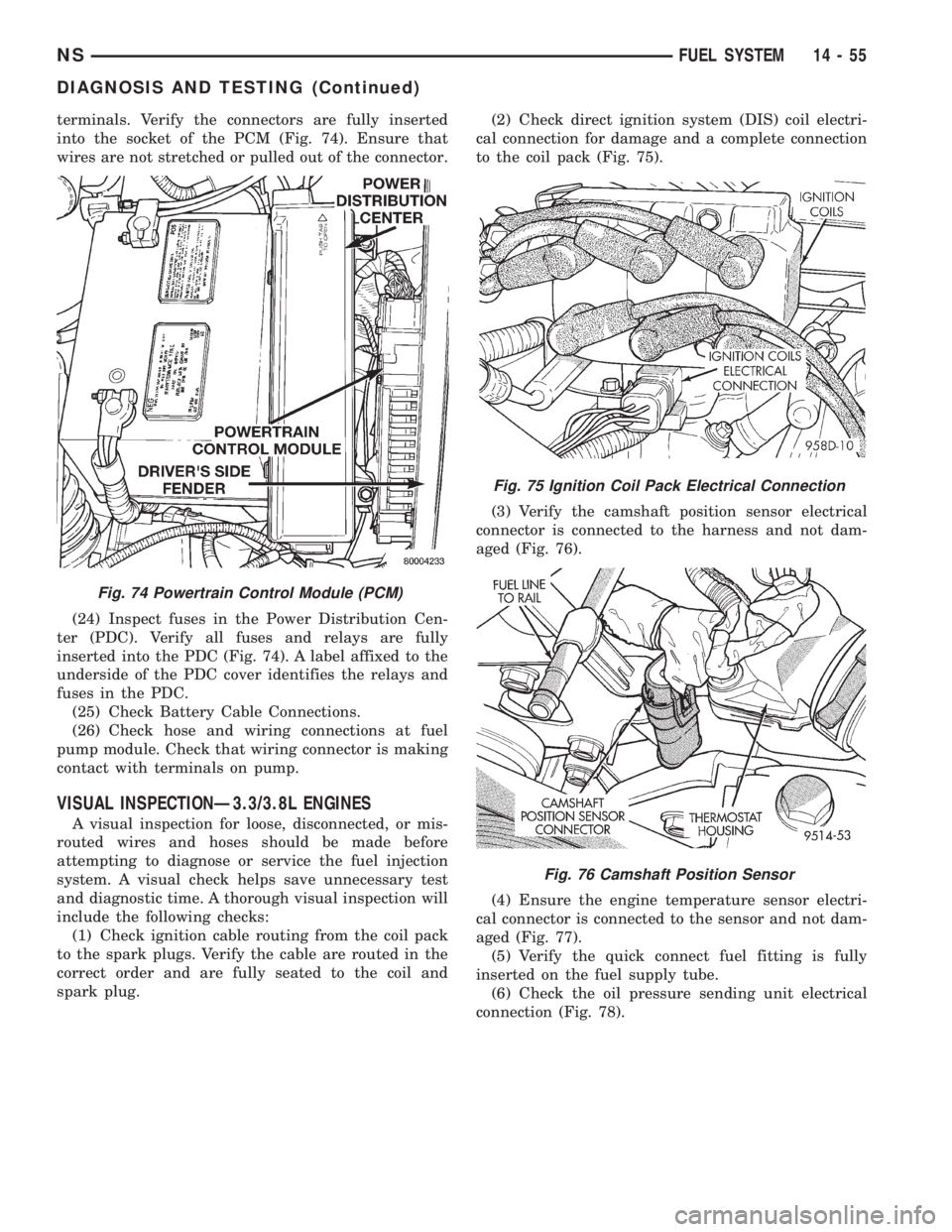
terminals. Verify the connectors are fully inserted
into the socket of the PCM (Fig. 74). Ensure that
wires are not stretched or pulled out of the connector.
(24) Inspect fuses in the Power Distribution Cen-
ter (PDC). Verify all fuses and relays are fully
inserted into the PDC (Fig. 74). A label affixed to the
underside of the PDC cover identifies the relays and
fuses in the PDC.
(25) Check Battery Cable Connections.
(26) Check hose and wiring connections at fuel
pump module. Check that wiring connector is making
contact with terminals on pump.
VISUAL INSPECTIONÐ3.3/3.8L ENGINES
A visual inspection for loose, disconnected, or mis-
routed wires and hoses should be made before
attempting to diagnose or service the fuel injection
system. A visual check helps save unnecessary test
and diagnostic time. A thorough visual inspection will
include the following checks:
(1) Check ignition cable routing from the coil pack
to the spark plugs. Verify the cable are routed in the
correct order and are fully seated to the coil and
spark plug.(2) Check direct ignition system (DIS) coil electri-
cal connection for damage and a complete connection
to the coil pack (Fig. 75).
(3) Verify the camshaft position sensor electrical
connector is connected to the harness and not dam-
aged (Fig. 76).
(4) Ensure the engine temperature sensor electri-
cal connector is connected to the sensor and not dam-
aged (Fig. 77).
(5) Verify the quick connect fuel fitting is fully
inserted on the fuel supply tube.
(6) Check the oil pressure sending unit electrical
connection (Fig. 78).
Fig. 74 Powertrain Control Module (PCM)
Fig. 75 Ignition Coil Pack Electrical Connection
Fig. 76 Camshaft Position Sensor
NSFUEL SYSTEM 14 - 55
DIAGNOSIS AND TESTING (Continued)
Page 1350 of 1938
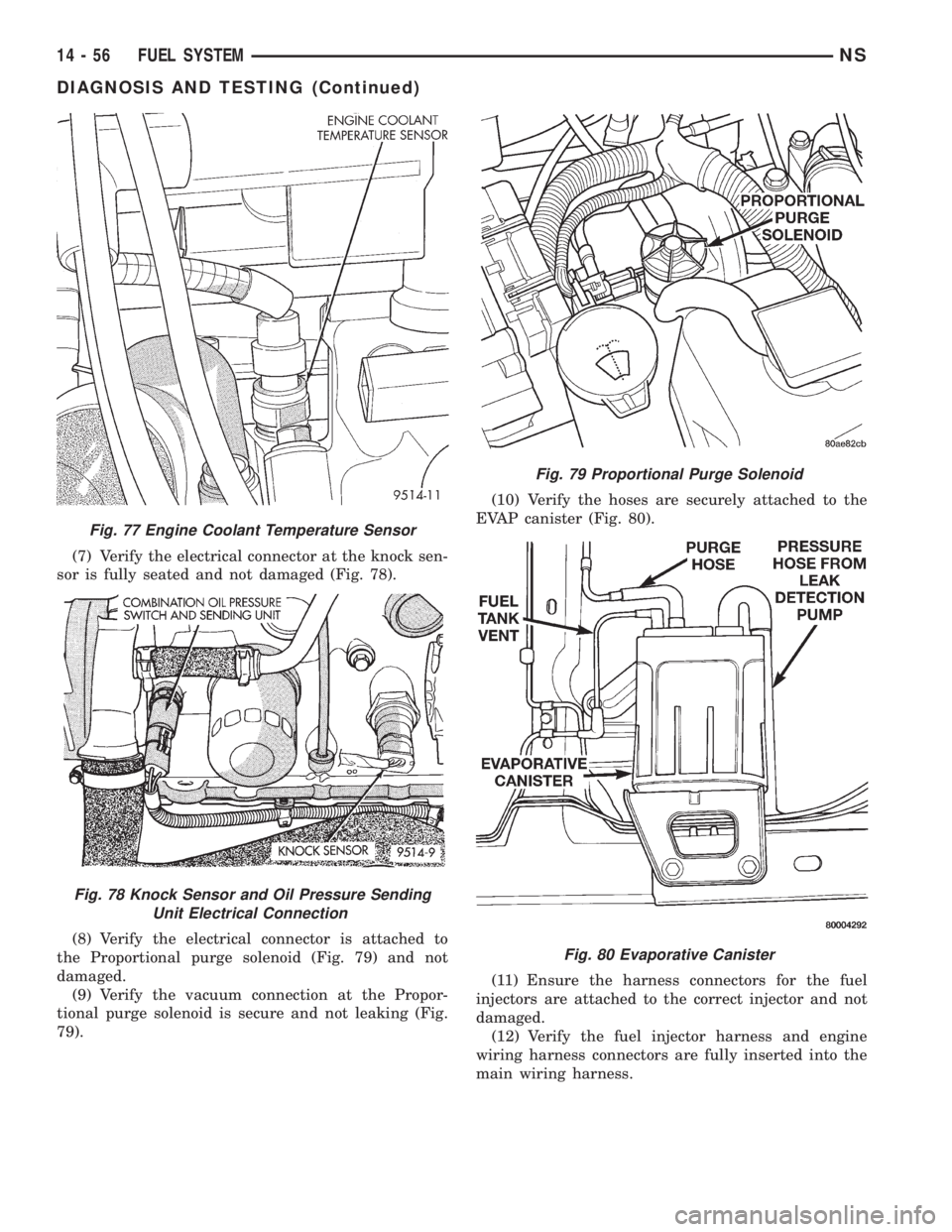
(7) Verify the electrical connector at the knock sen-
sor is fully seated and not damaged (Fig. 78).
(8) Verify the electrical connector is attached to
the Proportional purge solenoid (Fig. 79) and not
damaged.
(9) Verify the vacuum connection at the Propor-
tional purge solenoid is secure and not leaking (Fig.
79).(10) Verify the hoses are securely attached to the
EVAP canister (Fig. 80).
(11) Ensure the harness connectors for the fuel
injectors are attached to the correct injector and not
damaged.
(12) Verify the fuel injector harness and engine
wiring harness connectors are fully inserted into the
main wiring harness.
Fig. 77 Engine Coolant Temperature Sensor
Fig. 78 Knock Sensor and Oil Pressure Sending
Unit Electrical Connection
Fig. 79 Proportional Purge Solenoid
Fig. 80 Evaporative Canister
14 - 56 FUEL SYSTEMNS
DIAGNOSIS AND TESTING (Continued)
Page 1354 of 1938
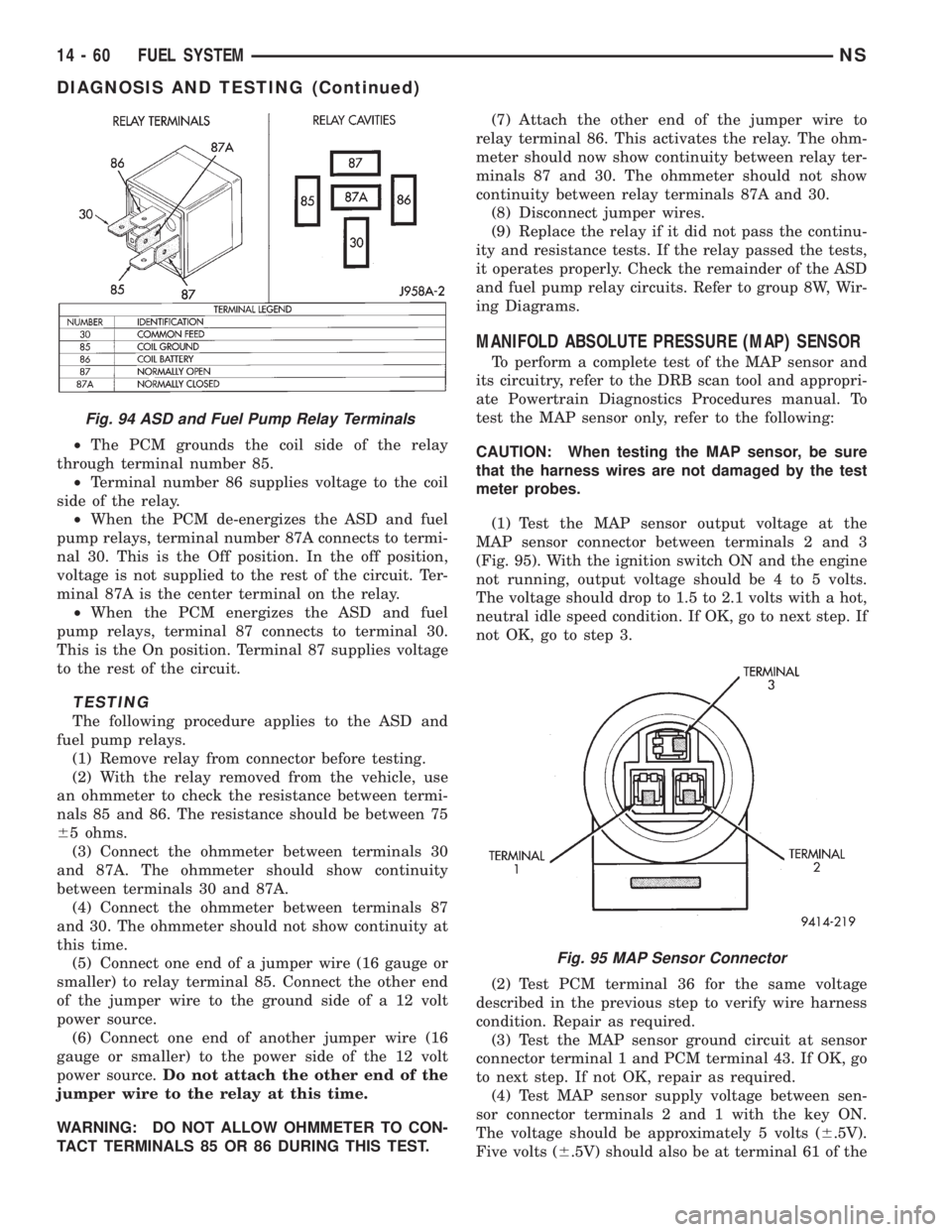
²The PCM grounds the coil side of the relay
through terminal number 85.
²Terminal number 86 supplies voltage to the coil
side of the relay.
²When the PCM de-energizes the ASD and fuel
pump relays, terminal number 87A connects to termi-
nal 30. This is the Off position. In the off position,
voltage is not supplied to the rest of the circuit. Ter-
minal 87A is the center terminal on the relay.
²When the PCM energizes the ASD and fuel
pump relays, terminal 87 connects to terminal 30.
This is the On position. Terminal 87 supplies voltage
to the rest of the circuit.
TESTING
The following procedure applies to the ASD and
fuel pump relays.
(1) Remove relay from connector before testing.
(2) With the relay removed from the vehicle, use
an ohmmeter to check the resistance between termi-
nals 85 and 86. The resistance should be between 75
65 ohms.
(3) Connect the ohmmeter between terminals 30
and 87A. The ohmmeter should show continuity
between terminals 30 and 87A.
(4) Connect the ohmmeter between terminals 87
and 30. The ohmmeter should not show continuity at
this time.
(5) Connect one end of a jumper wire (16 gauge or
smaller) to relay terminal 85. Connect the other end
of the jumper wire to the ground side of a 12 volt
power source.
(6) Connect one end of another jumper wire (16
gauge or smaller) to the power side of the 12 volt
power source.Do not attach the other end of the
jumper wire to the relay at this time.
WARNING: DO NOT ALLOW OHMMETER TO CON-
TACT TERMINALS 85 OR 86 DURING THIS TEST.(7) Attach the other end of the jumper wire to
relay terminal 86. This activates the relay. The ohm-
meter should now show continuity between relay ter-
minals 87 and 30. The ohmmeter should not show
continuity between relay terminals 87A and 30.
(8) Disconnect jumper wires.
(9) Replace the relay if it did not pass the continu-
ity and resistance tests. If the relay passed the tests,
it operates properly. Check the remainder of the ASD
and fuel pump relay circuits. Refer to group 8W, Wir-
ing Diagrams.
MANIFOLD ABSOLUTE PRESSURE (MAP) SENSOR
To perform a complete test of the MAP sensor and
its circuitry, refer to the DRB scan tool and appropri-
ate Powertrain Diagnostics Procedures manual. To
test the MAP sensor only, refer to the following:
CAUTION: When testing the MAP sensor, be sure
that the harness wires are not damaged by the test
meter probes.
(1) Test the MAP sensor output voltage at the
MAP sensor connector between terminals 2 and 3
(Fig. 95). With the ignition switch ON and the engine
not running, output voltage should be 4 to 5 volts.
The voltage should drop to 1.5 to 2.1 volts with a hot,
neutral idle speed condition. If OK, go to next step. If
not OK, go to step 3.
(2) Test PCM terminal 36 for the same voltage
described in the previous step to verify wire harness
condition. Repair as required.
(3) Test the MAP sensor ground circuit at sensor
connector terminal 1 and PCM terminal 43. If OK, go
to next step. If not OK, repair as required.
(4) Test MAP sensor supply voltage between sen-
sor connector terminals 2 and 1 with the key ON.
The voltage should be approximately 5 volts (6.5V).
Five volts (6.5V) should also be at terminal 61 of the
Fig. 94 ASD and Fuel Pump Relay Terminals
Fig. 95 MAP Sensor Connector
14 - 60 FUEL SYSTEMNS
DIAGNOSIS AND TESTING (Continued)
Page 1392 of 1938
(4) Raise vehicle on hoist.
(5) Disconnect both the fuel fill and fuel vent rub-
ber hoses at the fuel tank.
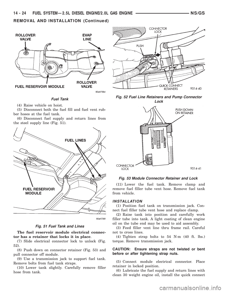
(6) Disconnect fuel supply and return lines from
the steel supply line (Fig. 51).
The fuel reservoir module electrical connec-
tor has a retainer that locks it in place.
(7) Slide electrical connector lock to unlock (Fig.
52).
(8) Push down on connector retainer (Fig. 53) and
pull connector off module.
(9) Use a transmission jack to support fuel tank.
Remove bolts from fuel tank straps.
(10) Lower tank slightly. Carefully remove filler
hose from tank.(11) Lower the fuel tank. Remove clamp and
remove fuel filler tube vent hose. Remove fuel tank
from vehicle.
INSTALLATION
(1) Position fuel tank on transmission jack. Con-
nect fuel filler tube vent hose and replace clamp.
(2) Raise tank into position and carefully work
filler tube into tank. A light coating of clean engine
oil on the tube end may be used to aid assembly.
(3) Feed filler vent line thru frame rail. Careful
not to cross lines.
(4) Tighten strap bolts to 54 N´m (40 ft. lbs.)
torque. Remove transmission jack.
CAUTION: Ensure straps are not twisted or bent
before or after tightening strap nuts.
(5) Connect module electrical connector. Place
retainer in locked position.
(6) Lubricate the fuel supply and return lines with
clean 30 weight engine oil, install the quick connect
Fuel Tank
Fig. 51 Fuel Tank and Lines
Fig. 52 Fuel Line Retainers and Pump Connector
Lock
Fig. 53 Module Connector Retainer and Lock
14 - 24 FUEL SYSTEMÐ2.5L DIESEL ENGINE/2.0L GAS ENGINENS/GS
REMOVAL AND INSTALLATION (Continued)
Page 1398 of 1938
FUEL LEVEL SENSORÐ2.0L ENGINE
Refer to the Fuel Pump Inlet Strainer for the 2.4/
3.0/3.3/3.8L engines under Removal and Installation
in the Fuel Delivery System section of group 14 for
more information.
FUEL TANKÐ2.0L ENGINE
Refer to the Fuel Tank for the 2.4/3.0/3.3/3.8L
engines under Removal and Installation in the Fuel
Delivery System section of group 14 for more infor-
mation.
FUEL INJECTORS
REMOVAL
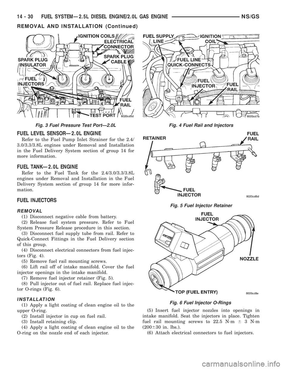
(1) Disconnect negative cable from battery.
(2) Release fuel system pressure. Refer to Fuel
System Pressure Release procedure in this section.
(3) Disconnect fuel supply tube from rail. Refer to
Quick-Connect Fittings in the Fuel Delivery section
of this group.
(4) Disconnect electrical connectors from fuel injec-
tors (Fig. 4).
(5) Remove fuel rail mounting screws.
(6) Lift rail off of intake manifold. Cover the fuel
injector openings in the intake manifold.
(7) Remove fuel injector retainer (Fig. 5).
(8) Pull injector out of fuel rail. Replace fuel injec-
tor O-rings (Fig. 6).
INSTALLATION
(1) Apply a light coating of clean engine oil to the
upper O-ring.
(2) Install injector in cup on fuel rail.
(3) Install retaining clip.
(4) Apply a light coating of clean engine oil to the
O-ring on the nozzle end of each injector.(5) Insert fuel injector nozzles into openings in
intake manifold. Seat the injectors in place. Tighten
fuel rail mounting screws to 22.5 N´m63 N´m
(200630 in. lbs.).
(6) Attach electrical connectors to fuel injectors.
Fig. 3 Fuel Pressure Test PortÐ2.0LFig. 4 Fuel Rail and Injectors
Fig. 5 Fuel Injector Retainer
Fig. 6 Fuel Injector O-Rings
14 - 30 FUEL SYSTEMÐ2.5L DIESEL ENGINE/2.0L GAS ENGINENS/GS
REMOVAL AND INSTALLATION (Continued)
Page 1399 of 1938
(7) Connect fuel supply tube to fuel rail. Refer to
Quick Connect Fittings in the Fuel Delivery Section
of this Group.
ACCELERATOR PEDAL
Refer to the Accelerator Pedal for the 2.4/3.0/.3.3/
3.8L engines under Removal and Installation in the
Fuel Delivery section of group 14 for more informa-
tion.
TORQUE SPECIFICATION
DESCRIPTION TORQUE
Accelerator Pedal to
Dash Nuts..............12N´m(105 in. lbs.)
Fuel Pump Module Locknut....58N´m(43ft.lbs.)
Fuel Tank Strap Bolts.........54N´m(40ftlbs.)
Fuel Rail Bolts.............23N´m(195 in. lbs.)
Ignition Coil Mounting Bolts . . . 11 N´m (95 in. lbs.)
Intake Manifold Bolts........11N´m(95in.lbs.)
Throttle Control Shield.......5.6N´m(50in.lbs.)
NS/GSFUEL SYSTEMÐ2.5L DIESEL ENGINE/2.0L GAS ENGINE 14 - 31
REMOVAL AND INSTALLATION (Continued)
Page 1400 of 1938
FUEL INJECTION SYSTEMÐ2.0L ENGINE
INDEX
page page
GENERAL INFORMATION
INTRODUCTIONÐ2.0L ENGINE............ 32
MODES OF OPERATIONÐ2.0L ENGINE..... 32
DESCRIPTION AND OPERATION
AIR CONDITIONING (A/C) RELAYÐPCM
OUTPUTÐ2.0L ENGINE................ 35
AIR CONDITIONING PRESSURE
TRANSDUCERÐPCM INPUTÐ
2.0L ENGINE......................... 33
AIR CONDITIONING SWITCH SENSEÐ
PCM INPUTÐ2.0L ENGINE.............. 33
AUTOMATIC SHUTDOWN (ASD) SENSEÐ
PCM INPUTÐ2.0L ENGINE.............. 33
AUTOMATIC SHUTDOWN RELAYÐ
PCM OUTPUTÐ2.0L ENGINE............ 35
BATTERY VOLTAGEÐPCM INPUTÐ
2.0L ENGINE......................... 33
CAMSHAFT POSITION SENSORÐ
PCM INPUTÐ2.0L ENGINE.............. 33
CRANKSHAFT POSITION SENSORÐ
PCM INPUTÐ2.0L ENGINE.............. 33
DATA LINK CONNECTORÐPCM OUTPUTÐ
2.0L ENGINE......................... 35
ELECTRONIC EGR TRANSDUCERÐ
PCM OUTPUTÐ2.0L ENGINE............ 35
ENGINE COOLANT TEMPERATURE SENSORÐ
PCM INPUTÐ2.0L ENGINE.............. 33
FUEL INJECTORSÐPCM OUTPUTÐ
2.0L ENGINE......................... 35
FUEL PUMP RELAYÐPCM OUTPUTÐ
2.0L ENGINE......................... 35
GENERATOR FIELDÐPCM OUTPUTÐ
2.0L ENGINE......................... 35
HEATED OXYGEN SENSORÐPCM INPUTÐ
2.0L ENGINE......................... 33
IDLE AIR CONTROL MOTORÐPCM OUTPUTÐ
2.0L ENGINE......................... 35
IGNITION COILÐPCM OUTPUTÐ
2.0L ENGINE......................... 36KNOCK SENSORÐPCM INPUTÐ
2.0L ENGINE......................... 34
MALFUNCTION INDICATOR (CHECK ENGINE)
LAMPÐPCM OUTPUTÐ2.0L ENGINE...... 36
MANIFOLD ABSOLUTE PRESSURE
(MAP SENSOR)ÐPCM INPUTÐ
2.0L ENGINE......................... 34
POWERTRAIN CONTROL MODULEÐ
2.0L ENGINE......................... 33
RADIATOR FAN CONTROL MODULEÐ
PCM OUTPUTÐ2.0L ENGINE............ 36
SPEED CONTROL SOLENOIDSÐ
PCM OUTPUTÐ2.0L ENGINE............ 36
SPEED CONTROLÐPCM INPUTÐ
2.0L ENGINE......................... 34
STARTER RELAYÐPCM OUTPUTÐ
2.0L ENGINE......................... 35
SYSTEM DIAGNOSISÐ2.0L ENGINE........ 33
TACHOMETERÐPCM OUTPUTÐ
2.0L ENGINE......................... 36
THROTTLE BODYÐ2.0L ENGINE.......... 36
THROTTLE POSITION SENSOR/ IDLE AIR
CONTROL MOTORÐPCM INPUTÐ
2.0L ENGINE......................... 35
DIAGNOSIS AND TESTING
ASD AND FUEL PUMP RELAYSÐ
2.0L ENGINE......................... 39
CAMSHAFT AND CRANKSHAFT
POSITION SENSOR................... 40
ENGINE COOLANT TEMPERATURE
SENSOR............................ 40
KNOCK SENSORÐ2.0L ENGINE........... 40
MANIFOLD ABSOLUTE PRESSURE
(MAP) SENSORÐ2.0L ENGINE........... 39
THROTTLE BODY MINIMUM AIR FLOW..... 41
THROTTLE POSITION SENSOR........... 40
VISUAL INSPECTIONÐSOHC............. 36
SPECIFICATIONS
TORQUE............................. 42
GENERAL INFORMATION
INTRODUCTIONÐ2.0L ENGINE
Refer to the Introduction for 2.4/3.0/3.3/3.8L
engines under General Information in the Fuel Injec-
tion System section of group 14 for more information.
MODES OF OPERATIONÐ2.0L ENGINE
Refer to the Modes of Operation for 2.4/3.0/3.3/3.8L
engines under General Information in the Fuel Injec-
tion System section of group 14 for more information.
14 - 32 FUEL SYSTEMÐ2.5L DIESEL ENGINE/2.0L GAS ENGINENS/GS
Page 1404 of 1938
IGNITION COILÐPCM OUTPUTÐ2.0L ENGINE
Refer to the Ignition Coil for 2.4/3.0/3.3/3.8L
engines under Description and Operation in the Fuel
Injection System section of group 14 for more infor-
mation.
MALFUNCTION INDICATOR (CHECK ENGINE)
LAMPÐPCM OUTPUTÐ2.0L ENGINE
Refer to the Malfunction Indicator Lamp for 2.4/
3.0/3.3/3.8L engines under Description and Operation
in the Fuel Injection System section of group 14 for
more information.
RADIATOR FAN CONTROL MODULEÐPCM
OUTPUTÐ2.0L ENGINE
Refer to the Radiator Fan Control Module for 2.4/
3.0/3.3/3.8L engines under Description and Operation
in the Fuel Injection System section of group 14 for
more information.
SPEED CONTROL SOLENOIDSÐPCM OUTPUTÐ
2.0L ENGINE
Refer to the Speed Control Solenoids for 2.4/3.0/3.3/
3.8L engines under Description and Operation in the
Fuel Injection System section of group 14 for more
information.
TACHOMETERÐPCM OUTPUTÐ2.0L ENGINE
Refer to the Tachometer for 2.4/3.0/3.3/3.8L engines
under Description and Operation in the Fuel Injec-
tion System section of group 14 for more information.
THROTTLE BODYÐ2.0L ENGINE
Refer to the Throttle Body for 2.4/3.0/3.3/3.8L
engines under Description and Operation in the Fuel
Injection System section of group 14 for more infor-
mation.
DIAGNOSIS AND TESTING
VISUAL INSPECTIONÐSOHC
Before diagnosing or servicing the fuel injection
system, perform a visual inspection for loose, discon-
nected, or misrouted wires and hoses. A thorough
visual inspection that includes the following checks
saves unnecessary test and diagnostic time.
(1) Inspect the battery connections. Clean corroded
terminals.
(2) Check the 2 PCM 40-way connector for
stretched wires on pushed out terminals
(3) Open the Power Distribution Center (PDC).
Check for blown fuses. Ensure the relays and fuses
are fully seated in the PDC. A label on the underside
of the PDC cover shows the locations of each relay
and fuse.
(4) Verify the throttle cable operates freely.
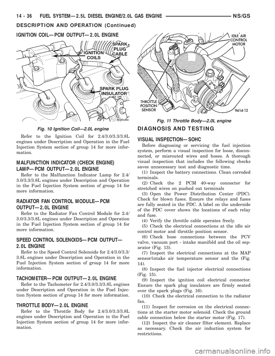
(5) Check the electrical connections at the idle air
control motor and throttle position sensor.
(6) Check hose connections between the PCV
valve, vacuum port - intake manifold and the oil sep-
arator (Fig. 13).
(7) Inspect the electrical connections at the MAP
sensor/intake air temperature sensor and the (Fig.
14).
(8) Inspect the fuel injector electrical connections
(Fig. 15).
(9) Inspect the ignition coil electrical connector.
Ensure the spark plug insulators are firmly seated
over the spark plugs (Fig. 16).
(10) Check the electrical connection to the radiator
fan.
(11) Inspect for corrosion on the electrical connec-
tions at the starter motor solenoid. Check the ground
cable connection below the starter motor (Fig. 17).
(12) Inspect the air cleaner filter element. Replace
as necessary. Check the air induction system for
restrictions.
Fig. 10 Ignition CoilÐ2.0L engine
Fig. 11 Throttle BodyÐ2.0L engine
14 - 36 FUEL SYSTEMÐ2.5L DIESEL ENGINE/2.0L GAS ENGINENS/GS
DESCRIPTION AND OPERATION (Continued)