1996 CHRYSLER VOYAGER turn signal bulb
[x] Cancel search: turn signal bulbPage 495 of 1938

BULB APPLICATION
INDEX
page page
GENERAL INFORMATION
INTRODUCTION....................... 17
CLEANING AND INSPECTION
HEADLAMP CLEANING.................. 17SPECIFICATIONS
EXTERIOR LAMP BULBS................. 17
INTERIOR LAMP BULBS................. 17
GENERAL INFORMATION
INTRODUCTION
The following Bulb Application Tables list the lamp
title on the left side of the column and trade number
or part number on the right.
CAUTION: Do not use bulbs that have a higher
candle power than the bulb listed in the Bulb Appli-
cation Table. Damage to lamp can result.
Do not touch halogen bulbs with fingers or other
possibly oily surfaces. Bulb life will be reduced.
If a halogen bulb is contaminated with oil, clean
bulb with denatured alcohol or ammonia based sol-
vent.
CLEANING AND INSPECTION
HEADLAMP CLEANING
This vehicle is equipped with plastic headlights
that are lighter and less susceptible to stone break-
age than glass headlights.
This plastic is not as scratch resistant as glass and
therefore a different lens cleaning procedures must
be followed.
To minimize the possibility of scratching the lenses
and reducing light output, avoid wiping with a dry
cloth. To remove road dirt, wash with a mild soap
solution followed by rinsing with water.
Do not use abrasive cleaning components, solvents,
steel wool or other aggressive material to clean the
lenses.
SPECIFICATIONS
EXTERIOR LAMP BULBS
LAMP BULB
Back-up.............................P21W
CHMSL (Non-Solar Tint)................P21W
CHMSL (Solar Tint)....................R10WLAMP BULB
Fog Lamp..............................H3
Headlamp..............................H4
License Plate..........................C5W
Front Turn Signal....................PY21W
Citylight..............................T4W
Front Side Repeater.....................T4W
Tail, Stop...........................P21/5W
Rear Turn Signal......................P21W
Rear Fog Lamp........................P21W
INTERIOR LAMP BULBS
LAMP BULB
ABS ................................PC194
AirBag .............................PC194
Alarm Set (Security/Immobilzer)..........PC194
Brake Warning.......................PC194
Center/Rear Reading Lamps...............578
Center/Rear Dome Lamps.................579
Cruise Indicator.......................PC194
Door Ajar Indicator....................PC194
Engine Compartment Lamps...............579
Engine Temp Indicator.................PC194
Front Door Courtesy......................567
Glove Box Lamp.........................194
Glow Plug Indicator (Diesel Engine Only) . . . PC194
High Beam Indicator...................PC194
Instrument Cluster....................PC194
IP/Ash Tray (Left Hand Drive Only).........161
Liftgate Flood Lamps.....................567
Liftgate Ajar Indicator...................PC74
Low Coolant Level (Diesel Engine Only).....PC74
Low Fuel Indicator....................PC194
Low Volts Warning.....................PC74
Low Washer Fluid......................PC74
Oil Pressure Indicator..................PC194
O/H Console Reading Lamps...............579
Seat Belt Indicator (Except Diesel).........PC74
Service Engine Soon...................PC194
Turn Signal..........................PC194
Visor Vanity Lamp...................6501966
NS/GSLAMPS 8L - 17
Page 520 of 1938

access the SKIS for initialization, or by the dealer
technician to access the system for service. The
SKIM also stores in its memory the Vehicle Identifi-
cation Number (VIN), which it learns through a CCD
data bus message from the PCM during initializa-
tion.
The SKIM and the PCM both use software that
includes a rolling code algorithm strategy, which
helps to reduce the possibility of unauthorized SKIS
disarming. The rolling code algorithm ensures secu-
rity by preventing an override of the SKIS through
the unauthorized substitution of the SKIM or the
PCM. However, the use of this strategy also means
that replacement of either the SKIM or the PCM
units will require a system initialization procedure to
restore system operation.
When the ignition switch is turned to the On or
Start positions, the SKIM transmits an RF signal to
excite the Smart Key transponder. The SKIM then
listens for a return RF signal from the transponder
of the Smart Key that is inserted in the ignition lock
cylinder. If the SKIM receives an RF signal with
valid ªSecret Keyº and transponder identification
codes, the SKIM sends a ªvalid keyº message to the
PCM over the CCD data bus. If the SKIM receives
an invalid RF signal or no response, it sends ªinvalid
keyº messages to the PCM. The PCM will enable or
disable engine operation based upon the status of the
SKIM messages.
The SKIM also sends messages to the instrument
cluster over the CCD data bus network to control the
SKIS indicator lamp. The SKIM sends messages to
the instrument cluster to turn the lamp on for about
three seconds when the ignition switch is turned to
the On position as a bulb test. After completion of
the bulb test, the SKIM sends bus messages to keep
the lamp off for a duration of about one second. Then
the SKIM sends messages to turn the lamp on or off
based upon the results of the SKIS self-tests. If the
SKIS indicator lamp comes on and stays on after the
bulb test, it indicates that the SKIM has detected a
system malfunction and/or that the SKIS has become
inoperative.
If the SKIM detects an invalid key when the igni-
tion switch is turned to the On position, it sends
messages to the instrument cluster to flash the SKIS
indicator lamp. The SKIM can also send messages to
the instrument cluster to flash the lamp and to gen-
erate a single audible chime tone.
For diagnosis or initialization of the SKIM and the
PCM, a DRB scan tool and the proper Diagnostic
Procedures manual are required. The SKIM cannot
be repaired and, if faulty or damaged, the unit must
be replaced.SMART KEY IMMOBILIZER TRANSPONDER
The Smart Key Immobilizer System (SKIS) uses a
transponder that is integral to each of the two igni-
tion keys that are supplied with the vehicle when it
is shipped from the factory. The transponder chip is
insulated within a nylon mount inserted in the head
of the key, and invisible beneath a molded rubber cap
(Fig. 1).
Each Smart Key transponder has a unique tran-
sponder identification code programmed into it by the
manufacturer. The Smart Key Immobilizer Module
(SKIM) has a unique ªSecret Keyº code programmed
into it by the manufacturer. When a Smart Key tran-
sponder is programmed into the memory of the
SKIM, the SKIM learns the transponder identifica-
tion code from the transponder, and the transponder
learns the ªSecret Keyº code from the SKIM. Each of
these codes is stored within the transponder and in
the nonvolatile memory of the SKIM. Therefore,
blank keys for the SKIS must be programmed by and
into the SKIM, in addition to being cut to match the
mechanical coding of the ignition lock cylinder. See
Smart Key Immobilizer System Transponder Pro-
gramming in this group for more information.
The Smart Key transponder is within the range of
the SKIM transceiver antenna ring when it is
inserted in the ignition lock cylinder. When the igni-
tion switch is turned to the Start or On positions, the
SKIM transceiver issues a Radio Frequency (RF) sig-
nal that excites the transponder chip. The transpon-
der chip responds by issuing an RF signal containing
its transponder identification code and the ªSecret
Keyº code. The SKIM transceiver compares the tran-
sponder codes with the codes stored in its memory to
Fig. 1 Smart Key Immobilizer Transponder
8Q - 2 VEHICLE THEFT/SECURITY SYSTEMSNS/GS
DESCRIPTION AND OPERATION (Continued)
Page 1340 of 1938
Shutdown (ASD) RelayÐPCM Output in this section
for relay operation.
TORQUE CONVERTER CLUTCH SOLENOIDÐPCM
OUTPUT
Three-speed automatic transaxles use a torque con-
verter clutch solenoid. The PCM controls the engage-
ment of the torque converter clutch through the
solenoid. The torque converter clutch is engaged only
in direct drive mode. Refer to Group 21 for transaxle
information.
MALFUNCTION INDICATOR (CHECK ENGINE)
LAMPÐPCM OUTPUT
The PCM supplies the malfunction indicator (check
engine) lamp on/off signal to the instrument panel
through the CCD Bus. The CCD Bus is a communi-
cations port. Various modules use the CCD Bus to
exchange information.
The Check Engine lamp comes on each time the
ignition key is turned ON and stays on for 3 seconds
as a bulb test.
The Malfunction Indicator Lamp (MIL) stays on
continuously, when the PCM has entered a Limp-In
mode or identified a failed emission component. Dur-
ing Limp-in Mode, the PCM attempts to keep the
system operational. The MIL signals the need for
immediate service. In limp-in mode, the PCM com-
pensates for the failure of certain components that
send incorrect signals. The PCM substitutes for the
incorrect signals with inputs from other sensors.
If the PCM detects active engine misfire severe
enough to cause catalyst damage, it flashes the MIL.
At the same time the PCM also sets a Diagnostic
Trouble Code (DTC).
For signals that can trigger the MIL (Check
Engine Lamp) refer to Group 25, On-Board
Dianostics.
SOLID STATE FAN RELAYÐPCM OUTPUT
The radiator fan runs at a variable speed depend-
ing on coolant temperature and A/C system pressure.
The radiator fan circuit contains a Solid State Fan
Relay (SSFR). Refer to the Group 8W for a circuit
schematic.
A 5 volt signal is supplied to the SSFR. The PCM
provides a pulsed ground for the SSFR. Depending
upon the amount of pulse on time, the SSFR puts out
a proportional voltage to the fan motor at the lower
speed. For instance, if the on time is 30 percent, then
the voltage to the fan motor will be 3.6 volts.
When engine coolant reaches approximately 102ÉC
(215ÉF) the PCM grounds the SSFR relay. If engine
coolant reaches 207ÉC (225ÉF) the PCM grounds the
high speed ground relay and high speed fan relay. If
the fan operates at high speed, the PCM de-energizes
the high speed relay and high speed ground relay
when coolant temperature drops to approximately
101ÉC (214ÉF). When coolant temperature drops to
101ÉC (214ÉF) the fan operates at low speed. The
PCM de-energizes the low speed relay when coolant
temperature drops to approximately 93ÉC (199ÉF).
Also, when the air conditioning pressure switch
closes, the fan operates at high speed. The air condi-
tioning switch closes at 285 psi610 psi. When air
conditioning pressure drops approximately 40 psi, the
pressure switch opens and the fan operates at low
speed.
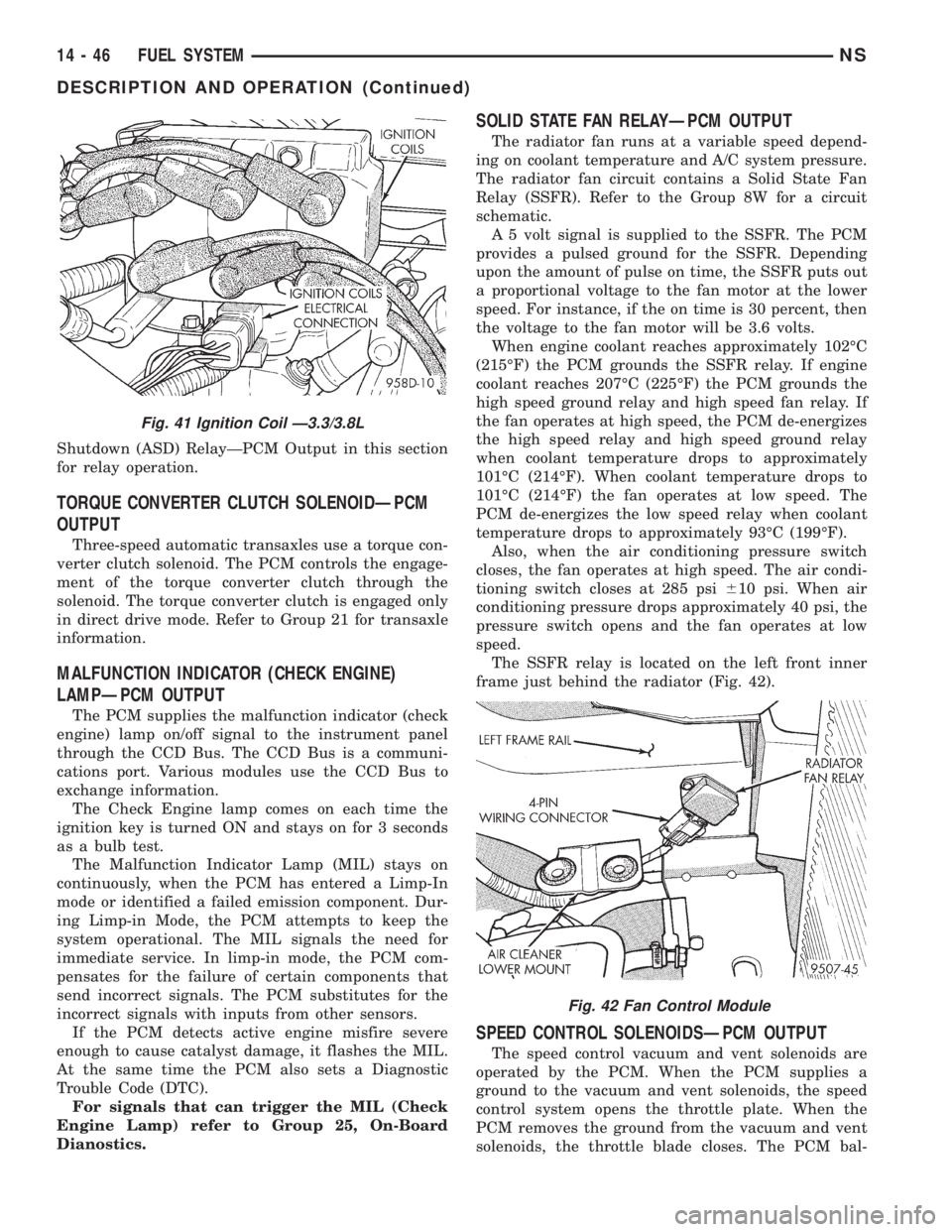
The SSFR relay is located on the left front inner
frame just behind the radiator (Fig. 42).
SPEED CONTROL SOLENOIDSÐPCM OUTPUT
The speed control vacuum and vent solenoids are
operated by the PCM. When the PCM supplies a
ground to the vacuum and vent solenoids, the speed
control system opens the throttle plate. When the
PCM removes the ground from the vacuum and vent
solenoids, the throttle blade closes. The PCM bal-
Fig. 41 Ignition Coil Ð3.3/3.8L
Fig. 42 Fan Control Module
14 - 46 FUEL SYSTEMNS
DESCRIPTION AND OPERATION (Continued)
Page 1416 of 1938
The speed sensor generates 8 pulses per sensor
revolution. These signals, in conjunction with a
closed throttle signal from the throttle position sen-
sor, indicate a closed throttle deceleration to the
PCM. When the vehicle is stopped at idle, a closed
throttle signal is received by the PCM (but a speed
sensor signal is not received).
In addition to determining distance and vehicle
speed, the output from the sensor is used to control
speed control operation.
SPEED CONTROLÐPCM INPUTS
The speed control system provides five separate
inputs to the PCM; On/Off, Set, Resume/Accel, Cancel,
and Decel.. The On/Off input informs the PCM that
the speed control system has been activated. The Set
input informs the PCM that a fixed vehicle speed has
been selected. The Resume input indicates to the PCM
that the previous fixed speed is requested.
Speed control operation will start at 50 km/h±142
km/h (35±85 mph). The upper range of operation is
not restricted by vehicle speed. Inputs that affect
speed control operation are vehicle speed sensor and
throttle position sensor.
Refer to Group 8H for further speed control infor-
mation.
DIESEL PCM RELAYÐPCM INPUT
A 12 volt signal at this input indicates to the PCM
that the Diesel relay has been activated. The Diesel
relay is located in the PDC. The PDC is located next
to the battery in the engine compartment. For the
location of the relay within the PDC, refer to label on
PDC cover.
This input is used only to sense that the Diesel
relay is energized. If the PCM does not see 12 volts +
at this input when the Diesel relay should be acti-
vated, it will set a Diagnostic Trouble Code (DTC).
FIVE VOLT POWERÐPCM OUTPUT
This circuit supplies approximately 5 volts to
power the Accelerator Pedal Postion Sensor, Mass Air
Flow Sensor, and A/C Pressure Sensor.
ENGINE COOLANT GAUGEÐPCM OUTPUT
Refer to the Instrument Panel and Gauges group
for additional information.
ENGINE OIL PRESSURE GAUGEÐPCM OUTPUT
Refer to the Instrument Panel and Gauges group
for additional information.
GLOW PLUG LAMPÐPCM OUTPUT
The Glow Plug lamp (malfunction indicator lamp)
illuminates on the message center each time the igni-
tion (key) switch is turned on. It will stay on for
about two seconds as a bulb test.If the PCM receives an incorrect signal, or no sig-
nal from certain sensors or components, the lamp
BLINKS. This is a warning that the PCM has
recorded a system or sensor malfunction. It signals
an immediate need for service. There are only 5
HARD faults that can turn on this lamp to make it
blink.
SPEED CONTROLÐPCM OUTPUTS
These two circuits control the fuel quantity actua-
tor to regulate vehicle speed. Refer to Group 8H for
Speed Control information.
AIR CONDITIONING RELAYÐPCM OUTPUT
This circuit controls a ground signal for operation
of the A/C clutch relay. Also refer to Air Conditioning
(A/C) ControlsÐPCM Input for additional informa-
tion.
The A/C relay is located in the Power Distribution
Center (PDC). The PDC is located next to the battery
in the engine compartment. For the location of the
relay within the PDC, refer to label on PDC cover.
FUEL TIMING SOLENOIDÐPCM OUTPUT
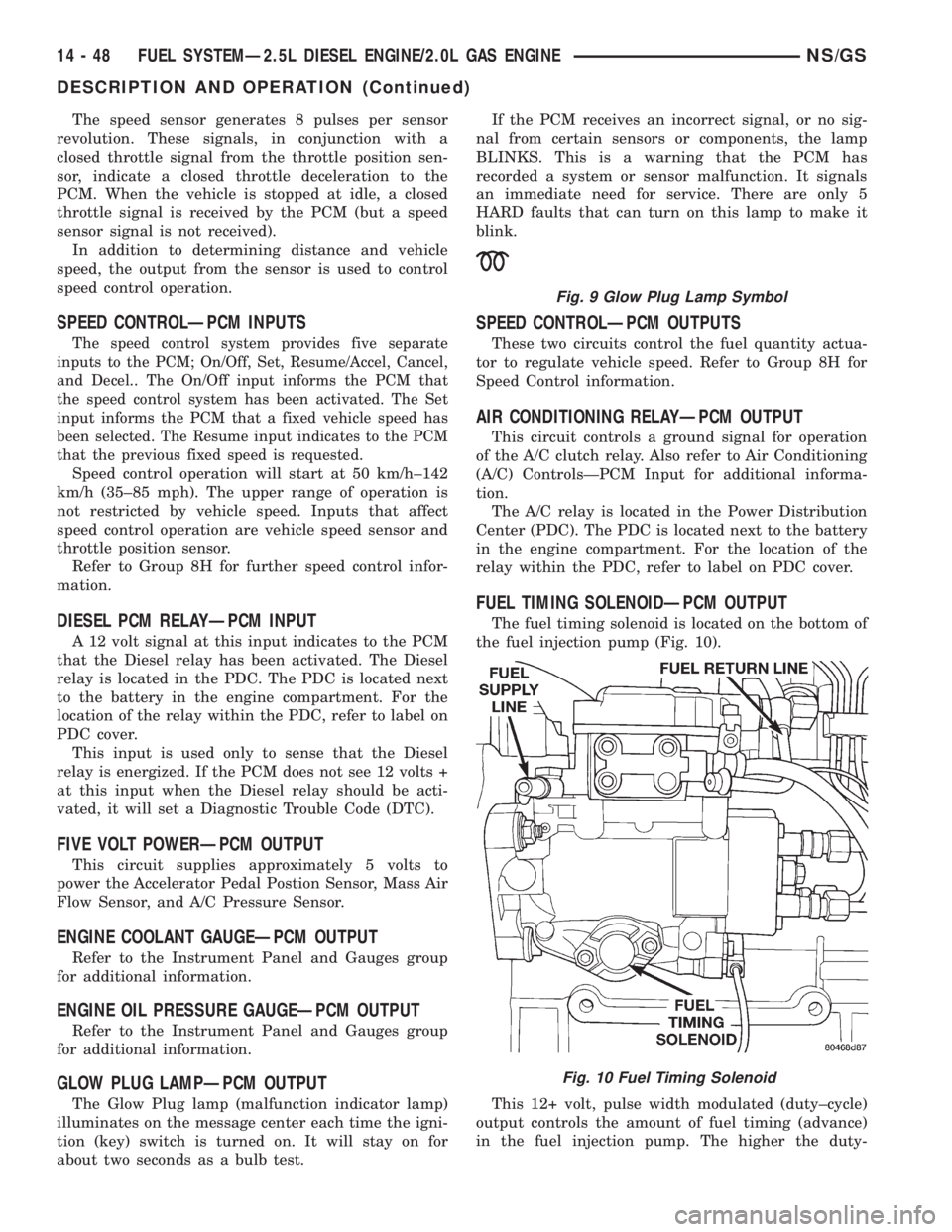
The fuel timing solenoid is located on the bottom of
the fuel injection pump (Fig. 10).
This 12+ volt, pulse width modulated (duty±cycle)
output controls the amount of fuel timing (advance)
in the fuel injection pump. The higher the duty-
Fig. 9 Glow Plug Lamp Symbol
Fig. 10 Fuel Timing Solenoid
14 - 48 FUEL SYSTEMÐ2.5L DIESEL ENGINE/2.0L GAS ENGINENS/GS
DESCRIPTION AND OPERATION (Continued)