1996 CHRYSLER VOYAGER oil change
[x] Cancel search: oil changePage 549 of 1938

SEAT BELT CHIME
The seat belt chime will sound for 4 to 8 seconds,
when the ignition is turned on and the driver's seat
belt is not buckled (seat belt switch is closed to
ground). This is a reminder to the driver to buckle
the seat belt. The seat belt lamp is controlled by the
mechanical instrument cluster. The cluster will also
illuminate the seat belt warning lamp for 6 seconds.
Buckling the driver's seat belt before the time out
has expired will cause the chime to stop immediately.
Chime rate: 38 to 62 chimes per minute.
To test the seat belt warning system, the ignition
switch must be in the OFF position for 1 minute
before starting the test. Turn the ignition switch to
the on position with the driver's seat belt not buck-
led. The seat belt warning lamp should light and the
chime should sound 4 to 8 seconds.
SEAT BELT LAMP
The seat belt lamp in the instrument cluster sig-
nals the vehicle passengers to fasten their seat belts.
The seat belt lamp is illuminated directly by the
instrument cluster for 6 seconds after the instrument
cluster receives the message from the Body Control
Module. The seat belt lamp is therefore illuminated
for 6 seconds whenever the ignition switch is moved
to run/start position.
(1) While ignition is off, the seat belt lamp will not
be illuminated.
(2) The ignition power feed status will be updated
every 250 milliseconds or on change.
(3) This lamp will be checked by the instrument
cluster for 6 seconds with every run/start cycle of the
ignition switch.
TURN SIGNAL ON CHIME
The turn signal on chime will warn the driver that
the turn signals have been left on. When the Body
Control Module receives a turn signal input for 1.6
km (1.0 miles), vehicle speed is greater than 24 km/h
(15 mph), the chime will sound continuously until the
turn signal is turned OFF. If vehicle speed drops
below 24 km/h (15 mph) prior to the warning being
activated, the accumulated distance traveled will be
reset. The turn signal chime is not activated whenthe emergency flashers are turned on. This feature
can also be disabled in EEPROM. Chime rate: 38 to
62 chimes per minute.
For the turn signal warning system to operate:
²Must have input from either the right or left
turn signal lamps. Creates a voltage change between
0 and battery voltage.
²The vehicle speed sensor sends a message to the
Powertrain Control Module that vehicle has exceeded
24 km/h (15 mph) for 1.6 km (1.0 miles).
²When the above two conditions are met, the
chime will sound. The chime will stop when no fur-
ther voltage change is detected.
²If hazard warning signals are pulsing, no chime
will sound.
²If speed drops below 24 km/h (15 mph) before
the warning is issued, the warning will not be issued
and the distance counter will be reset.
²If turn signal lamps are not working properly,
the chime will not sound.
²When using the scan tool, refer to the proper
Body Diagnostic Manual for the procedure.
WARNING LAMP ANNOUNCEMENT CHIME
The warning lamp announcement chime will warn
the driver to scan the instrument cluster to observe
which warning lamp is illuminated. Whenever the
volts, low fuel, low washer fluid, coolant level (gas/
diesel), low coolant level, engine temperature high
(diesel only), door ajar or gate ajar lamps are first
illuminated, the chime will sound one tone. The door/
liftgate ajar warning lamp announcement chime
sounds only if the vehicle speed is above 2 m.p.h.
Two seconds after ignition switch is turned ON or
until the seat belt warning chime ends, all warning
announcement chimes will be consolidated into one
warning announcement. This will occur 2 seconds
after the seat belt warning chime ends. If a warning
announcement should occur while another warning
chime in progress (turn signal, low oil pressure or
high speed warnings), no additional chimes will
sound after the chime in progress ends. All associ-
ated lamps will be illuminated, and the active chime
will be the warning announcement.
NS/GSCHIME WARNING/REMINDER SYSTEM 8U - 3
DIAGNOSIS AND TESTING (Continued)
Page 1051 of 1938
ENGINE
CONTENTS
page page
2.4L ENGINE............................ 14
3.0L ENGINE............................ 61
3.3/3.8L ENGINE........................ 93ENGINE DIAGNOSIS....................... 7
STANDARD SERVICE PROCEDURES.......... 1
STANDARD SERVICE PROCEDURES
INDEX
page page
GENERAL INFORMATION
CRANKSHAFT SPROCKET BOLT ACCESS
PLUG................................ 2
ENGINE CORE PLUGS.................... 2
ENGINE OIL SERVICE..................... 5
ENGINE OIL............................. 5
ENGINE PERFORMANCE.................. 2FORM-IN-PLACE GASKETS................. 1
HONING CYLINDER BORES................ 3
HYDROSTATIC LOCKED ENGINE............ 5
MEASURING MAIN BEARING AND
CONNECTING ROD BEARING
CLEARANCES......................... 3
REPAIR OF DAMAGED OR WORN THREADS . . . 4
GENERAL INFORMATION
FORM-IN-PLACE GASKETS
There are numerous places where form-in-place
gaskets are used on the engine. Care must be taken
when applying form-in-place gaskets.Do not use
form-in-place gasket material unless specified.
Bead size, continuity, and location are of great impor-
tance. Too thin a bead can result in leakage while too
much can result in spill-over, a continuous bead of
the proper width is essential to obtain a leak-free
joint.
Two types of form-in-place gasket materials are
used in the engine.MopartSilicone Rubber Adhe-
sive Sealant andMopartGasket Maker, (anaerobic)
each have different properties and cannot be used
interchangeably.
CAUTION: Silicone sealer and anaerobic sealers
each will inhibit the cure of the other and care
should be taken to keep usages separated as much
as possible.
MOPARTSILICONE RUBBER ADHESIVE
SEALANT
MopartSilicone Rubber Adhesive Sealant or
equivalent, normally black in color, is available in
three ounce tubes. Moisture in the air causes the
MopartSilicone Rubber Adhesive Sealant material
to cure. This material is normally used on flexible
metal flanges. It has a shelf life of one year and will
not properly cure if over age. Always inspect the
package for the expiration date before use.
MOPARTGASKET MAKER
MopartGasket Maker is an anaerobic type gasket
material normally red in color. The material cures in
the absence of air when squeezed between two metal-
lic surfaces. It will not cure if left in the uncovered
tube. It is normally red in color. The anaerobic mate-
rial is for use between two machined surfaces. Do not
use on flexible metal flanges.
MOPARTTORQUE CURE GASKET MAKER
MopartTorque Cure Gasket Maker is a unique
anaerobic type gasket material to be usedONLY
between the bedplate and engine block. The material
cures in the absence of air when torqued between
two metallic surfaces. It will not cure if left in the
uncovered tube. This anaerobic material is specially
NSENGINE 9 - 1
Page 1056 of 1938
API SERVICE GRADE CERTIFIED
Use an engine oil that is API Service Grade Certi-
fied. MOPARtprovides engine oils that conforms to
this service grade.
SAE VISCOSITY
An SAE viscosity grade is used to specify the vis-
cosity of engine oil. Use only, engine oils with multi-
ple viscosities such as 5W-30 or 10W-30. These are
specified with a dual SAE viscosity grade which indi-
cates the cold-to-hot temperature viscosity range.
Select an engine oil that is best suited to your par-
ticular temperature range and variation (Fig. 5).
ENERGY CONSERVING OIL
An Energy Conserving type oil is recommended for
gasoline engines. They are designated as either
ENERGY CONSERVING or ENERGY CONSERV-
ING II.
CONTAINER IDENTIFICATION
Standard engine oil identification notations have
been adopted to aid in the proper selection of engine
oil. The identifying notations are located on the label
of engine oil plastic bottles and the top of engine oil
cans (Fig. 6).
ENGINE OIL CHANGE
Change engine oil at mileage and time intervals
described in the Maintenance Schedule.
TO CHANGE ENGINE OIL
Run engine until achieving normal operating tem-
perature.
(1) Position the vehicle on a level surface and turn
engine off.
(2) Hoist and support vehicle on safety stands.
Refer to Hoisting and Jacking Recommendations.
(3) Remove oil fill cap.
(4) Place a suitable drain pan under crankcase
drain.
(5) Remove drain plug from crankcase and allow
oil to drain into pan. Inspect drain plug threads for
stretching or other damage. Replace drain plug and
gasket if damaged.
(6) Install drain plug in crankcase.
(7) Lower vehicle and fill crankcase with specified
type and amount of engine oil described in this sec-
tion.
(8) Install oil fill cap.
(9) Start engine and inspect for leaks.
(10) Stop engine and inspect oil level.
Fig. 5 Temperature/Engine Oil Viscosity
Fig. 6 Engine Oil Container Standard Notations
9 - 6 ENGINENS
GENERAL INFORMATION (Continued)
Page 1057 of 1938
ENGINE DIAGNOSIS
INDEX
page page
DIAGNOSIS AND TESTING
CYLINDER COMBUSTION
PRESSURE LEAKAGE TEST.............. 8
CYLINDER COMPRESSION PRESSURE TEST . . 7
ENGINE DIAGNOSISÐMECHANICAL......... 12
ENGINE DIAGNOSISÐPERFORMANCE...... 10GENERAL INFORMATION.................. 7
INSPECTION
(ENGINE OIL LEAKS IN GENERAL)......... 8
INTAKE MANIFOLD LEAKAGE DIAGNOSIS..... 7
LASH ADJUSTER (TAPPET)
NOISE DIAGNOSIS...................... 8
DIAGNOSIS AND TESTING
GENERAL INFORMATION
Engine diagnosis is helpful in determining the
causes of malfunctions.
These malfunctions may be classified as either
mechanical (e.g., a strange noise), or performance
(e.g., engine idles rough and stalls).
Refer to the Service DiagnosisÐMechanical Chart
and the Service DiagnosisÐPerformance Chart, for
possible causes and corrections of malfunctions. Refer
to Group 14, Fuel System, for the fuel system diag-
nosis.
Additional tests and diagnostic procedures may be
necessary for specific engine malfunctions that can-
not be isolated with the Service Diagnosis charts.
Information concerning additional tests and diagno-
sis is provided within the following:
²Cylinder Compression Pressure Test
²Cylinder Combustion Pressure Leakage Test
²Engine Cylinder Head Gasket Failure Diagnosis
²Intake Manifold Leakage Diagnosis
INTAKE MANIFOLD LEAKAGE DIAGNOSIS
An intake manifold air leak is characterized by
lower than normal manifold vacuum. Also, one or
more cylinders may not be functioning.
WARNING: USE EXTREME CAUTION WHEN THE
ENGINE IS OPERATING. DO NOT STAND IN A
DIRECT LINE WITH THE FAN. DO NOT PUT YOUR
HANDS NEAR THE PULLEYS, BELTS OR THE FAN.
DO NOT WEAR LOOSE CLOTHING.
(1) Start the engine.
(2) Spray a small stream of water (Spray Bottle) at
the suspected leak area.
(3) If a change in RPM'S, the area of the suspected
leak has been found.
(4) Repair as required.
CYLINDER COMPRESSION PRESSURE TEST
The results of a cylinder compression pressure test
can be utilized to diagnose several engine malfunc-
tions.
Ensure the battery is completely charged and the
engine starter motor is in good operating condition.
Otherwise the indicated compression pressures may
not be valid for diagnosis purposes.
(1) Check engine oil level and add oil if necessary.
(2) Drive the vehicle until engine reaches normal
operating temperature. Select a route free from traf-
fic and other forms of congestion, observe all traffic
laws, and accelerate through the gears several times
briskly.
(3) Remove all spark plugs from engine. As spark
plugs are being removed, check electrodes for abnor-
mal firing indicators fouled, hot, oily, etc. Record cyl-
inder number of spark plug for future reference.
(4) Disconnect coil wire from distributor and
secure to good ground to prevent a spark from start-
ing a fire (Conventional Ignition System). For Direct
Ignition System DIS disconnect the coil connector.
(5) Be sure throttle blade is fully open during the
compression check.
(6) Insert compression gage adaptor into the #1
spark plug hole in cylinder head. Crank engine until
maximum pressure is reached on gage. Record this
pressure as #1 cylinder pressure.
(7) Repeat the previous step for all remaining cyl-
inders.
(8) Compression should not be less than (689kPa)
100 psi and not vary more than 25 percent from cyl-
inder to cylinder.
(9) If one or more cylinders have abnormally low
compression pressures, repeat the compression test.
(10) If the same cylinder or cylinders repeat an
abnormally low reading on the second compression
test, it could indicate the existence of a problem in
the cylinder in question.The recommended com-
pression pressures are to be used only as a
guide to diagnosing engine problems. An engine
should not be disassembled to determine the
NSENGINE 9 - 7
Page 1058 of 1938
cause of low compression unless some malfunc-
tion is present.
(11) Clean or replace spark plugs as necessary
and adjust gap as specified in Group 8, Electrical.
Tighten to specifications.
(12) Test resistance of spark plug cables. Refer to
Group 8, Electrical Ignition System Secondary Cir-
cuit Inspection.
(13) Test coil output voltage, primary and second-
ary resistance. Replace parts as necessary. Refer to
Group 8, Electrical Ignition System.
(14) Check fuel pump pressure at idle and differ-
ent RPM ranges. Refer to Group 14, Fuel System for
Specifications.
(15) The air filter elements should be replaced as
specified in Group 0, Lubrication and Maintenance,.
(16) Inspect crankcase ventilation system as out
lined in Group 0, Lubrication and Maintenance. For
emission controls see Group 25, Emission Controls
for service procedures.
(17) Inspect and adjust accessory belt drives refer-
ring to Group 7, Cooling System, Accessory Drive
Belts for proper adjustments.
(18) Road test vehicle as a final test.
CYLINDER COMBUSTION PRESSURE LEAKAGE
TEST
The combustion pressure leakage test provides an
accurate means for determining engine condition.
Combustion pressure leakage testing will detect:
²Exhaust and intake valve leaks (improper seat-
ing).
²Leaks between adjacent cylinders or into water
jacket.
²Any causes for combustion/compression pressure
loss.
WARNING: DO NOT REMOVE THE RADIATOR CAP
WITH THE SYSTEM HOT AND UNDER PRESSURE
BECAUSE SERIOUS BURNS FROM COOLANT CAN
OCCUR.
Check the coolant level and fill as required. DO
NOT install the radiator cap.
Start and operate the engine until it attains nor-
mal operating temperature, then turn the engine
OFF.
Clean spark plug recesses with compressed air.
Remove the spark plugs.
Remove the oil filler cap.
Remove the air cleaner.
Calibrate the tester according to the manufactur-
er's instructions. The shop air source for testing
should maintain 483 kPa (70 psi) minimum, 1 379
kPa (200 psi) maximum and 552 kPa (80 psi) recom-
mended.Perform the test procedures on each cylinder
according to the tester manufacturer's instructions.
While testing, listen for pressurized air escaping
through the throttle body, tailpipe and oil filler cap
opening. Check for bubbles in the radiator coolant.
All gauge pressure indications should be equal,
with no more than 25% leakage.
FOR EXAMPLE:At 552 kPa (80 psi) input pres-
sure, a minimum of 414 kPa (60 psi) should be main-
tained in the cylinder.
LASH ADJUSTER (TAPPET) NOISE DIAGNOSIS
A tappet-like noise may be produced from several
items. Check the following items.
(1) Engine oil level too high or too low. This may
cause aerated oil to enter the adjusters and cause
them to be spongy.
(2) Insufficient running time after rebuilding cylin-
der head. Low speed running up to 1 hour may be
required.
(3) During this time, turn engine off and let set for
a few minutes before restarting. Repeat this several
times after engine has reached normal operating
temperature.
(4) Low oil pressure.
(5) The oil restrictor pressed into the vertical oil
passage to the cylinder head is plugged with debris.
(6) Air ingested into oil due to broken or cracked
oil pump pick up.
(7) Worn valve guides.
(8) Rocker arm ears contacting valve spring
retainer.
(9) Rocker arm loose, adjuster stuck or at maxi-
mum extension and still leaves lash in the system.
(10) Faulty lash adjuster.
a. Check lash adjusters for sponginess while
installed in cylinder head. Depress part of rocker
arm over adjuster. Normal adjusters should feel very
firm. Spongy adjusters can be bottomed out easily.
b. Remove suspected lash adjusters, and disassem-
bleDo not reuse retainer caps. Do not inter-
change parts and make sure that care and
cleanliness is exercised in the handling of parts.
c. Clean out dirt and varnish with solvent.
d. Reassemble with engine oil.
e. Check for sponginess.
f. If still spongy, replace with new adjuster.
INSPECTION (ENGINE OIL LEAKS IN GENERAL)
Begin with a through visual inspection of the
engine, particularly at the area of the suspected leak.
If an oil leak source is not readily identifiable, the
following steps should be followed:
(1) Do not clean or degrease the engine at this
time because some solvents may cause rubber to
swell, temporarily stopping the leak.
9 - 8 ENGINENS
DIAGNOSIS AND TESTING (Continued)
Page 1062 of 1938
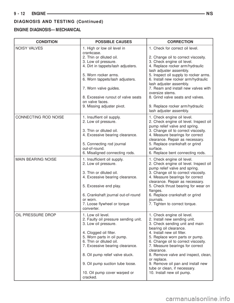
ENGINE DIAGNOSISÐMECHANICAL
CONDITION POSSIBLE CAUSES CORRECTION
NOISY VALVES 1. High or low oil level in
crankcase.1. Check for correct oil level.
2. Thin or diluted oil. 2. Change oil to correct viscosity.
3. Low oil pressure. 3. Check engine oil level.
4. Dirt in tappets/lash adjusters. 4. Replace rocker arm/hydraulic
lash adjuster assembly.
5. Worn rocker arms. 5. Inspect oil supply to rocker arms.
6. Worn tappets/lash adjusters. 6. Install new rocker arm/hydraulic
lash adjuster assembly.
7. Worn valve guides. 7. Ream and install new valves with
oversize stems.
8. Excessive runout of valve seats
on valve faces.8. Grind valve seats and valves.
9. Missing adjuster pivot. 9. Replace rocker arm/hydraulic
lash adjuster assembly.
CONNECTING ROD NOISE 1. Insuffient oil supply. 1. Check engine oil level.
2. Low oil pressure. 2. Check engine oil level. Inspect oil
pump relief valve and spring.
3. Thin or diluted oil. 3. Change oil to correct viscosity.
4. Excessive bearing clearance. 4. Measure bearings for correct
clearance. Repair as necessary.
5. Connecting rod journal
out-of-round.5. Replace crankshaft or grind
surface.
6. Misaligned connecting rods. 6. Replace bent connecting rods.
MAIN BEARING NOISE 1. Insufficient oil supply. 1. Check engine oil level.
2. Low oil pressure. 2. Check engine oil level. Inspect oil
pump relief valve and spring.
3. Thin or diluted oil. 3. Change oil to correct viscosity.
4. Excessive bearing clearance. 4. Measure bearings for correct
clearance. Repair as necessary.
5. Excessive end play. 5. Check thrust bearing for wear on
flanges.
6. Crankshaft journal out-of-round
or worn.6. Replace crankshaft or grind
journals.
7. Loose flywheel or torque
converter.7. Tighten to correct torque.
OIL PRESSURE DROP 1. Low oil level. 1. Check engine oil level.
2. Faulty oil pressure sending unit. 2. Install new sending unit.
3. Low oil pressure. 3. Check sending unit and main
bearing oil clearance.
4. Clogged oil filter. 4. Install new oil filter.
5. Worn parts in oil pump. 5. Replace worn parts or pump.
6. Thin or diluted oil. 6. Change oil to correct viscosity.
7. Excessive bearing clearance. 7. Measure bearings for correct
clearance.
8. Oil pump relief valve stuck. 8. Remove valve and inspect, clean,
or replace.
9. Oil pump suction tube loose. 9. Remove oil pan and install new
tube or clean, if necessary.
10. Oil pump cover warped or
cracked.10. Install new oil pump.
9 - 12 ENGINENS
DIAGNOSIS AND TESTING (Continued)
Page 1069 of 1938
scale provided on the package. Locate the band clos-
est to the same width. This band shows the amount
of clearance in thousandths of a millimeter. Differ-
ences in readings between the ends indicate the
amount of taper present. Record all readings taken.
Refer to Engine Specifications.Plastigage gener-
ally is accompanied by two scales. One scale is
in inches, the other is a metric scale.
(6) Plastigage is available in a variety of clearance
ranges. The 0.025-0.076 mm (.001-.003 in.) is usually
the most appropriate for checking engine bearing
proper specifications.
FITTING MAIN BEARINGS
Refer to the Engine General Information Section
for Measuring Main Bearings. For Crankshaft speci-
fications refer to Crankshaft Specification Chart.
CRANKSHAFT MAIN BEARINGS
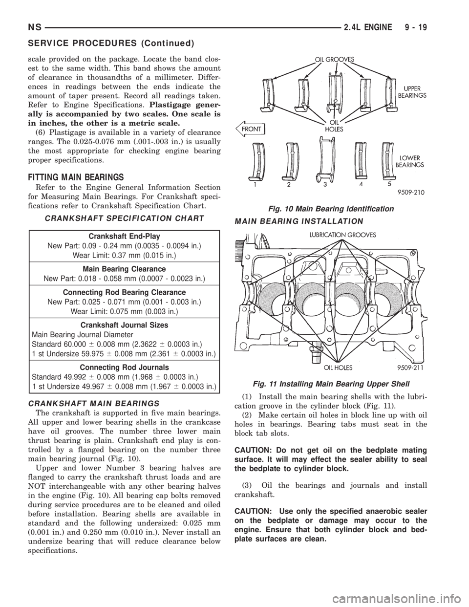
The crankshaft is supported in five main bearings.
All upper and lower bearing shells in the crankcase
have oil grooves. The number three lower main
thrust bearing is plain. Crankshaft end play is con-
trolled by a flanged bearing on the number three
main bearing journal (Fig. 10).
Upper and lower Number 3 bearing halves are
flanged to carry the crankshaft thrust loads and are
NOT interchangeable with any other bearing halves
in the engine (Fig. 10). All bearing cap bolts removed
during service procedures are to be cleaned and oiled
before installation. Bearing shells are available in
standard and the following undersized: 0.025 mm
(0.001 in.) and 0.250 mm (0.010 in.). Never install an
undersize bearing that will reduce clearance below
specifications.
MAIN BEARING INSTALLATION
(1) Install the main bearing shells with the lubri-
cation groove in the cylinder block (Fig. 11).
(2) Make certain oil holes in block line up with oil
holes in bearings. Bearing tabs must seat in the
block tab slots.
CAUTION: Do not get oil on the bedplate mating
surface. It will may effect the sealer ability to seal
the bedplate to cylinder block.
(3) Oil the bearings and journals and install
crankshaft.
CAUTION: Use only the specified anaerobic sealer
on the bedplate or damage may occur to the
engine. Ensure that both cylinder block and bed-
plate surfaces are clean.
CRANKSHAFT SPECIFICATION CHART
Crankshaft End-Play
New Part: 0.09 - 0.24 mm (0.0035 - 0.0094 in.)
Wear Limit: 0.37 mm (0.015 in.)
Main Bearing Clearance
New Part: 0.018 - 0.058 mm (0.0007 - 0.0023 in.)
Connecting Rod Bearing Clearance
New Part: 0.025 - 0.071 mm (0.001 - 0.003 in.)
Wear Limit: 0.075 mm (0.003 in.)
Crankshaft Journal Sizes
Main Bearing Journal Diameter
Standard 60.00060.008 mm (2.362260.0003 in.)
1 st Undersize 59.97560.008 mm (2.36160.0003 in.)
Connecting Rod Journals
Standard 49.99260.008 mm (1.96860.0003 in.)
1 st Undersize 49.96760.008 mm (1.96760.0003 in.)
Fig. 10 Main Bearing Identification
Fig. 11 Installing Main Bearing Upper Shell
NS2.4L ENGINE 9 - 19
SERVICE PROCEDURES (Continued)
Page 1078 of 1938
CYLINDER HEAD COVER
REMOVAL
(1) Remove upper intake manifold. Refer to Group
11, Exhaust System and Intake Manifold.
(2) Remove nuts attaching front and rear intake
manifold supports from cylinder head cover attaching
studs.
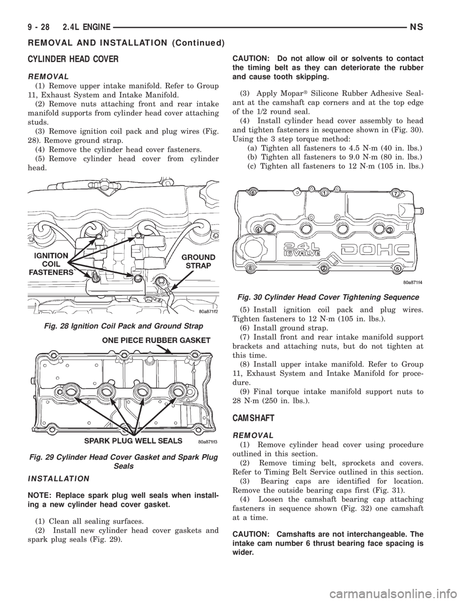
(3) Remove ignition coil pack and plug wires (Fig.
28). Remove ground strap.
(4) Remove the cylinder head cover fasteners.
(5) Remove cylinder head cover from cylinder
head.
INSTALLATION
NOTE: Replace spark plug well seals when install-
ing a new cylinder head cover gasket.
(1) Clean all sealing surfaces.
(2) Install new cylinder head cover gaskets and
spark plug seals (Fig. 29).CAUTION: Do not allow oil or solvents to contact
the timing belt as they can deteriorate the rubber
and cause tooth skipping.
(3) Apply MopartSilicone Rubber Adhesive Seal-
ant at the camshaft cap corners and at the top edge
of the 1/2 round seal.
(4) Install cylinder head cover assembly to head
and tighten fasteners in sequence shown in (Fig. 30).
Using the 3 step torque method:
(a) Tighten all fasteners to 4.5 N´m (40 in. lbs.)
(b) Tighten all fasteners to 9.0 N´m (80 in. lbs.)
(c) Tighten all fasteners to 12 N´m (105 in. lbs.)
(5) Install ignition coil pack and plug wires.
Tighten fasteners to 12 N´m (105 in. lbs.).
(6) Install ground strap.
(7) Install front and rear intake manifold support
brackets and attaching nuts, but do not tighten at
this time.
(8) Install upper intake manifold. Refer to Group
11, Exhaust System and Intake Manifold for proce-
dure.
(9) Final torque intake manifold support nuts to
28 N´m (250 in. lbs.).
CAMSHAFT
REMOVAL
(1) Remove cylinder head cover using procedure
outlined in this section.
(2) Remove timing belt, sprockets and covers.
Refer to Timing Belt Service outlined in this section.
(3) Bearing caps are identified for location.
Remove the outside bearing caps first (Fig. 31).
(4) Loosen the camshaft bearing cap attaching
fasteners in sequence shown (Fig. 32) one camshaft
at a time.
CAUTION: Camshafts are not interchangeable. The
intake cam number 6 thrust bearing face spacing is
wider.
Fig. 28 Ignition Coil Pack and Ground Strap
Fig. 29 Cylinder Head Cover Gasket and Spark Plug
Seals
Fig. 30 Cylinder Head Cover Tightening Sequence
9 - 28 2.4L ENGINENS
REMOVAL AND INSTALLATION (Continued)