1996 CHRYSLER VOYAGER heater
[x] Cancel search: heaterPage 241 of 1938

COOLING SYSTEM
CONTENTS
page page
GENERAL INFORMATION
COOLANT PRESSURE BOTTLE............ 1
COOLING SYSTEM Ð 2.0L GASOLINE...... 1
COOLING SYSTEM Ð 2.5L VM DIESEL..... 1
LOW COOLANT LEVEL SENSOR........... 1
RADIATOR............................ 2
DESCRIPTION AND OPERATION
AUTOMATIC BELT TENSIONER............ 6
BELT TENSION......................... 5
COOLANT PERFORMANCE............... 5
PRESSURE/VENT CAP................... 4
THERMOSTAT OPERATION............... 4
THERMOSTAT......................... 6
WATER PUMP......................... 3
SERVICE PROCEDURES
ADDING ADDITIONAL COOLANT........... 7
DRAINING COOLING SYSTEM............. 7
REFILLING COOLING SYSTEM............ 7
REMOVAL AND INSTALLATION
ENGINE THERMOSTATÐ 2.0L GASOLINE . . . 9GENERATOR/POWER STEERING BELT Ð 2.5L
VM DIESEL......................... 10
RADIATOR Ð 2.5L VM DIESEL........... 9
THERMOSTAT Ð 2.5L VM DIESEL......... 9
WATER PUMP BELT Ð 2.5L VM DIESEL . . . 10
WATER PUMP Ð 2.0L GASOLINE......... 7
WATER PUMP Ð 2.5L VM DIESEL........ 8
CLEANING AND INSPECTION
WATER PUMP........................ 10
ADJUSTMENTS
BELT TENSION CHART................. 11
BELT TENSION GAUGE METHOD......... 11
SPECIFICATIONS
COOLING SYSTEM CAPACITY............ 12
TORQUE CHART...................... 12
SPECIAL TOOLS
COOLING............................ 12
GENERAL INFORMATION
COOLING SYSTEM Ð 2.0L GASOLINE
The 2.0L gasoline engine cooling system consists of
an engine cooling module, thermostat, coolant, a
water pump to circulate the coolant. The engine cool-
ing module may consist of a radiator, electric fan
motors, fan, shroud, coolant reserve system, hoses,
clamps, air condition condenser.
²When the Engine is cold: The thermostat is
closed; the cooling system has no flow through the
radiator. The coolant flows through the engine,
heater system and bypass.
²When the Engine is warm: Thermostat is open;
the cooling system has flow through radiator, engine,
heater system and bypass.
COOLING SYSTEM Ð 2.5L VM DIESEL
The cooling system has a radiator, coolant, electric
fan motors, shroud, pressure cap, thermostat, coolant
pressure bottle, hoses, a water pump to circulate the
coolant, to complete the circuit. Coolant flow for the
VM diesel engine is shown in (Fig. 1).
COOLANT PRESSURE BOTTLE
2.5L VM DIESEL
This system works with the pressure cap to use
thermal expansion and contraction of the coolant to
keep the coolant free of trapped air. It provides some
reserve coolant to cover minor leaks and evaporation
or boiling losses. The coolant pressure bottle location
for 2.5L diesel is above the cylinder head cover (Fig.
2).
LOW COOLANT LEVEL SENSOR
The low coolant level sensor checks for low coolant
level in the coolant tank. A signal will be sent from
this sensor to the Body Control Module (BCM). When
the BCM determines low coolant level for 30 contin-
uous seconds, the instrument panel mounted low
coolant level warning lamp will be illuminated. The
sensor is located on the front side of the coolant tank
(Fig. 4). For information, refer to Group 8E, Instru-
ment Panel and Gauges.
If this lamp is illuminated, it indicates the need to
fill the coolant tank and check for leaks.
NS/GSCOOLING SYSTEM 7 - 1
Page 246 of 1938
Initial belt adjustment is done with a adjustable
tensioner pulley. After the initial adjustment is per-
formed, an automatic belt tensioner is used to main-
tain correct belt tension at all times. Do not attempt
to check belt tension with a belt tension gauge on
vehicles equipped with an automatic belt tensioner.
Refer to Automatic Belt Tensioner in this group.
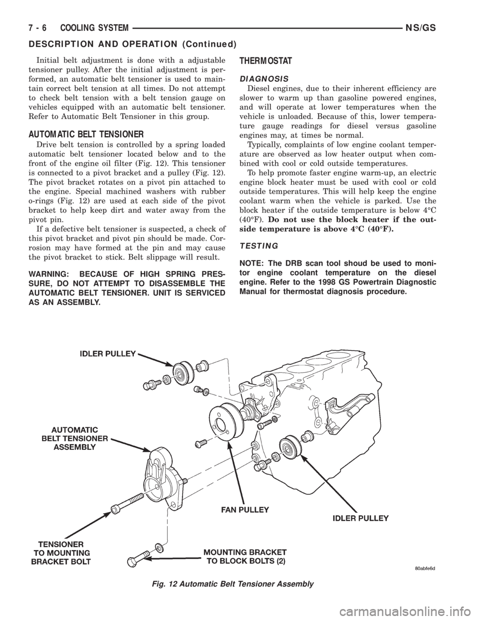
AUTOMATIC BELT TENSIONER
Drive belt tension is controlled by a spring loaded
automatic belt tensioner located below and to the
front of the engine oil filter (Fig. 12). This tensioner
is connected to a pivot bracket and a pulley (Fig. 12).
The pivot bracket rotates on a pivot pin attached to
the engine. Special machined washers with rubber
o-rings (Fig. 12) are used at each side of the pivot
bracket to help keep dirt and water away from the
pivot pin.
If a defective belt tensioner is suspected, a check of
this pivot bracket and pivot pin should be made. Cor-
rosion may have formed at the pin and may cause
the pivot bracket to stick. Belt slippage will result.
WARNING: BECAUSE OF HIGH SPRING PRES-
SURE, DO NOT ATTEMPT TO DISASSEMBLE THE
AUTOMATIC BELT TENSIONER. UNIT IS SERVICED
AS AN ASSEMBLY.
THERMOSTAT
DIAGNOSIS
Diesel engines, due to their inherent efficiency are
slower to warm up than gasoline powered engines,
and will operate at lower temperatures when the
vehicle is unloaded. Because of this, lower tempera-
ture gauge readings for diesel versus gasoline
engines may, at times be normal.
Typically, complaints of low engine coolant temper-
ature are observed as low heater output when com-
bined with cool or cold outside temperatures.
To help promote faster engine warm-up, an electric
engine block heater must be used with cool or cold
outside temperatures. This will help keep the engine
coolant warm when the vehicle is parked. Use the
block heater if the outside temperature is below 4ÉC
(40ÉF).Do not use the block heater if the out-
side temperature is above 4ÉC (40ÉF).
TESTING
NOTE: The DRB scan tool shoud be used to moni-
tor engine coolant temperature on the diesel
engine. Refer to the 1998 GS Powertrain Diagnostic
Manual for thermostat diagnosis procedure.
Fig. 12 Automatic Belt Tensioner Assembly
7 - 6 COOLING SYSTEMNS/GS
DESCRIPTION AND OPERATION (Continued)
Page 247 of 1938

SERVICE PROCEDURES
ADDING ADDITIONAL COOLANT
2.5L VM DIESEL
Do not remove coolant bottle pressure cap when
the engine is hot. Remove pressure cap and fill cool-
ant bottle between Min and Max lines inside filler
neck. Use only 50/50 mix of ethylene glycol type anti-
freeze and water (Fig. 13). Squeezing radiator hoses
may help purge air from the cooling system.
DRAINING COOLING SYSTEM
2.0L GASOLINE
To drain cooling system move temperature selector
for heater to full heat with engine running.Without
removing radiator pressure cap and with sys-
tem not under pressure,Shut engine off and open
draincock. The coolant reserve tank should empty
first, then remove radiator pressure cap and let the
radiator drain (if not, see Testing Cooling System for
leaks).
2.5L VM DIESEL
The cooling system does not have a radiator
mounted pressure cap. Instead the pressure cap is
mounted on the coolant pressure bottle (Fig. 14).
(1) Shut off engine.
(2) Remove radiator pressure cap.
(3) Open draincock and allow coolant to drain.
REFILLING COOLING SYSTEM
2.0L GASOLINE
Refer to the gasoline engine cooling system infor-
mation in this manual. Cooling system capacity is 6.0
liters (6.34 qts.) which includes the heater and cool-
ant recovery tank.
2.5L VM DIESEL
First clean system to remove old glycol, see Cooling
System Cleaning.
(1) Disconnect upper radiator hose at thermostat
housing.
(2) Remove pressure cap from coolant expansion
tank.
(3) Fill cooling system through upper radiator hose
until coolant starts to leak out at the thermostat
housing. Reconnect hose and re-install clamp.
(4) Fill expansion tank to top of bottle. Run engine
at idle without pressure cap installed for 5 minutes.
Squeeze upper radiator hose several times.
(5) Shut off engine. Top off coolant and install
pressure cap.
(6) Inspect system for leaks.
REMOVAL AND INSTALLATION
WATER PUMP Ð 2.0L GASOLINE
REMOVAL
(1) Remove accessory drive belts and power steer-
ing pump.
(2) Drain cooling system.
Fig. 13 Coolant Pressure BottleÐ2.5L VM Diesel
Fig. 14 Pressure Cap and BottleÐVM Diesel
NS/GSCOOLING SYSTEM 7 - 7
Page 252 of 1938
SPECIFICATIONS
COOLING SYSTEM CAPACITY
TORQUE CHART
SPECIAL TOOLS
COOLING
2.0L Gasoline *10.6 liters (11 qts.)
2.5L VM Diesel *10.0 liters (10.6 qts.)
*Includes Heater and Coolant recovery/pressure Tank.
COMPONENT 2.0L
GASOLINE2.5L VM
Thermostat
Cover Bolts105 in-lbs 10.8 N´m (96 in.
lbs.)
Water Pump
Mounting Bolts12 N´m (105 in.
lbs.)22.6 N´m (204
in. lbs.)
Water Pump
Pulley BoltsN/A 27.5 N´m (240
in. lbs.)
Upper Radiator
Mounting
Bracket Bolts12 N´m (105 in.
lbs.)12 N´m (105 in.
lbs.)
Turbocharger
Oil Supply LineN/A 24.5 N´m (215
in. lbs.)
Turbocharger
Oil Return LineN/A 10.8 N´m (96 in.
lbs.)
Water Pump
Housing NutsN/A 9.5 N´m (84 in.
lbs.)
Water Manifold
BoltsN/A 11.2 N´m (96 in.
lbs.)
Coolant Bottle
Bolts2.0 N´m (18 in.
lbs.)10.8 N´m (96 in.
lbs.)
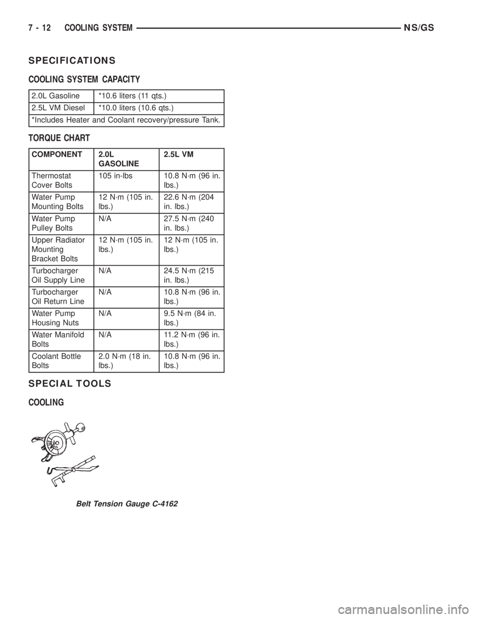
Belt Tension Gauge C-4162
7 - 12 COOLING SYSTEMNS/GS
Page 290 of 1938

CHARGING SYSTEM RESISTANCE TESTS
These tests will show the amount of voltage drop
across the generator output wire from the generator
output (B+) terminal to the battery positive post.
They will also show the amount of voltage drop from
the ground (-) terminal on the generator or case
ground (Fig. 1) to the battery negative post.
A voltmeter with a 0±18 volt DC scale should be
used for these tests. By repositioning the voltmeter
test leads, the point of high resistance (voltage drop)
can easily be found.
PREPARATION
(1) Before starting test, make sure battery is in
good condition and is fully-charged. See Group 8A,
Battery for more information.
(2) Check condition of battery cables at battery.
Clean if necessary.
(3) Start the engine and allow it to reach normal
operating temperature.
(4) Shut engine off.
(5) Connect an engine tachometer.
(6) Fully engage the parking brake.
TEST
(1) Start engine.
(2) Place heater blower in high position.
(3) Turn on headlamps and place in high-beam
position.
(4) Turn rear window defogger on.
(5) Bring engine speed up to 2400 rpm and hold.
(6) Testing (+ positive) circuitry:
(a) Touch the negative lead of voltmeter directly
to battery positivePOST(Fig. 2).
(b) Touch the positive lead of voltmeter to the
B+ output terminal stud on the generator (not the
terminal mounting nut). Voltage should be no
higher than 0.6 volts. If voltage is higher than 0.6
volts, touch test lead to terminal mounting stud
nut and then to the wiring connector. If voltage is
now below 0.6 volts, look for dirty, loose or poor
connection at this point. Also check condition of the
generator output wire-to-battery bullet connector.
Refer to Group 8, Wiring for connector location. A
voltage drop test may be performed at each (-
ground) connection in this circuit to locate the
excessive resistance.
(7) Testing (- ground) circuitry:
(a) Touch the positive lead of voltmeter directly
to battery negativePOST.
(b) Touch the negative lead of voltmeter to the
generator case. Voltage should be no higher than
0.3 volts. If voltage is higher than 0.3 volts, touch
test lead to generator case and then to the engine
block. If voltage is now below 0.3 volts, look for
dirty, loose or poor connection at this point. A volt-
age drop test may be performed at each connectionin this circuit to locate the excessive resistance.
This test can also be performed between the gener-
ator case and the engine. If test voltage is higher
than 0.3 volts, check for corrosion at generator
mounting points or loose generator mounting.
CURRENT OUTPUT TEST
The current output test will determine if the
charging system can deliver its minimum test cur-
rent (amperage) output. Refer to the Specifications
section at the end of this group for minimum test
current (amperage) requirements.
The first part of this test will determine the com-
bined amperage output of both the generator and the
Electronic Voltage Regulator (EVR) circuitry.
PREPARATION
(1) Determine if any Diagnostic Trouble Codes
(DTC) exist. To determine a DTC, refer to On-Board
Diagnostics in this group. For repair, refer to the
appropriate Powertrain Diagnostic Procedures man-
ual.
(2) Before starting test, make sure battery is in
good condition and is fully-charged. See Group 8A,
Battery for more information.
(3) Check condition of battery cables at battery.
Clean if necessary.
(4) Perform the Voltage Drop Test. This will
ensure clean and tight generator/battery electrical
connections.
(5) Be sure the generator drive belt is properly
tensioned. Refer to Group 7, Cooling System for
information.
(6) A volt/amp tester equipped with both a battery
load control (carbon pile rheostat) and an inductive-
type pickup clamp (ammeter probe) will be used for
this test. Refer to operating instructions supplied
with tester. When using a tester equipped with an
inductive-type clamp, removal of wiring at the gener-
ator will not be necessary.
(7) Start the engine and allow it to reach operating
temperature.
(8) Shut engine off.
(9) Turn off all electrical accessories and all vehicle
lighting.
(10) Connect the volt/amp tester leads to the bat-
tery. Be sure the carbon pile rheostat control is in the
OPEN or OFF position before connecting leads. See
Load Test in Group 8A, Battery for more information.
Also refer to the operating instructions supplied with
test equipment.
(11) Connect the inductive clamp (ammeter probe).
Refer to the operating instructions supplied with test
equipment.
(12) If volt/amp tester is not equipped with an
engine tachometer, connect a separate tachometer to
the engine.
8C - 4 CHARGING SYSTEMNS
DIAGNOSIS AND TESTING (Continued)
Page 302 of 1938

Clean Spark Plug cables with a cloth moistened
with a non-flammable solvent. Wipe the cables dry.
Check for brittle or cracked insulation.
SPARK PLUG CABLESÐ3.3/3.8L
The spark plug cables and spark plug boots are
made from high temperature silicone materials. The
spark plug boots utilize metal heat shields for ther-
mal protection from the exhaust manifold. The heat
shields slide over the spark plug boots. The notches
on the heat shields ensure the spark plug boot and
shield twist together during spark plug boot removal.
They also identify proper heat shield installation on
the boot for service.Refer to 3.3/3.8L Spark Plug
Cable removal and installation.All spark plug
cable leads are properly identified with cylinder num-
bers. The inside of the spark plug boot is coated with
a special high temperature silicone grease for greater
sealing and to minimize boot bonding to the spark
plug insulator. The convoluted tubing on the rear
plug cables are made of a high temperature plastic
material. Under normal driving conditions, the spark
plug cables have a recommended service life of a
100,000 miles. The spark plugs have a recommended
service life of 75,000 miles for severe driving condi-
tions per schedule B in this manual.
The spark plug heat shield can be reused if an
ignition cable is replaced due to failure. Never reuse
heat shield's that have heat shield anti-twist, side or
spark plug attachment tabs bent or missing. Ensure
that the heat shield is properly attached to the spark
plug to avoid RFI problems. The bottom of the spark
plug heat shield must make contact with the spark
plug hex.
The front ignition cables must not make contact
with the oil dip stick tube and #5 cable must not
touch the coil mounting bolt to avoid abrasion/dielec-
tric failures.
IGNITION COIL
WARNING: THE DIRECT IGNITION SYSTEM GEN-
ERATES APPROXIMATELY 40,000 VOLTS. PER-
SONAL INJURY COULD RESULT FROM CONTACT
WITH THIS SYSTEM.
The ignition coil assembly consists of 3 indepen-
dent coils molded together (Fig. 4). The coil assembly
is mounted on the intake manifold. Spark plug cables
route to each cylinder from the coil. The coil fires two
spark plugs every power stroke. One plug is the cyl-
inder under compression, the other cylinder fires on
the exhaust stroke. The Powertrain Control Module
(PCM) determines which of the coils to charge and
fire at the correct time.
Coil 1 fires cylinders 1 and 4, coil 2 fires cylinders
2 and 5, coil 3 fires cylinders 3 and 6.The Auto Shutdown (ASD) relay provides battery
voltage to the ignition coil. The PCM provides a
ground contact (circuit) for energizing the coil. When
the PCM breaks the contact, the energy in the coil
primary transfers to the secondary causing the
spark. The PCM will de-energize the ASD relay if it
does not receive the crankshaft position sensor and
camshaft position sensor inputs. Refer to Auto Shut-
down (ASD) RelayÐPCM Output, in this section for
relay operation.
AUTOMATIC SHUTDOWN (ASD) RELAY
The Powertrain Control Module (PCM) operates
the Auto Shutdown (ASD) relay by switching the
ground path on and off.
The ASD relay supplies battery voltage to the fuel
injectors, electronic ignition coil and the heating ele-
ments in the oxygen sensors.
The PCM controls the relay by switching the
ground path for the solenoid side of the relay on and
off. The PCM turns the ground path off when the
ignition switch is in the Off position unless the 02
Heater Monitor test is being run. Refer to Group 25,
On-Board Diagnostics. When the ignition switch is in
the On or Crank position, the PCM monitors the
crankshaft position sensor and camshaft position sen-
sor signals to determine engine speed and ignition
timing (coil dwell). If the PCM does not receive the
crankshaft position sensor and camshaft position sen-
sor signals when the ignition switch is in the Run
position, it will de-energize the ASD relay.
The ASD relay is located in the Power Distribution
Center (PDC). The PDC is located on the driver's
side inner fender well (Fig. 5). A label on the under-
side of the PDC cover identifies the relays and fuses
in the PDC.
Fig. 4 Ignition Coil Pack
8D - 4 IGNITION SYSTEMNS
GENERAL INFORMATION (Continued)
Page 337 of 1938

INSTRUMENT PANEL AND SYSTEMS
CONTENTS
page page
GENERAL INFORMATION
INTRODUCTION......................... 1
DESCRIPTION AND OPERATION
INSTRUMENT CLUSTER................... 1
DIAGNOSIS AND TESTING
DIAGNOSTIC PROCEDURES................ 2
HEADLAMP SWITCH..................... 2
SELF DIAGNOSTIC TEST.................. 2
TRACTION CONTROL SWITCH............. 17
REMOVAL AND INSTALLATION
BODY CONTROL MODULE (BCM).......... 18
CONVENIENCE BIN - CUP HOLDER......... 17
CONVENIENCE BIN LAMP................ 17
CONVENIENCE BIN TRACK............... 18
GLOVE BOX LAMP AND SWITCH.......... 19
GLOVE BOX LOCK STRIKER.............. 20
GLOVE BOX........................... 19
HEADLAMP SWITCH LAMP(S)............ 21
HEADLAMP SWITCH.................... 20
HVAC CONTROL LAMP.................. 21
INSTRUMENT CLUSTER BACK PANEL...... 21
INSTRUMENT CLUSTER BEZEL............ 21
INSTRUMENT CLUSTER ELECTRONIC
ODOMETER AND TRANSMISSION RANGE
INDICATOR.......................... 19
INSTRUMENT CLUSTER LAMPS........... 22
INSTRUMENT CLUSTER LENS - MECHANICAL
TRANSMISSION RANGE INDICATOR
(PRND21)........................... 19
INSTRUMENT CLUSTER LENS............. 22INSTRUMENT CLUSTER PRINTED CIRCUIT
BOARD.............................. 23
INSTRUMENT CLUSTER SUBDIAL.......... 23
INSTRUMENT CLUSTER SUBDIALÐ
MECHANICAL TRANSMISSION RANGE
INDICATOR.......................... 23
INSTRUMENT CLUSTER WITH ELECTRONIC
TRANSMISSION RANGE INDICATOR...... 23
INSTRUMENT CLUSTER WITH MECHANICAL
TRANSMISSION RANGE INDICATOR...... 24
INSTRUMENT PANEL LEFT END COVER..... 27
INSTRUMENT PANEL LOUVERS........... 27
INSTRUMENT PANEL RIGHT END COVER.... 29
INSTRUMENT PANEL TOP COVER.......... 29
INSTRUMENT PANEL.................... 25
JUNCTION BLOCK...................... 30
KNEE BLOCKER REINFORCEMENT......... 30
LOWER CONSOLE...................... 30
LOWER INSTRUMENT PANEL............. 31
LOWER STEERING COLUMN COVER........ 31
MECHANICAL TRANSMISSION RANGE
INDICATOR.......................... 32
MESSAGE CENTER LAMP................ 32
MESSAGE CENTER...................... 32
OUTLET (12 VOLT) BASE................. 32
OVER STEERING COLUMN BEZEL.......... 32
POWER MIRROR SWITCH LAMP.......... 34
POWER MIRROR SWITCH................ 34
RADIO BEZEL AND HVAC CONTROL........ 34
REAR HEATER-A/C SWITCH LAMP......... 35
REAR HEATER-A/C SWITCH............... 35
TRACTION CONTROL SWITCH............. 35
GENERAL INFORMATION
INTRODUCTION
The instrumentation gauges on NS vehicles are
contained in a subdial assemblies within the instru-
ment cluster. The individual gauges are not serviced
separately. If one of the cluster gauges becomes
faulty the entire subdial would require replacement
and all gauges will have to be calibrated. Refer to the
proper Body Diagnostic Procedure Manual for cali-
bration procedures.
DESCRIPTION AND OPERATION
INSTRUMENT CLUSTER
The mechanical instrument cluster with a tachom-
eter is equipped with a electronic vacuum fluorescent
transmission range indicator (PRND3L), odometer,
and trip odometer display.
The mechanical instrument cluster without a
tachometer is equipped with a cable operated trans-
mission range indicator (PRND21).
NSINSTRUMENT PANEL AND SYSTEMS 8E - 1
Page 371 of 1938

INSTALLATION
(1) Hold the radio bezel up and connect the wire
connector into the back of the HVAC control.
(2) Connect the wire connector into back of the
rear blower switch, if equipped.
(3) Place the radio bezel in position on the instru-
ment panel.
(4) Install screws to hold the top of radio bezel to
instrument panel.
(5) Install screws to the hold bottom of the radio
bezel to the instrument panel.
(6) Install the access cover.
REAR HEATER-A/C SWITCH
REMOVAL
(1) Remove radio bezel and HVAC Control (Fig.
56).
(2) Remove screw holding rear heater-A/C switch
to radio bezel HVAC Control.
(3) Disengage hook holding bottom of switch to
radio bezel HVAC Control.
(4) Remove switch from radio bezel HVAC Control.
INSTALLATION
For instrument, reverse the above procedures.
REAR HEATER-A/C SWITCH LAMP
REMOVAL
(1) Remove radio bezel HVAC Control.(2) Rotate bulb socket counterclockwise one quar-
ter (Fig. 57).
(3) Pull bulb socket from switch.
INSTALLATION
For installation, reverse the above procedures.
TRACTION CONTROL SWITCH
REMOVAL
(1) Remove the over steering column bezel (Fig.
51). Refer to Over Steering Column Bezel Removal
procedure.
(2) Remove the two screws attaching traction con-
trol switch to the bezel.
INSTALLATION
For installation, reverse the above procedure.
Fig. 55 Radio Bezel and HVAC Control
Fig. 56 Rear Heater ± A/C Switch
Fig. 57 Rear Heater-A/C Switch Lamp Bulb
NSINSTRUMENT PANEL AND SYSTEMS 8E - 35
REMOVAL AND INSTALLATION (Continued)