Page 1550 of 1938

Attach 150 psi gauges to ports required for test
being conducted. A 300 psi gauge (C-3293) is required
for reverse pressure test.
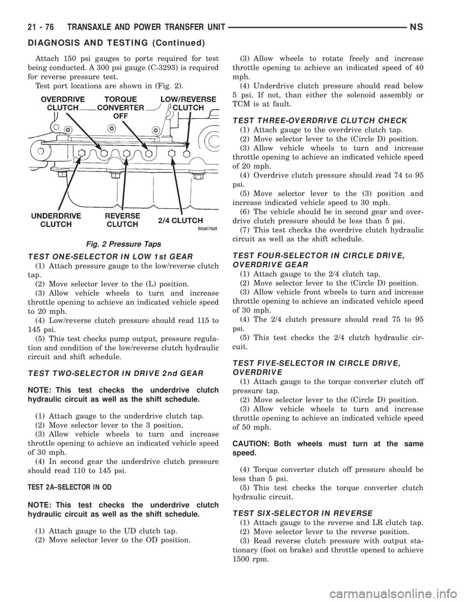
Test port locations are shown in (Fig. 2).
TEST ONE-SELECTOR IN LOW 1st GEAR
(1) Attach pressure gauge to the low/reverse clutch
tap.
(2) Move selector lever to the (L) position.
(3) Allow vehicle wheels to turn and increase
throttle opening to achieve an indicated vehicle speed
to 20 mph.
(4) Low/reverse clutch pressure should read 115 to
145 psi.
(5) This test checks pump output, pressure regula-
tion and condition of the low/reverse clutch hydraulic
circuit and shift schedule.
TEST TWO-SELECTOR IN DRIVE 2nd GEAR
NOTE: This test checks the underdrive clutch
hydraulic circuit as well as the shift schedule.
(1) Attach gauge to the underdrive clutch tap.
(2) Move selector lever to the 3 position.
(3) Allow vehicle wheels to turn and increase
throttle opening to achieve an indicated vehicle speed
of 30 mph.
(4) In second gear the underdrive clutch pressure
should read 110 to 145 psi.
TEST 2A±SELECTOR IN OD
NOTE: This test checks the underdrive clutch
hydraulic circuit as well as the shift schedule.
(1) Attach gauge to the UD clutch tap.
(2) Move selector lever to the OD position.(3) Allow wheels to rotate freely and increase
throttle opening to achieve an indicated speed of 40
mph.
(4) Underdrive clutch pressure should read below
5 psi. If not, than either the solenoid assembly or
TCM is at fault.
TEST THREE-OVERDRIVE CLUTCH CHECK
(1) Attach gauge to the overdrive clutch tap.
(2) Move selector lever to the (Circle D) position.
(3) Allow vehicle wheels to turn and increase
throttle opening to achieve an indicated vehicle speed
of 20 mph.
(4) Overdrive clutch pressure should read 74 to 95
psi.
(5) Move selector lever to the (3) position and
increase indicated vehicle speed to 30 mph.
(6) The vehicle should be in second gear and over-
drive clutch pressure should be less than 5 psi.
(7) This test checks the overdrive clutch hydraulic
circuit as well as the shift schedule.
TEST FOUR-SELECTOR IN CIRCLE DRIVE,
OVERDRIVE GEAR
(1) Attach gauge to the 2/4 clutch tap.
(2) Move selector lever to the (Circle D) position.
(3) Allow vehicle front wheels to turn and increase
throttle opening to achieve an indicated vehicle speed
of 30 mph.
(4) The 2/4 clutch pressure should read 75 to 95
psi.
(5) This test checks the 2/4 clutch hydraulic cir-
cuit.
TEST FIVE-SELECTOR IN CIRCLE DRIVE,
OVERDRIVE
(1) Attach gauge to the torque converter clutch off
pressure tap.
(2) Move selector lever to the (Circle D) position.
(3) Allow vehicle wheels to turn and increase
throttle opening to achieve an indicated vehicle speed
of 50 mph.
CAUTION: Both wheels must turn at the same
speed.
(4) Torque converter clutch off pressure should be
less than 5 psi.
(5) This test checks the torque converter clutch
hydraulic circuit.
TEST SIX-SELECTOR IN REVERSE
(1) Attach gauge to the reverse and LR clutch tap.
(2) Move selector lever to the reverse position.
(3) Read reverse clutch pressure with output sta-
tionary (foot on brake) and throttle opened to achieve
1500 rpm.
Fig. 2 Pressure Taps
21 - 76 TRANSAXLE AND POWER TRANSFER UNITNS
DIAGNOSIS AND TESTING (Continued)
Page 1642 of 1938

CAUTION: A certain amount of oil will drain out of
the transaxle when the drive shaft is removed.
(2) Remove right front drive shaft. Install a plug
into the right driveshaft seal hole. Refer to Group 2,
Suspension to remove or install wheel hub nut and
right drive shaft.
(3) Mark propeller shaft front flange.
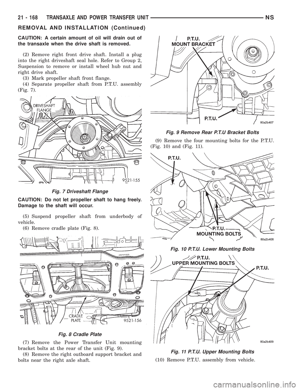
(4) Separate propeller shaft from P.T.U. assembly
(Fig. 7).
CAUTION: Do not let propeller shaft to hang freely.
Damage to the shaft will occur.
(5) Suspend propeller shaft from underbody of
vehicle.
(6) Remove cradle plate (Fig. 8).
(7) Remove the Power Transfer Unit mounting
bracket bolts at the rear of the unit (Fig. 9).
(8) Remove the right outboard support bracket and
bolts near the right axle shaft.(9) Remove the four mounting bolts for the P.T.U.
(Fig. 10) and (Fig. 11).
(10) Remove P.T.U. assembly from vehicle.
Fig. 7 Driveshaft Flange
Fig. 8 Cradle Plate
Fig. 9 Remove Rear P.T.U Bracket Bolts
Fig. 10 P.T.U. Lower Mounting Bolts
Fig. 11 P.T.U. Upper Mounting Bolts
21 - 168 TRANSAXLE AND POWER TRANSFER UNITNS
REMOVAL AND INSTALLATION (Continued)
Page 1720 of 1938

snow chain or other type of traction aid is not
to be used on the compact spare tire.
RADIAL-PLY TIRES
Radial-ply tires improve handling, tread life, ride
quality and decrease rolling resistance.
Radial-ply tires must always be used in sets of four
and under no circumstances should they be used on
the front only. They may be mixed with a temporary
spare tire when necessary. A maximum speed of 50
MPH is recommended while a temporary spare is in
use.
Radial-ply tires have the same load-carrying capac-
ity as other types of tires of the same size. They also
use the same recommended inflation pressures.
The use of oversized tires, either in the front or
rear of the vehicle, can cause vehicle drive train fail-
ure. This could also cause inaccurate wheel speed
signals when the vehicle is equipped with Anti-Lock
Brakes.
It is recommended that tires from different manu-
factures NOT be mixed. The proper tire pressure
should be maintained on all four tires. For proper
tire pressure refer to the Tire Inflation Pressure
Placard located in the glove box.
SPARE TIRE (TEMPORARY)
The temporary spare tire is designed for emer-
gency use only. The original tire should be repaired
and reinstalled at the first opportunity, or replaced
with a new. Do not exceed speeds of 50 MPH when
the temporary spare tire is in use on the vehicle.
Refer to the Owner's Manual for complete details.
TIRE INFLATION PRESSURES
WARNING: OVER OR UNDER INFLATED TIRES
CAN AFFECT VEHICLE HANDLING. THE TIRE CAN
FAIL SUDDENLY, RESULTING IN LOSS OF VEHICLE
CONTROL.
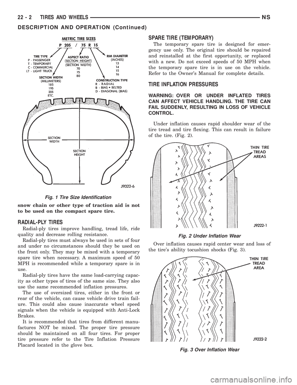
Under inflation causes rapid shoulder wear of the
tire tread and tire flexing. This can result in failure
of the tire. (Fig. 2).
Over inflation causes rapid center wear and loss of
the tire's ability tocushion shocks (Fig. 3).
Fig. 1 Tire Size Identification
Fig. 2 Under Inflation Wear
Fig. 3 Over Inflation Wear
22 - 2 TIRES AND WHEELSNS
DESCRIPTION AND OPERATION (Continued)
Page:
< prev 1-8 9-16 17-24