1996 CHRYSLER VOYAGER overheating
[x] Cancel search: overheatingPage 548 of 1938

FASTEN SEAT BELT LAMP OR TONE
CONTINUES FOR MORE THAN 10 SECONDS
AFTER SEAT BELTS ARE FASTENED AND
DRIVER'S DOOR IS CLOSED.
(1) Check left door ajar switch for no ground when
switch is depressed.
(a) If continuity replace door ajar switch.
(b) If NO continuity replace BCM for tone condi-
tion, or replace mechanical instrument panel for
lamp condition.
(c) Replace BCM for tone condition.
(d) Replace mechanical instrument cluster for
lamp condition.
NO TONE WHEN PARK OR HEADLAMPS ARE
ON AND DRIVER'S DOOR IS OPEN.
(1) Check left door ajar switch for good ground
when driver's door is open. Repair as necessary.
(2) Inspect BCM connectors and wires for proper
connection. If OK, replace BCM for tone condition.
DOME LAMP ON CHIME
The dome lamp on chime will warn the driver that
the dome lamps have been left on.
With the ignition is OFF:
²Driver's door OPEN (door ajar switch is closed to
ground)
²Dome lamps are ON (dome lamp switch is closed
to ground),
The chime will sound continuously until driver's
door is closed, dome lamps tuned OFF or until the
battery protection time out of 15 minutes has
expired. Refer Group 8L, Lamps proper procedures.
Chime rate: 168 to 192 chimes per minute.
ENGINE TEMPERATURE CRITICAL CHIME
The engine temperature critical chime will warn
the driver that the vehicle's engine is overheating.
While monitoring the coolant temperature, the Pow-
ertrain Control Module (PCM) will send on the CCD
bus as engine temperature every 1.376 seconds to the
Body Control Module (BCM). The BCM calculates
engine temperature and determines if a warning
should occur. This feature is functional only with the
Ignition Switch in the Run/Start position. On the
Diesel vehicles, the coolant temperature sensor is
read directly by the BCM.
When the engine temperature reaches 122ÉC
(252ÉF) or the diesel engine 112ÉC (234ÉF), the BCM
will chime one tone and the engine temperature lamp
comes ON. The BCM turns OFF the lamp when the
engine temperature reaches 117ÉC (242ÉF) or the die-
sel engine 108ÉC (226ÉF). The BCM will chime con-
tinuously when the engine temperature reaches
125ÉC (257ÉF) or diesel engine 116ÉC (241ÉF). The
chime will turn OFF after four minutes or when thetemperature reaches 117ÉC (242ÉF) or diesel engine
108ÉC (226ÉF), which ever occurs first.
EXTERIOR LAMPS ON CHIME
The exterior lamp on chime will warn the driver
that the exterior lights have been left on.
With the ignition switch OFF:
²Driver's door is open (door ajar switch is closed
to ground)
²Parking lamps or headlamps ON (parking lamp
switch is closed to ground)
The chime will sound until lights are turned OFF,
driver's door closed or until the battery protection
time out of 3 minutes has expired.
Refer to Group 8L, Lamps, for proper service pro-
cedures. Chime rate: 168 to 192 chimes per minute.
To test the exterior lamps left on function:
²Turn ignition off
²Remove ignition key
²Turn exterior lamps on with driver's door open.
Chime should sound until lamps are turned off or
driver's door is closed.
KEY-IN IGNITION CHIME
The key-in ignition chime will act as a warning to
the driver that the ignition key has been left in the
ignition switch.
With the ignition switch is in OFF position ONLY:
²Driver's door is open/ajar (door ajar switch is
closed to ground)
²Key is in the ignition switch (key-in ignition
switch is closed to ground)
The chime will sound until one of the above condi-
tions is removed. Chime rate: 168 to 192 chimes per
minute.
To test the key-in ignition function, insert key into
the ignition and open driver's door. Do not turn igni-
tion ON. Chime should sound until key is removed
from ignition or driver's door is closed.
LOW OIL PRESSURE CHIME OPERATION
The low oil pressure chime will warn the driver
that the engine oil pressure is low. The oil pressure
switch, will close to ground during a low oil pressure
condition. The oil pressure lamp will illuminate in
the message center. The body control module will
monitor the oil pressure switch and signal a low oil
pressure condition. A continuous four minute warn-
ing chime will sound and the oil pressure lamp will
come ON when the following conditions are met:
²Ignition on and engine not cranking
²Engine running at 420 to 480 rpm for 10 sec-
onds
²Oil pressure switch closed to ground for (1 sec-
ond minimum, 2 seconds maximum)
Chime rate: 168 to 192 chimes per minute.
8U - 2 CHIME WARNING/REMINDER SYSTEMNS/GS
DIAGNOSIS AND TESTING (Continued)
Page 1439 of 1938

(18) Remove the 3 previously loosened bolts
attaching the front bracket to the power steering
pump and separate the power steering pump from
the front bracket prior to removing the pump from
the vehicle.
(19) The power steering pump is removed from the
vehicle by pulling it out through the exhaust tunnel
area in the floor pan of the vehicle.
INSTALL
(1) Install power steering pump back in vehicle
using the reverse order of its removal through the
exhaust tunnel are of the vehicle.
(2) Install the power steering pump on its cast
mounting bracket and loosely install nut to hold
pump in place (Fig. 9).
(3) Install the front bracket on the power steering
pump and loosely install the 3 mounting bolts (Fig.
10). Then install the nut and bolt attaching the front
bracket to the cast bracket (Fig. 10).
(4) Tighten the 3 power steering pump mounting
bolts (Fig. 10) to a torque of 54 N´m (40 ft. lbs.).
NOTE: Before installing power steering fluid pres-
sure hose on power steering pump, inspect the
O-ring on the pressure hose for damage and
replace if necessary.
(5) Install the power steering fluid pressure line
onto the output fitting of the power steering pump
(Fig. 8). Tighten the pressure line to pump fitting
tube nut to a torque of 31 N´m (275 in. lbs.).
(6) Install the power steering fluid, low pressure
return hose on the power steering pump low pressure
fitting (Fig. 8).Be sure hose clamps are properly
reinstalled.
(7) Install the power steering fluid supply hose
from the power steering fluid reservoir, on the power
steering pump fluid fitting (Fig. 7).Be sure hose is
clear of accessory drive belts all hose clamps
are properly reinstalled.
(8) Install the power steering pump drive belt on
pulley. See Cooling, Group 7 for detailed installation
procedure.
(9) Install the accessory drive splash shield (Fig.
6).
(10) Install the power steering fluid return hose on
the steel tube at the front suspension cradle (Fig. 5).
(11) Install a screw type hose clamp on the power
steering hose to steel tube connection.Be sure hose
clamps are properly reinstalled.Tighten the screw
clamp to a torque of 2 N´m (18 in. lbs.).
CAUTION: The protective heat shield sleeves must
cover the entire rubber hose and hose to tube con-
nection portion of both the power steering fluid
pressure and return hoses (Fig. 5). This is requiredto prevent the overheating of the power steering
hoses.
(12) When used, properly position the protective
heat sleeves on the power steering hoses (Fig. 5).
Then, tie strap the heat sleeves to the power steering
hoses to keep them in their proper position.
(13) Install the exhaust pipe on the exhaust man-
ifold. Install all exhaust system hangers/isolators on
the exhaust system brackets.
(14) Connect the oxygen sensor wiring harness to
the vehicle wiring harness. Install wiring harness
grommet in the floor pan of the vehicle.
(15) Lower vehicle.
(16) Adjust the power steering pump drive belt.
See Cooling, Group 7 for detailed adjustment proce-
dure.
(17) Tighten the top nut and bottom bolt on the
power steering pump front mounting bracket (Fig. 3)
to a torque of 54 N´m (40 ft. lbs.).
CAUTION: Do not use automatic transmission fluid
in power steering system. Only use MoparT, Power
Steering Fluid, or equivalent.
(18) Fill the remote power steering pump fluid res-
ervoir to correct fluid level.
(19) Install cap on power steering fluid reservoir.
(20) Connect the negative battery cable on the
negative battery post.
(21) Start engine and turn steering wheel several
times from stop to stop to bleed air from fluid in sys-
tem. Stop engine, check fluid level, and inspect sys-
tem for leaks. See Checking Fluid Level.
3.0 LITER POWER STEERING PUMP
REMOVE
WARNING: POWER STEERING OIL, ENGINE COM-
PONENTS AND THE EXHAUST SYSTEM MAY BE
EXTREMELY HOT IF ENGINE HAS BEEN RUNNING.
DO NOT START ENGINE WITH ANY LOOSE OR DIS-
CONNECTED HOSES. DO NOT ALLOW HOSES TO
TOUCH HOT EXHAUST MANIFOLD OR CATALYST.
(1) Remove the (-) negative battery cable from the
battery and isolate cable.
(2) Remove cap from power steering fluid reser-
voir.
(3) Using a siphon pump, remove as much power
steering fluid as possible from the power steering
fluid reservoir.
NSSTEERING 19 - 13
REMOVAL AND INSTALLATION (Continued)
Page 1441 of 1938

(13) Remove the power steering fluid return hose
(Fig. 15) from the power steering pump.
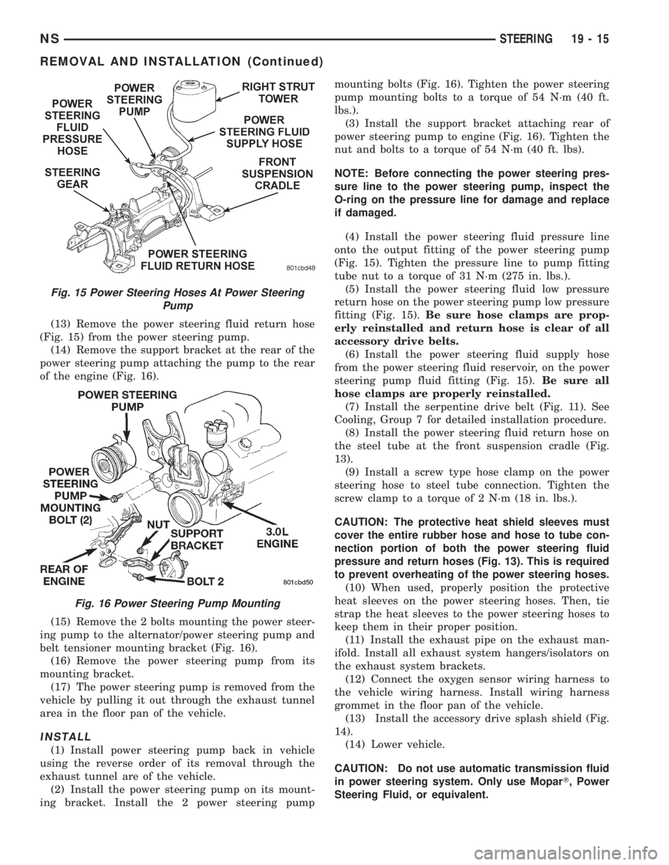
(14) Remove the support bracket at the rear of the
power steering pump attaching the pump to the rear
of the engine (Fig. 16).
(15) Remove the 2 bolts mounting the power steer-
ing pump to the alternator/power steering pump and
belt tensioner mounting bracket (Fig. 16).
(16) Remove the power steering pump from its
mounting bracket.
(17) The power steering pump is removed from the
vehicle by pulling it out through the exhaust tunnel
area in the floor pan of the vehicle.
INSTALL
(1) Install power steering pump back in vehicle
using the reverse order of its removal through the
exhaust tunnel are of the vehicle.
(2) Install the power steering pump on its mount-
ing bracket. Install the 2 power steering pumpmounting bolts (Fig. 16). Tighten the power steering
pump mounting bolts to a torque of 54 N´m (40 ft.
lbs.).
(3) Install the support bracket attaching rear of
power steering pump to engine (Fig. 16). Tighten the
nut and bolts to a torque of 54 N´m (40 ft. lbs).
NOTE: Before connecting the power steering pres-
sure line to the power steering pump, inspect the
O-ring on the pressure line for damage and replace
if damaged.
(4) Install the power steering fluid pressure line
onto the output fitting of the power steering pump
(Fig. 15). Tighten the pressure line to pump fitting
tube nut to a torque of 31 N´m (275 in. lbs.).
(5) Install the power steering fluid low pressure
return hose on the power steering pump low pressure
fitting (Fig. 15).Be sure hose clamps are prop-
erly reinstalled and return hose is clear of all
accessory drive belts.
(6) Install the power steering fluid supply hose
from the power steering fluid reservoir, on the power
steering pump fluid fitting (Fig. 15).Be sure all
hose clamps are properly reinstalled.
(7) Install the serpentine drive belt (Fig. 11). See
Cooling, Group 7 for detailed installation procedure.
(8) Install the power steering fluid return hose on
the steel tube at the front suspension cradle (Fig.
13).
(9) Install a screw type hose clamp on the power
steering hose to steel tube connection. Tighten the
screw clamp to a torque of 2 N´m (18 in. lbs.).
CAUTION: The protective heat shield sleeves must
cover the entire rubber hose and hose to tube con-
nection portion of both the power steering fluid
pressure and return hoses (Fig. 13). This is required
to prevent overheating of the power steering hoses.
(10) When used, properly position the protective
heat sleeves on the power steering hoses. Then, tie
strap the heat sleeves to the power steering hoses to
keep them in their proper position.
(11) Install the exhaust pipe on the exhaust man-
ifold. Install all exhaust system hangers/isolators on
the exhaust system brackets.
(12) Connect the oxygen sensor wiring harness to
the vehicle wiring harness. Install wiring harness
grommet in the floor pan of the vehicle.
(13) Install the accessory drive splash shield (Fig.
14).
(14) Lower vehicle.
CAUTION: Do not use automatic transmission fluid
in power steering system. Only use MoparT, Power
Steering Fluid, or equivalent.
Fig. 15 Power Steering Hoses At Power Steering
Pump
Fig. 16 Power Steering Pump Mounting
NSSTEERING 19 - 15
REMOVAL AND INSTALLATION (Continued)
Page 1447 of 1938

(6) Install the power steering fluid return hose on
the steel tube at the front suspension cradle (Fig.
26).
(7) Install a screw type hose clamp on the power
steering hose to steel tube connection. Tighten the
screw clamp to a torque of 2 N´m (18 in. lbs.).
CAUTION: The protective heat sleeves must cover
the entire rubber hose and hose to tube connection
portion of both the power steering fluid pressure
and return hoses (Fig. 26).
(8) When used, properly position the protective
heat sleeves on the power steering hoses. Then, tie
strap the heat sleeves to the power steering hoses to
keep them in their proper position.
(9) After hoses are installed and power steering
system is filled with fluid and cap is installed on res-
ervoir. Start the engine and check for leaks. (See
Pump Installation).
POWER STEERING FLUID RETURN HOSE
Service all power steering hoses with vehicle raised
on hoist. Cap all open ends of hoses, power steering
pump fittings and steering gear ports to prevent
entry of foreign material into the components.
WARNING: POWER STEERING OIL, ENGINE
PARTS AND THE EXHAUST SYSTEM MAY BE
EXTREMELY HOT IF ENGINE HAS BEEN RUNNING.
DO NOT START ENGINE WITH ANY LOOSE OR DIS-
CONNECTED HOSES. DO NOT ALLOW HOSES TO
TOUCH HOT EXHAUST MANIFOLD OR CATALYST.
For part reference and part location for the vehicle
that is being serviced, refer to the following figure
numbers. These show the hose bracket locations,
hose routings and fitting locations by the engine
application of the vehicle. Use these figure numbers
when referring to the removal or installation proce-
dures for the power steering hoses listed below.
REMOVE
(1) Remove cap from power steering fluid reser-
voir.
(2) Using a siphon pump, remove as much power
steering fluid as possible from the power steering
fluid reservoir.
(3) Raise vehicle See Hoisting, Group 0. Put oil
drain pan under vehicle to catch power steering fluid.
(4) Raise the insulating heat sleeve on the power
steering hoses to expose the hose to steel tube con-
nection. Remove hose clamp where rubber portion of
power steering fluid return hose attaches to steel
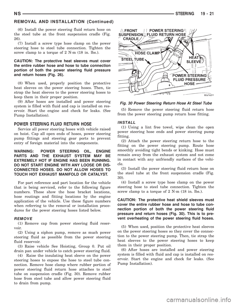
tube on suspension cradle (Fig. 30). Remove rubber
hose from steel tube and allow power steering fluid
to drain from pump.(5) Remove the power steering fluid return hose
from the power steering pump return hose fitting.
INSTALL
(1) Using a lint free towel, wipe clean the open
power steering hose ends and power steering pump
fitting.
(2) Attach the power steering return hose to the
fitting on the power steering pump. Route hose
smoothly avoiding tight bends or kinking. Hose must
remain away from the exhaust system and not come
in contact with any unfriendly surfaces of the vehi-
cle.
(3) Install the power steering fluid return hose on
the steel tube at the front suspension cradle (Fig.
30).
(4) Install a screw type hose clamp on the power
steering hose to steel tube connection. Tighten the
screw clamp to a torque of 2 N´m (18 in. lbs.).
CAUTION: The protective heat shield sleeves must
cover the entire rubber hose and hose to tube con-
nection portion of both the power steering fluid
pressure and return hoses (Fig. 30). This is to pre-
vent overheating of the power steering fluid hoses.
(5) When used, position the protective heat sleeves
on the power steering hoses so they cover the connec-
tion to the power steering pump. Then, tie strap the
heat sleeves to the power steering hoses to keep
them in their proper position.
(6) After hoses are installed and power steering
system is filled with fluid and cap is installed on res-
ervoir. Start the engine and check for leaks. (See
Pump Installation).
Fig. 30 Power Steering Return Hose At Steel Tube
NSSTEERING 19 - 21
REMOVAL AND INSTALLATION (Continued)
Page 1925 of 1938

ulated shop air to the metal back- pressure fitting on
the EGR valve.
(6) By hand, open the throttle to the wide open
position. AirSHOULD NOT BE HEARDemitting
from the intake manifold while applying air pressure
at the back-pressure fitting.
(7) If airCAN BE HEARDemitting from the
intake manifold, the poppet valve (Fig. 4) is leaking
at the bottom of the EGR valve. Replace the EGR
valve. Note: The EGR valve, valve control and
attaching hoses are serviced as one assembly. Refer
to EGR Valve Removal/Installation in this group. Do
not attempt clean the old EGR valve.
EGR VALVE CONTROL (TRANSDUCER) TEST
TESTING ELECTRICAL SOLENOID PORTION
OF VALVE
This is not to be used as a complete test of the
EGR system.
Electrical operation of the valve should be checked
with the DRB scan tool. Refer to the appropriate
Powertrain Diagnostic Procedures service manual for
operation of the DRB scan tool. Replace solenoid if
necessary, unit serviced only as an assembly.
TESTING VACUUM TRANSDUCER PORTION
OF VALVE
The first part of this test will determine if the
transducer diaphragm at the back-pressure side of
the valve has ruptured or is leaking. The second part
of the test will determine if engine vacuum (full-man-
ifold) is flowing from the inlet to the outlet side of
the valve. This is not to be used as a complete test of
the EGR system.
(1) Disconnect the rubber back-pressure hose from
the fitting at the bottom of EGR valve (Fig. 4).
(2) Connect a hand-held vacuum pump to this fit-
ting.
(3) Apply 10 inches of vacuum to this fitting.
(4) If vacuum falls off, the valve diaphragm is
leaking.
(5) Replace the EGR valve assembly. Proceed to
next step for further testing.
(6) Remove the rubber hose at the vacuuminlet
fitting (Fig. 4) on the EGR valve.
(7) Connect a vacuum gauge to this disconnected
hose.
(8) Start the engine and bring to operating tem-
perature. Hold engine speed at approximately 1500
rpm.
(9) Check for steady engine vacuum (full-manifold)
at this hose.
(10) If engine vacuum (full-manifold) is not
present, check vacuum line to engine and repair as
necessary before proceeding to next step.(11) Reconnect the rubber hose to the vacuum
inletfitting (Fig. 4) on the EGR valve.
(12) Disconnect the rubber hose at the vacuum
outletfitting (Fig. 4) on the EGR valve.
(13) Connect a vacuum gauge to this fitting.
(14) Disconnect the electrical connector (Fig. 4) at
the valve control. This will simulate an open circuit
(no ground from the PCM) at the valve.
(15) Start the engine and bring to operating tem-
perature.
(16) Hold the engine speed to approximately 2000
rpm while checking for engine vacuum (full-manifold)
at this fitting.To allow full manifold vacuum to
flow through the valve, exhaust back-pressure
must be present at valve. It must be high
enough to hold the bleed valve in the trans-
ducer portion of the valve closed.Have a helper
momentarily (a second or two) hold a rag over the
tailpipe opening to build some exhaust back-pressure
while observing the vacuum gauge. Heavy gloves
should be worn.Do not cover the tailpipe open-
ing for an extended period of time as damage to
components or overheating may result.
(17) As temporary back-pressure is built, full man-
ifold vacuum should be observed at the vacuum out-
let fitting. Without back-pressure, and engine at
approximately 2000 rpm, the gauge reading will be
low. This low reading is normal. At idle speed, the
gauge reading will be erratic. This is also normal.
(18) If full manifold vacuum is not present at the
outlet fitting, but was present at the inlet fitting,
replace the valve. Note: The EGR valve, valve control
and attaching hoses are serviced as one assembly.
Refer to EGR Valve Removal/Installation in this
group.
REMOVAL AND INSTALLATION
EGR VALVE SERVICEÐ3.0L ENGINES
The EGR valve and Electrical EGR Transducer are
serviced as an assembly.
REMOVAL
(1) Disconnect the electric and vacuum connectors
from the electric EGR transducer (Fig. 6).
(2) Remove EGR valve mounting bolts.
(3) Clean all gasket surfaces and discard old gas-
kets. Check for any signs of leakage or cracked sur-
faces. Repair or replace as necessary.
INSTALLATION
(1) Install EGR valve and new gasket on intake
manifold. Tighten mounting bolts to 22 N´m (200 in.
lbs.) torque.
(2) Connect the electrical and vacuum connectors
to the electric EGR transducer.
NSEMISSION CONTROL SYSTEMS 25 - 21
DIAGNOSIS AND TESTING (Continued)