1996 CHRYSLER VOYAGER alarm
[x] Cancel search: alarmPage 1413 of 1938
BOOST PRESSURE SENSOR
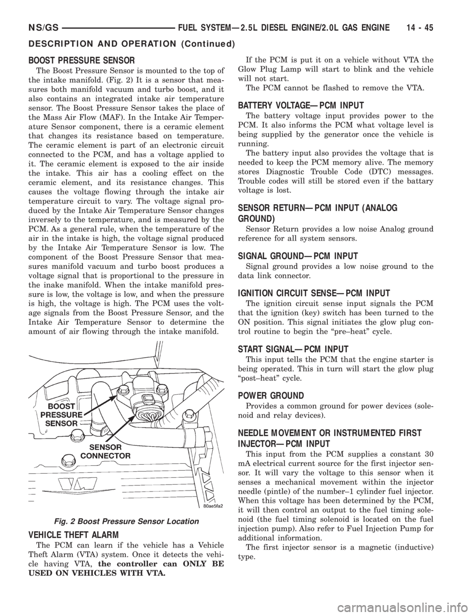
The Boost Pressure Sensor is mounted to the top of
the intake manifold. (Fig. 2) It is a sensor that mea-
sures both manifold vacuum and turbo boost, and it
also contains an integrated intake air temperature
sensor. The Boost Pressure Sensor takes the place of
the Mass Air Flow (MAF). In the Intake Air Temper-
ature Sensor component, there is a ceramic element
that changes its resistance based on temperature.
The ceramic element is part of an electronic circuit
connected to the PCM, and has a voltage applied to
it. The ceramic element is exposed to the air inside
the intake. This air has a cooling effect on the
ceramic element, and its resistance changes. This
causes the voltage flowing through the intake air
temperature circuit to vary. The voltage signal pro-
duced by the Intake Air Temperature Sensor changes
inversely to the temperature, and is measured by the
PCM. As a general rule, when the temperature of the
air in the intake is high, the voltage signal produced
by the Intake Air Temperature Sensor is low. The
component of the Boost Pressure Sensor that mea-
sures manifold vacuum and turbo boost produces a
voltage signal that is proportional to the pressure in
the inake manifold. When the intake manifold pres-
sure is low, the voltage is low, and when the pressure
is high, the voltage is high. The PCM uses the volt-
age signals from the Boost Pressure Sensor, and the
Intake Air Temperature Sensor to determine the
amount of air flowing through the intake manifold.
VEHICLE THEFT ALARM
The PCM can learn if the vehicle has a Vehicle
Theft Alarm (VTA) system. Once it detects the vehi-
cle having VTA,the controller can ONLY BE
USED ON VEHICLES WITH VTA.If the PCM is put it on a vehicle without VTA the
Glow Plug Lamp will start to blink and the vehicle
will not start.
The PCM cannot be flashed to remove the VTA.
BATTERY VOLTAGEÐPCM INPUT
The battery voltage input provides power to the
PCM. It also informs the PCM what voltage level is
being supplied by the generator once the vehicle is
running.
The battery input also provides the voltage that is
needed to keep the PCM memory alive. The memory
stores Diagnostic Trouble Code (DTC) messages.
Trouble codes will still be stored even if the battary
voltage is lost.
SENSOR RETURNÐPCM INPUT (ANALOG
GROUND)
Sensor Return provides a low noise Analog ground
reference for all system sensors.
SIGNAL GROUNDÐPCM INPUT
Signal ground provides a low noise ground to the
data link connector.
IGNITION CIRCUIT SENSEÐPCM INPUT
The ignition circuit sense input signals the PCM
that the ignition (key) switch has been turned to the
ON position. This signal initiates the glow plug con-
trol routine to begin the ªpre±heatº cycle.
START SIGNALÐPCM INPUT
This input tells the PCM that the engine starter is
being operated. This in turn will start the glow plug
ªpost±heatº cycle.
POWER GROUND
Provides a common ground for power devices (sole-
noid and relay devices).
NEEDLE MOVEMENT OR INSTRUMENTED FIRST
INJECTORÐPCM INPUT
This input from the PCM supplies a constant 30
mA electrical current source for the first injector sen-
sor. It will vary the voltage to this sensor when it
senses a mechanical movement within the injector
needle (pintle) of the number±1 cylinder fuel injector.
When this voltage has been determined by the PCM,
it will then control an output to the fuel timing sole-
noid (the fuel timing solenoid is located on the fuel
injection pump). Also refer to Fuel Injection Pump for
additional information.
The first injector sensor is a magnetic (inductive)
type.
Fig. 2 Boost Pressure Sensor Location
NS/GSFUEL SYSTEMÐ2.5L DIESEL ENGINE/2.0L GAS ENGINE 14 - 45
DESCRIPTION AND OPERATION (Continued)
Page 1907 of 1938
Adaptive Fuel Factor
Barometric Pressure
Engine Speed
Module Spark Advance
Speed Control Target
Intake Air Temp Degrees
Intake Air Temp Volts
Charging System Goal
Theft Alarm Status
Map Sensor Voltage
Vehicle Speed
Throttle Opening (percentage)
TPS Calculated
Cam Timing Position
Target Idle
Time From Start To Run
Run Time At Stall
Injector Pulse-width
Upstream O2S Volts
Downstream O2S Volts
Closed Loop Timer
Short Term Adaptive
Current Adaptive Cell
Adaptive Memory Cell 0
Adaptive Memory Cell 1
Adaptive Memory Cell 2
Adaptive Memory Cell 3
Adaptive Memory Cell 4
Adaptive Memory Cell 5
Adaptive Memory Cell 6
Adaptive Memory Cell 7
Adaptive Memory Cell 8
Adaptive Memory Cell 9
Adaptive Memory Cell 10
Adaptive Memory Cell 11
Adaptive Memory Cell 12
Adaptive Memory Cell 13
Adaptive Memory Cell 14
Adaptive Memory Cell 15
Purge Free Idle Cell
Purge Free Cell 2 (corresponds to memory cell 2)
Purge Free Cell 3 (corresponds to memory cell 5)
Target IAC Steps
Retard Cylinder (1)
Retard Cylinder (2)
Retard Cylinder (3)
Retard Cylinder (4)
Retard Cylinder (5)
Retard Cylinder (6)CIRCUIT ACTUATION TEST MODE
The Circuit Actuation Test Mode checks for proper
operation of output circuits or devices the Powertrain
Control Module (PCM) may not internally recognize.
The PCM attempts to activate these outputs and
allow an observer to verify proper operation. Most of
the tests provide an audible or visual indication of
device operation (click of relay contacts, fuel spray,
etc.). Except for intermittent conditions, if a device
functions properly during testing, assume the device,
its associated wiring, and driver circuit work cor-
rectly.
DIAGNOSTIC TROUBLE CODES
A Diagnostic Trouble Code (DTC) indicates the
PCM has recognized an abnormal condition in the
system.
The preferred and most accurate method of retriev-
ing a DTC is by using the DRB scan tool. The scan
tool supplies detailed diagnostic information which
can be used to more accurately diagnose causes for a
DTC.
Remember that DTC's are the results of a sys-
tem or circuit failure, but do not directly iden-
tify the failed component or components.
NOTE: For a list of DTC's, refer to the charts in this
section.
BULB CHECK
Each time the ignition key is turned to the ON
position, the malfunction indicator (check engine)
lamp on the instrument panel should illuminate for
approximately 2 seconds then go out. This is done for
a bulb check.
OBTAINING DTC'S USING DRB SCAN TOOL
(1) Connect the DRB scan tool to the data link
(diagnostic) connector. This connector is located in
the passenger compartment; at the lower edge of
instrument panel; near the steering column.
(2) Turn the ignition switch on and access the
ªRead Faultº screen.
(3) Record all the DTC's and ªfreeze frameº infor-
mation shown on the DRB scan tool.
(4) To erase DTC's, use the ªErase Trouble Codeº
data screen on the DRB scan tool.Do not erase any
DTC's until problems have been investigated
and repairs have been performed.
NSEMISSION CONTROL SYSTEMS 25 - 3
DESCRIPTION AND OPERATION (Continued)
Page 1932 of 1938
Generic Scan
Tool CodeDRB III Scan Tool Display
EEPROM Plausibility Ver Number Not Corresponding
P1685 Vehicle Theft Alarm Code Line Breakdown
P1690 Fan Control Open Circuit Fan #1
Fan Control Open Circuit Fan #2
Fan Control Short Circuit Fan #1
Fan Control Short Circuit Fan #2
P1695 A/C System Pressure Sensor Signal High Exceeded
A/C System Pressure Sensor Signal Low Exceeded
A/C System Pressure Supply Signal High Exceeded
A/C System Pressure Supply Signal Low Exceeded
P1703 Brake Signal Plaus With Redundant Contact
P1740 Clutch Signal Plausibilty
P1725 Inductive Aux. Speed Sensor Dynamic Plausibilty
Inductive Aux. Speed Sensor Overspeed Recognition
Inductive Aux Speed Sensor Plausibilty
Inductive Aux. Speed Sensor Static Plausibilty
25 - 4 EMISSION CONTROL SYSTEMNS/GS
DESCRIPTION AND OPERATION (Continued)