1996 CHRYSLER VOYAGER PTU
[x] Cancel search: PTUPage 1924 of 1938

EGR GAS FLOW TEST
Use the following test procedure to determine if
exhaust gas is flowing through the EGR valve. It can
also be used to determine if the EGR tube is plugged,
or the system passages in the intake or exhaust man-
ifolds are plugged.
This is not to be used as a complete test of the
EGR system.
The engine must be started, running and warmed
to operating temperature for this test.
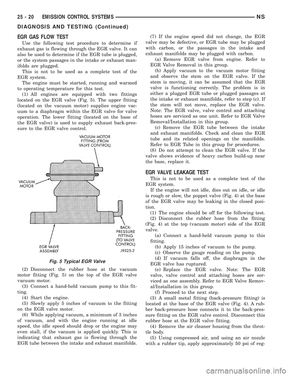
(1) All engines are equipped with two fittings
located on the EGR valve (Fig. 5). The upper fitting
(located on the vacuum motor) supplies engine vac-
uum to a diaphragm within the EGR valve for valve
operation. The lower fitting (located on the base of
the EGR valve) is used to supply exhaust back-pres-
sure to the EGR valve control.
(2) Disconnect the rubber hose at the vacuum
motor fitting (Fig. 5) on the top of the EGR valve
vacuum motor.
(3) Connect a hand-held vacuum pump to this fit-
ting.
(4) Start the engine.
(5) Slowly apply 5 inches of vacuum to the fitting
on the EGR valve motor.
(6) While applying vacuum, a minimum of 3 inches
of vacuum, and with the engine running at idle
speed, the idle speed should drop or the engine may
even stall, if the vacuum is applied quickly. This is
indicating that exhaust gas is flowing through the
EGR tube between the intake and exhaust manifolds.(7) If the engine speed did not change, the EGR
valve may be defective, or EGR tube may be plugged
with carbon, or the passages in the intake and
exhaust manifolds may be plugged with carbon.
(a) Remove EGR valve from engine. Refer to
EGR Valve Removal in this group.
(b) Apply vacuum to the vacuum motor fitting
and observe the stem on the EGR valve. If the
stem is moving, it can be assumed that the EGR
valve is functioning correctly. The problem is in
either a plugged EGR tube or plugged passages at
the intake or exhaust manifolds, refer to step (c). If
the stem will not move, replace the EGR valve.
Note: The EGR valve, valve control and attaching
hoses are serviced as one unit. Refer to EGR Valve
Removal/Installation in this group.
(c) Remove the EGR tube between the intake
and exhaust manifolds. Check and clean the EGR
tube and its related openings on the manifolds.
Refer to EGR Tube in this group for procedures.
(8) Do not attempt to clean the EGR valve. If the
valve shows evidence of heavy carbon build-up near
the base, replace it.
EGR VALVE LEAKAGE TEST
This is not to be used as a complete test of the
EGR system.
If the engine will not idle, dies out on idle, or idle
is rough or slow, the poppet valve (Fig. 4) at the base
of the EGR valve may be leaking in the closed posi-
tion.
(1) The engine should be off for the following test.
(2) Disconnect the rubber hose from the fitting
(Fig. 4) at the top (vacuum motor) side of the EGR
valve.
(a) Connect a hand-held vacuum pump to this
fitting.
(b) Apply 15 inches of vacuum to the pump.
(c) Observe the gauge reading on the pump.
(d) If vacuum falls off, the diaphragm in the
EGR valve has ruptured.
(e) Replace the EGR valve. Note: The EGR
valve, valve control and attaching hoses are ser-
viced as one assembly. Refer to EGR Valve Remov-
al/Installation in this group.
(f) Proceed to the next step.
(3) A small metal fitting (back-pressure fitting) is
located at the base of the EGR valve (Fig. 4). A rub-
ber back-pressure hose connects it to the back-pres-
sure fitting on the EGR valve control. Disconnect this
rubber hose at the EGR valve fitting.
(4) Remove the air cleaner housing from the throt-
tle body.
(5) Using compressed air, and using an air nozzle
with a rubber tip, apply approximately 50 psi of reg-
Fig. 5 Typical EGR Valve
25 - 20 EMISSION CONTROL SYSTEMSNS
DIAGNOSIS AND TESTING (Continued)
Page 1925 of 1938

ulated shop air to the metal back- pressure fitting on
the EGR valve.
(6) By hand, open the throttle to the wide open
position. AirSHOULD NOT BE HEARDemitting
from the intake manifold while applying air pressure
at the back-pressure fitting.
(7) If airCAN BE HEARDemitting from the
intake manifold, the poppet valve (Fig. 4) is leaking
at the bottom of the EGR valve. Replace the EGR
valve. Note: The EGR valve, valve control and
attaching hoses are serviced as one assembly. Refer
to EGR Valve Removal/Installation in this group. Do
not attempt clean the old EGR valve.
EGR VALVE CONTROL (TRANSDUCER) TEST
TESTING ELECTRICAL SOLENOID PORTION
OF VALVE
This is not to be used as a complete test of the
EGR system.
Electrical operation of the valve should be checked
with the DRB scan tool. Refer to the appropriate
Powertrain Diagnostic Procedures service manual for
operation of the DRB scan tool. Replace solenoid if
necessary, unit serviced only as an assembly.
TESTING VACUUM TRANSDUCER PORTION
OF VALVE
The first part of this test will determine if the
transducer diaphragm at the back-pressure side of
the valve has ruptured or is leaking. The second part
of the test will determine if engine vacuum (full-man-
ifold) is flowing from the inlet to the outlet side of
the valve. This is not to be used as a complete test of
the EGR system.
(1) Disconnect the rubber back-pressure hose from
the fitting at the bottom of EGR valve (Fig. 4).
(2) Connect a hand-held vacuum pump to this fit-
ting.
(3) Apply 10 inches of vacuum to this fitting.
(4) If vacuum falls off, the valve diaphragm is
leaking.
(5) Replace the EGR valve assembly. Proceed to
next step for further testing.
(6) Remove the rubber hose at the vacuuminlet
fitting (Fig. 4) on the EGR valve.
(7) Connect a vacuum gauge to this disconnected
hose.
(8) Start the engine and bring to operating tem-
perature. Hold engine speed at approximately 1500
rpm.
(9) Check for steady engine vacuum (full-manifold)
at this hose.
(10) If engine vacuum (full-manifold) is not
present, check vacuum line to engine and repair as
necessary before proceeding to next step.(11) Reconnect the rubber hose to the vacuum
inletfitting (Fig. 4) on the EGR valve.
(12) Disconnect the rubber hose at the vacuum
outletfitting (Fig. 4) on the EGR valve.
(13) Connect a vacuum gauge to this fitting.
(14) Disconnect the electrical connector (Fig. 4) at
the valve control. This will simulate an open circuit
(no ground from the PCM) at the valve.
(15) Start the engine and bring to operating tem-
perature.
(16) Hold the engine speed to approximately 2000
rpm while checking for engine vacuum (full-manifold)
at this fitting.To allow full manifold vacuum to
flow through the valve, exhaust back-pressure
must be present at valve. It must be high
enough to hold the bleed valve in the trans-
ducer portion of the valve closed.Have a helper
momentarily (a second or two) hold a rag over the
tailpipe opening to build some exhaust back-pressure
while observing the vacuum gauge. Heavy gloves
should be worn.Do not cover the tailpipe open-
ing for an extended period of time as damage to
components or overheating may result.
(17) As temporary back-pressure is built, full man-
ifold vacuum should be observed at the vacuum out-
let fitting. Without back-pressure, and engine at
approximately 2000 rpm, the gauge reading will be
low. This low reading is normal. At idle speed, the
gauge reading will be erratic. This is also normal.
(18) If full manifold vacuum is not present at the
outlet fitting, but was present at the inlet fitting,
replace the valve. Note: The EGR valve, valve control
and attaching hoses are serviced as one assembly.
Refer to EGR Valve Removal/Installation in this
group.
REMOVAL AND INSTALLATION
EGR VALVE SERVICEÐ3.0L ENGINES
The EGR valve and Electrical EGR Transducer are
serviced as an assembly.
REMOVAL
(1) Disconnect the electric and vacuum connectors
from the electric EGR transducer (Fig. 6).
(2) Remove EGR valve mounting bolts.
(3) Clean all gasket surfaces and discard old gas-
kets. Check for any signs of leakage or cracked sur-
faces. Repair or replace as necessary.
INSTALLATION
(1) Install EGR valve and new gasket on intake
manifold. Tighten mounting bolts to 22 N´m (200 in.
lbs.) torque.
(2) Connect the electrical and vacuum connectors
to the electric EGR transducer.
NSEMISSION CONTROL SYSTEMS 25 - 21
DIAGNOSIS AND TESTING (Continued)