1996 CHRYSLER VOYAGER brakes
[x] Cancel search: brakesPage 1455 of 1938
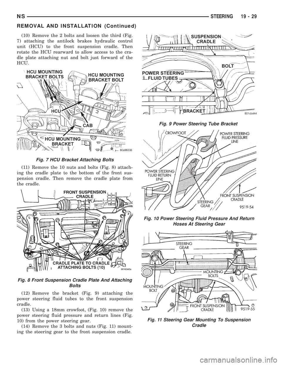
(10) Remove the 2 bolts and loosen the third (Fig.
7) attaching the antilock brakes hydraulic control
unit (HCU) to the front suspension cradle. Then
rotate the HCU rearward to allow access to the cra-
dle plate attaching nut and bolt just forward of the
HCU.
(11) Remove the 10 nuts and bolts (Fig. 8) attach-
ing the cradle plate to the bottom of the front sus-
pension cradle. Then remove the cradle plate from
the cradle.
(12) Remove the bracket (Fig. 9) attaching the
power steering fluid tubes to the front suspension
cradle.
(13) Using a 18mm crowfoot, (Fig. 10) remove the
power steering fluid pressure and return lines (Fig.
10) from the power steering gear.
(14) Remove the 3 bolts and nuts (Fig. 11) mount-
ing the steering gear to the front suspension cradle.
Fig. 7 HCU Bracket Attaching Bolts
Fig. 8 Front Suspension Cradle Plate And Attaching
Bolts
Fig. 9 Power Steering Tube Bracket
Fig. 10 Power Steering Fluid Pressure And Return
Hoses At Steering Gear
Fig. 11 Steering Gear Mounting To Suspension
Cradle
NSSTEERING 19 - 29
REMOVAL AND INSTALLATION (Continued)
Page 1492 of 1938
(13) Remove the pan and clean all sealant from
the pan and transaxle mating surfaces. Clean the
magnet and the inside of the pan.
(14) Separate the filter from the valve body to
allow additional fluid to drain from the transaxle.
Inspect the filter O-ring for any damage and replace
as necessary.
(15) After the transaxle has stopped draining,
reinstall the filter and O-ring.
(16) Apply a 1/8 inch bead of Mopar RTV Sealant
to the mounting flange of the transaxle oil pan.
Apply RTV Sealant to the underside of the attaching
bolts. Attach the oil pan to the transaxle. Tighten the
bolts to 19 N²m (165 in. lbs.).
(17) Lower the vehicle and add 4 Quarts of Mopar
ATF Plus 3 Type 7176 transaxle fluid.
(18) Start the engine and allow it to idle for a min-
imum of one minute. With the parking brake applied,
press your foot on the service brake and cycle the
transaxle from park to all gear positions ending in
neutral or park.
(19) Check the transaxle fluid level and add an
appropriate amount to bring the transaxle fluid level
to 3mm (1/8 in.) below the ADD mark on the dip-
stick.
(20) Recheck the fluid level after the transaxle is
at normal operating temperature. The level should be
in the HOT range.
FLUID DRAIN AND REFILL
(1) Raise vehicle on a hoist (See Group 0, Lubrica-
tion). Place a drain container with a large opening,
under transaxle oil pan.
(2) Loosen pan bolts and tap the pan at one corner
to break it loose allowing fluid to drain, then remove
the oil pan.
(3) Install a new filter and gasket on bottom of the
valve body and tighten retaining screws to 5 N´m (40
inch-pounds).
(4) Clean the oil pan and magnet. Reinstall pan
using new sealant. Tighten oil pan bolts to 19 N´m
(165 in. lbs.).
(5) Pour four quarts of Mopar ATF PLUS 3 (Auto-
matic Transmission Fluid) Type 7176 through the
dipstick opening.
(6) Start engine and allow to idle for at least one
minute. Then, with parking and service brakes
applied, move selector lever momentarily to each
position, ending in the park or neutral position.
(7) Add sufficient fluid to bring level to 1/8 inch
below the ADD mark.
(8) Recheck fluid level after transaxle is at normal
operating temperature. The level should be in the
HOT region.
ALUMINUM THREAD REPAIR
Damaged or worn threads in the aluminum transaxle
case and valve body can be repaired by the use of Heli-
Coils, or equivalent. This repair consists of drilling out
the worn-out damaged threads. Then tapping the hole
with a Heli-Coil tap, or equivalent, and installing a
Heli-Coil insert, or equivalent, into the hole. This
brings the hole back to its original thread size.
Heli-Coil, or equivalent, tools and inserts are readily
available from most automotive parts suppliers.
FLUSHING COOLERS AND TUBES
When a transaxle failure has contaminated the
fluid, the oil cooler(s) must be flushed. The cooler
bypass valve in the transaxle must be replaced also.
The torque converter must also be replaced with an
exchange unit. This will ensure that metal particles
or sludged oil are not later transferred back into the
reconditioned (or replaced) transaxle.
The recommended procedure for flushing the cool-
ers and tubes is to use Tool 6906A Cooler Flusher.
WARNING: WEAR PROTECTIVE EYEWEAR THAT
MEETS THE REQUIREMENTS OF OSHA AND ANSI
Z87.1±1968. WEAR STANDARD INDUSTRIAL RUB-
BER GLOVES.
KEEP LIGHTED CIGARETTES, SPARKS, FLAMES,
AND OTHER IGNITION SOURCES AWAY FROM THE
AREA TO PREVENT THE IGNITION OF COMBUSTI-
BLE LIQUIDS AND GASES. KEEP A CLASS (B) FIRE
EXTINGUISHER IN THE AREA WHERE THE
FLUSHER WILL BE USED.
KEEP THE AREA WELL VENTILATED.
DO NOT LET FLUSHING SOLVENT COME IN CON-
TACT WITH YOUR EYES OR SKIN: IF EYE CONTAM-
INATION OCCURS, FLUSH EYES WITH WATER FOR
15 TO 20 SECONDS. REMOVE CONTAMINATED
CLOTHING AND WASH AFFECTED SKIN WITH
SOAP AND WATER. SEEK MEDICAL ATTENTION.
COOLER FLUSH USING TOOL 6906A
(1) Remove cover plate filler plug on Tool 6906A.
Fill reservoir 1/2 to 3/4 full of fresh flushing solution.
Flushing solvents are petroleum based solutions gen-
erally used to clean automatic transmission compo-
nents.DO NOTuse solvents containing acids, water,
gasoline, or any other corrosive liquids.
(2) Reinstall filler plug on Tool 6906A.
(3) Verify pump power switch is turned OFF. Con-
nect red alligator clip to positive (+) battery post.
Connect black (-) alligator clip to a good ground.
(4) Disconnect the cooler lines at the transmission.
NOTE: When flushing transmission cooler and
lines, ALWAYS reverse flush.
21 - 18 TRANSAXLE AND POWER TRANSFER UNITNS
SERVICE PROCEDURES (Continued)
Page 1555 of 1938
(11) Recheck the fluid level after the transaxle is
at normal operating temperature. The level should be
in the HOT range. Drive the vehicle a minimum of
10 miles.
(12) Raise the vehicle on the hoist.
(13) Remove the pan and clean all sealant from
the pan and transaxle mating surfaces. Clean the
magnet and the inside of the pan.
(14) Separate the filter from the valve body to
allow additional fluid to drain from the transaxle.
Inspect the filter O-ring for any damage and replace
as necessary.
(15) After the transaxle has stopped draining,
reinstall the filter and O-ring.
(16) Apply a 1/8 inch bead of Mopar RTV Sealant
to the mounting flange of the transaxle oil pan.
Apply RTV Sealant to the underside of the attaching
bolts. Attach the oil pan to the transaxle. Tighten the
bolts to 19 N´m (165 in. lbs.).
(17) Lower the vehicle and add 4 Quarts of Mopar
ATF Plus 3 Type 7176 transaxle fluid.
(18) Start the engine and allow it to idle for a min-
imum of one minute. With the parking brake applied,
press your foot on the service brake and cycle the
transaxle from park to all gear positions ending in
neutral or park.
(19) Check the transaxle fluid level and add an
appropriate amount to bring the transaxle fluid level
to 3mm (1/8 in.) below the ADD mark on the dip-
stick.
(20) Recheck the fluid level after the transaxle is
at normal operating temperature. The level should be
in the HOT range.
FLUID DRAIN AND REFILL
(1) Raise vehicle on a hoist (See Group 0, Lubrica-
tion). Place a drain container with a large opening,
under transaxle oil pan.
(2) Loosen pan bolts and tap the pan at one corner
to break it loose allowing fluid to drain, then remove
the oil pan.
(3) Install a new filter and O-ring on bottom of the
valve body.
(4) Clean the oil pan and magnet. Reinstall pan
using new MOPARtRTV sealant. Tighten oil pan
bolts to 19 N´m (165 in. lbs.).
(5) Pour four quarts of MOPARtATF PLUS 3
(Automatic Transmission Fluid) Type 7176 through
the fill tube.
(6) Start engine and allow to idle for at least one
minute. Then, with parking and service brakes
applied, move selector lever momentarily to each
position, ending in the park or neutral position.(7) Add sufficient fluid to bring level to 1/8 inch
below the ADD mark.
CAUTION: Do not overfill transaxle. Do not add oil
if level is between: Lower holes for warm oil
(100ÉF). Upper holes for hot oil (180ÉF).
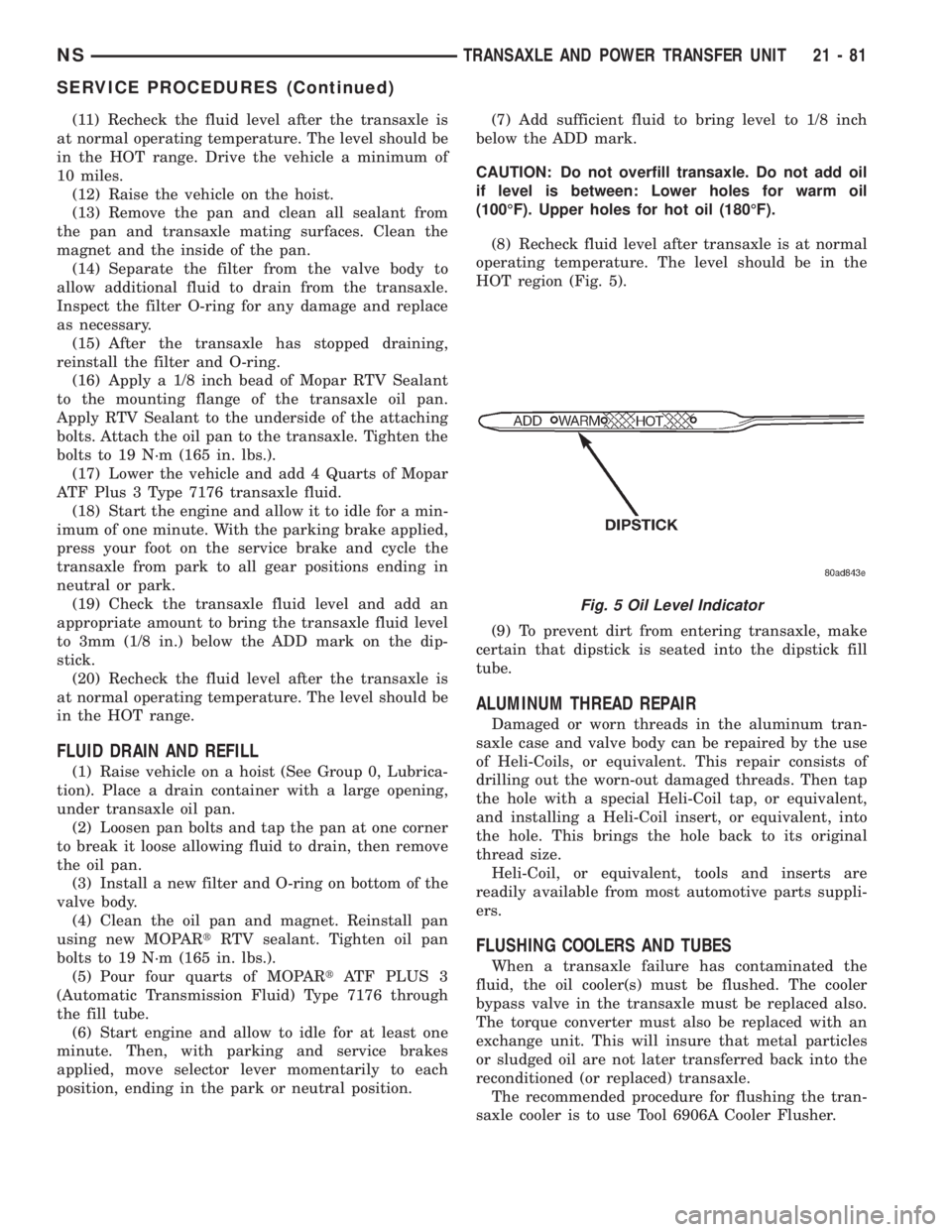
(8) Recheck fluid level after transaxle is at normal
operating temperature. The level should be in the
HOT region (Fig. 5).
(9) To prevent dirt from entering transaxle, make
certain that dipstick is seated into the dipstick fill
tube.
ALUMINUM THREAD REPAIR
Damaged or worn threads in the aluminum tran-
saxle case and valve body can be repaired by the use
of Heli-Coils, or equivalent. This repair consists of
drilling out the worn-out damaged threads. Then tap
the hole with a special Heli-Coil tap, or equivalent,
and installing a Heli-Coil insert, or equivalent, into
the hole. This brings the hole back to its original
thread size.
Heli-Coil, or equivalent, tools and inserts are
readily available from most automotive parts suppli-
ers.
FLUSHING COOLERS AND TUBES
When a transaxle failure has contaminated the
fluid, the oil cooler(s) must be flushed. The cooler
bypass valve in the transaxle must be replaced also.
The torque converter must also be replaced with an
exchange unit. This will insure that metal particles
or sludged oil are not later transferred back into the
reconditioned (or replaced) transaxle.
The recommended procedure for flushing the tran-
saxle cooler is to use Tool 6906A Cooler Flusher.
Fig. 5 Oil Level Indicator
NSTRANSAXLE AND POWER TRANSFER UNIT 21 - 81
SERVICE PROCEDURES (Continued)
Page 1556 of 1938
WARNING: WEAR PROTECTIVE EYEWEAR THAT
MEETS THE REQUIREMENTS OF OSHA AND ANSI
Z87.1±1968. WEAR STANDARD INDUSTRIAL RUB-
BER GLOVES.
KEEP LIGHTED CIGARETTES, SPARKS, FLAMES,
AND OTHER IGNITION SOURCES AWAY FROM THE
AREA TO PREVENT THE IGNITION OF COMBUSTI-
BLE LIQUIDS AND GASES. KEEP A CLASS (B) FIRE
EXTINGUISHER IN THE AREA WHERE THE
FLUSHER WILL BE USED.
KEEP THE AREA WELL VENTILATED.
DO NOT LET FLUSHING SOLVENT COME IN CON-
TACT WITH YOUR EYES OR SKIN: IF EYE CONTAM-
INATION OCCURS, FLUSH EYES WITH WATER FOR
15 TO 20 SECONDS. REMOVE CONTAMINATED
CLOTHING AND WASH AFFECTED SKIN WITH
SOAP AND WATER. SEEK MEDICAL ATTENTION.
COOLER FLUSH USING TOOL 6906A
(1) Remove cover plate filler plug on Tool 6906A.
Fill reservoir 1/2 to 3/4 full of fresh flushing solution.
Flushing solvents are petroleum based solutions gen-
erally used to clean automatic transmission compo-
nents.DO NOTuse solvents containing acids, water,
gasoline, or any other corrosive liquids.
(2) Reinstall filler plug on Tool 6906A.
(3) Verify pump power switch is turned OFF. Con-
nect red alligator clip to positive (+) battery post.
Connect black (-) alligator clip to a good ground.
(4) Disconnect the cooler lines at the transmission.
NOTE: When flushing transmission cooler and
lines, ALWAYS reverse flush.
(5) Connect the BLUE pressure line to the OUT-
LET (From) cooler line.
(6) Connect the CLEAR return line to the INLET
(To) cooler line
(7) Turn pump ON for two to three minutes to
flush cooler(s) and lines. Monitor pressure readings
and clear return lines. Pressure readings should sta-
bilize below 20 psi. for vehicles equipped with a sin-
gle cooler and 30 psi. for vehicles equipped with dual
coolers. If flow is intermittent or exceeds these pres-
sures, replace cooler.
(8) Turn pump OFF.
(9) Disconnect CLEAR suction line from reservoir
at cover plate. Disconnect CLEAR return line at
cover plate, and place it in a drain pan.
(10) Turn pump ON for 30 seconds to purge flush-
ing solution from cooler and lines. Turn pump OFF.
(11) Place CLEAR suction line into a one quart
container of MopartATF PLUS 3 Type 7176 auto-
matic transmission fluid.
(12) Turn pump ON until all transmission fluid is
removed from the one quart container and lines. Thispurges any residual cleaning solvent from the trans-
mission cooler and lines. Turn pump OFF.
(13) Disconnect alligator clips from battery. Recon-
nect flusher lines to cover plate, and remove flushing
adapters from cooler lines.
OIL PUMP VOLUME CHECK
After the new or repaired transmission has been
installed, fill to the proper level with Mopar ATF
PLUS 3 (Type 7176) automatic transmission fluid.
The volume should be checked using the following
procedure:
(1) Disconnect theFrom coolerline at the trans-
mission and place a collecting container under the
disconnected line.
CAUTION: With the fluid set at the proper level,
fluid collection should not exceed (1) quart or inter-
nal damage to the transmission may occur.
(2) Run the engineat curb idle speed, with the
shift selector in neutral.
(3) If fluid flow is intermittent or it takes more
than 20 seconds to collect one quart of ATF, discon-
nect theTo Coolerline at the transaxle.
(4) Refill the transaxle to proper level and recheck
pump volume.
(5) If flow is found to be within acceptable limits,
replace the cooler. Then fill transmission to the
proper level, using Mopar ATF PLUS 3 (Type 7176)
automatic transmission fluid.
(6) If fluid flow is still found to be inadequate,
check the line pressure using the Transaxle Hydrau-
lic Pressure Test procedure.
(7) Check the cooler for debris on the external sur-
faces. Clean as necessary.
TRANSAXLE QUICK LEARN PROCEDURE
The quick learn procedure requires the use of the
DRBIII scan tool.
This program allows the electronic transaxle sys-
tem to recalibrate itself. This will provide the best
possible transaxle operation. The quick learn proce-
dure should be performed if any of the following pro-
cedures are performed:
²Transaxle Assembly Replacement
²Transmission Control Module Replacement
²Solenoid Pack Replacement
²Clutch Plate and/or Seal Replacement
²Valve Body Replacement or Recondition
To perform the Quick Learn Procedure, the follow-
ing conditions must be met:
²The brakes must be applied
²The engine speed must be above 500 rpm
²The throttle angle (TPS) must be less than 3
degrees
21 - 82 TRANSAXLE AND POWER TRANSFER UNITNS
SERVICE PROCEDURES (Continued)
Page 1670 of 1938
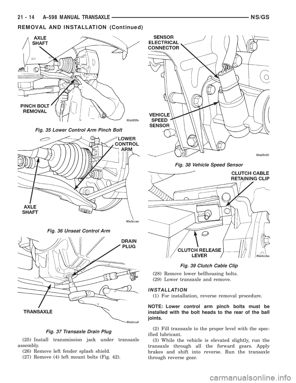
(25) Install transmission jack under transaxle
assembly.
(26) Remove left fender splash shield.
(27) Remove (4) left mount bolts (Fig. 42).(28) Remove lower bellhousing bolts.
(29) Lower transaxle and remove.
INSTALLATION
(1) For installation, reverse removal procedure.
NOTE: Lower control arm pinch bolts must be
installed with the bolt heads to the rear of the ball
joints.
(2) Fill transaxle to the proper level with the spec-
ified lubricant.
(3) While the vehicle is elevated slightly, run the
transaxle through all the forward gears. Apply
brakes and shift into reverse. Run the transaxle
through reverse gear.
Fig. 35 Lower Control Arm Pinch Bolt
Fig. 36 Unseat Control Arm
Fig. 37 Transaxle Drain Plug
Fig. 38 Vehicle Speed Sensor
Fig. 39 Clutch Cable Clip
21 - 14 A±598 MANUAL TRANSAXLENS/GS
REMOVAL AND INSTALLATION (Continued)
Page 1676 of 1938
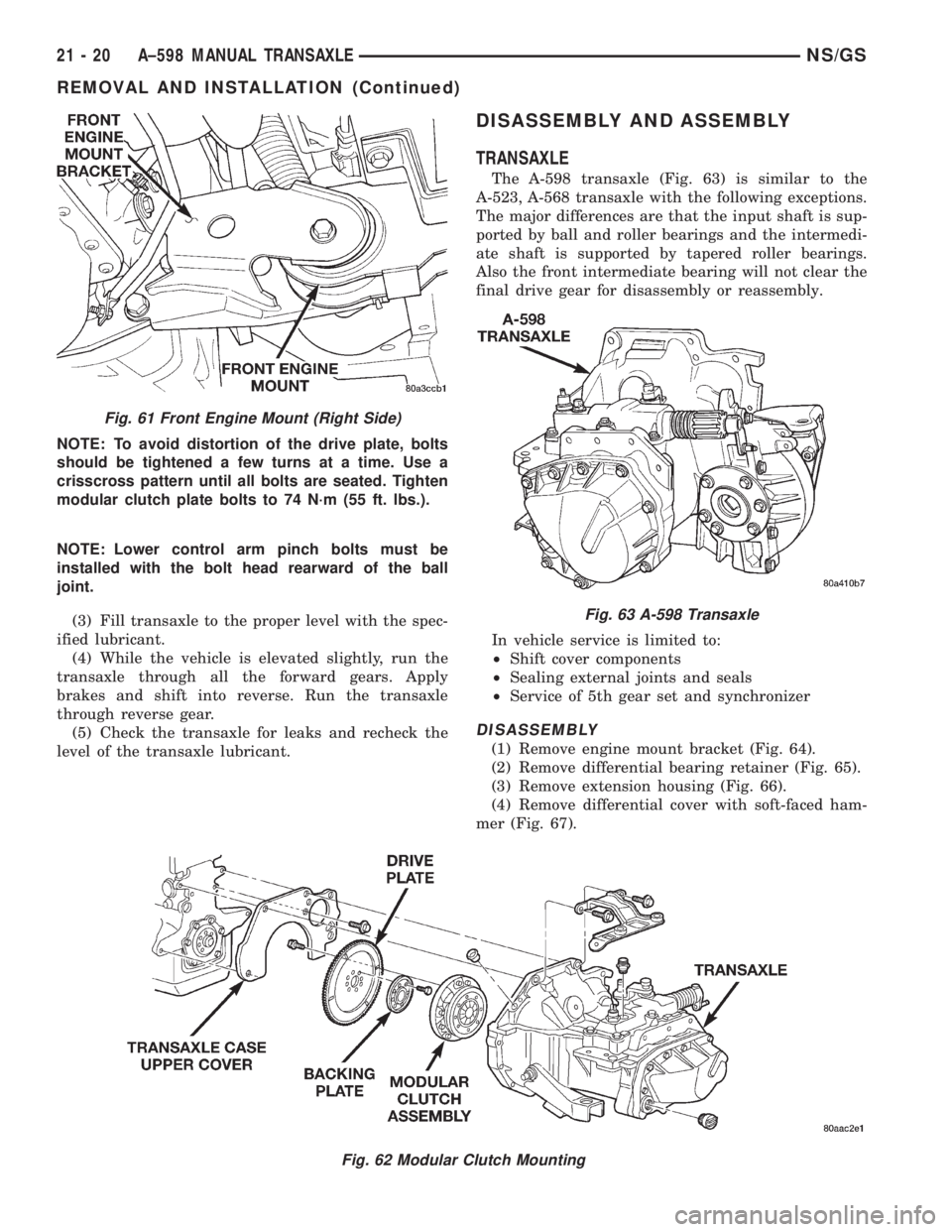
NOTE: To avoid distortion of the drive plate, bolts
should be tightened a few turns at a time. Use a
crisscross pattern until all bolts are seated. Tighten
modular clutch plate bolts to 74 N´m (55 ft. lbs.).
NOTE: Lower control arm pinch bolts must be
installed with the bolt head rearward of the ball
joint.
(3) Fill transaxle to the proper level with the spec-
ified lubricant.
(4) While the vehicle is elevated slightly, run the
transaxle through all the forward gears. Apply
brakes and shift into reverse. Run the transaxle
through reverse gear.
(5) Check the transaxle for leaks and recheck the
level of the transaxle lubricant.
DISASSEMBLY AND ASSEMBLY
TRANSAXLE
The A-598 transaxle (Fig. 63) is similar to the
A-523, A-568 transaxle with the following exceptions.
The major differences are that the input shaft is sup-
ported by ball and roller bearings and the intermedi-
ate shaft is supported by tapered roller bearings.
Also the front intermediate bearing will not clear the
final drive gear for disassembly or reassembly.
In vehicle service is limited to:
²Shift cover components
²Sealing external joints and seals
²Service of 5th gear set and synchronizer
DISASSEMBLY
(1) Remove engine mount bracket (Fig. 64).
(2) Remove differential bearing retainer (Fig. 65).
(3) Remove extension housing (Fig. 66).
(4) Remove differential cover with soft-faced ham-
mer (Fig. 67).
Fig. 62 Modular Clutch Mounting
Fig. 61 Front Engine Mount (Right Side)
Fig. 63 A-598 Transaxle
21 - 20 A±598 MANUAL TRANSAXLENS/GS
REMOVAL AND INSTALLATION (Continued)
Page 1719 of 1938

TIRES AND WHEELS
CONTENTS
page page
TIRES.................................. 1WHEELS................................ 9
TIRES
INDEX
page page
DESCRIPTION AND OPERATION
RADIAL-PLY TIRES....................... 2
REPLACEMENT TIRES.................... 3
SPARE TIRE (TEMPORARY)................ 2
TIRE INFLATION PRESSURES.............. 2
TIRE INFORMATION...................... 1
TIRE PRESSURE FOR HIGH-SPEED DRIVING . . 3
DIAGNOSIS AND TESTING
LEAD CORRECTION CHART................ 4
PRESSURE GAUGES..................... 3
TIRE NOISE OR VIBRATION................ 4TIRE WEAR PATTERNS.................... 4
TREAD WEAR INDICATORS................ 3
SERVICE PROCEDURES
REPAIRING TIRE LEAKS................... 6
TIRE AND WHEEL MATCH MOUNTING........ 6
TIRE AND WHEEL ROTATION (NON-
DIRECTIONAL THREAD PATTERN).......... 6
CLEANING AND INSPECTION
CLEANING TIRES........................ 7
SPECIFICATIONS
TIRE SPECIFICATIONS.................... 8
DESCRIPTION AND OPERATION
TIRE INFORMATION
Tires are designed and engineered for each specific
vehicle. They provide the best overall performance
for normal operation. The ride and handling charac-
teristics match the vehicle's requirements. With
proper care they will give excellent reliability, trac-
tion, skid resistance, and tread life.
Driving habits have more effect on tire life than
any other factor. Careful drivers will obtain, in most
cases, much greater mileage than severe use or care-
less drivers. A few of the driving habits which will
shorten the life of any tire are:
²Rapid acceleration
²Severe application of brakes
²High-speed driving
²Taking turns at excessive speeds
²Striking curbs and other obstacles
Radial ply tires are more prone to irregular tread
wear. It is important to follow the tire rotation inter-
val shown in the section on Tire Rotation. This will
help to achieve a greater tread-life potential.
TIRE IDENTIFICATION
Tire type, size, aspect ratio and speed rating are
encoded in the letters and numbers imprinted on the
side wall of the tire. Refer to the chart to decipher
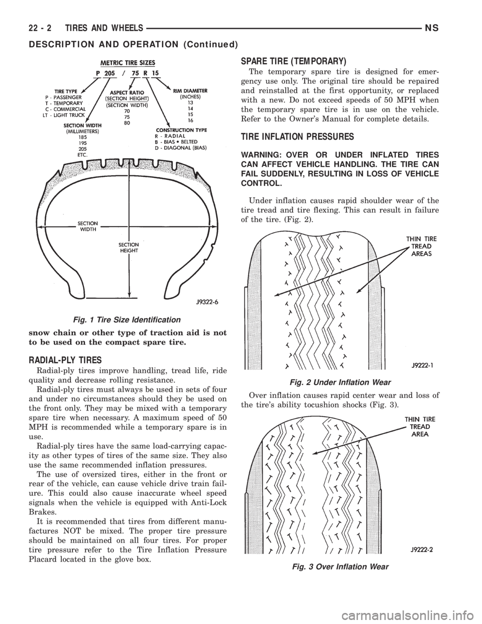
the tire identification code (Fig. 1).
Performance tires will have a speed rating letter
after the aspect ratio number. The speed rating is not
always printed on the tire sidewall. The letterSindi-
cates that the tire is speed rated up to 112 mph.
²Qup to 100 mph
²Tup to 118 mph
²Uup to 124 mph
²Hup to 130 mph
²Vup to 149 mph
²Zmore than 149 mph (consult the tire manu-
facturer for the specific speed rating)
An All Season type tire will have eitherM+S,M
&SorM±S(indicating mud and snow traction)
imprinted on the side wall.
TIRE CHAINS
This vehicle was designed to allow the use of a
specified type of snow chain on the tires. Only com-
pact snow chains or other traction aidsmeeting SAE
type ªClass Sº specifications may be used.Any style
NSTIRES AND WHEELS 22 - 1
Page 1720 of 1938
snow chain or other type of traction aid is not
to be used on the compact spare tire.
RADIAL-PLY TIRES
Radial-ply tires improve handling, tread life, ride
quality and decrease rolling resistance.
Radial-ply tires must always be used in sets of four
and under no circumstances should they be used on
the front only. They may be mixed with a temporary
spare tire when necessary. A maximum speed of 50
MPH is recommended while a temporary spare is in
use.
Radial-ply tires have the same load-carrying capac-
ity as other types of tires of the same size. They also
use the same recommended inflation pressures.
The use of oversized tires, either in the front or
rear of the vehicle, can cause vehicle drive train fail-
ure. This could also cause inaccurate wheel speed
signals when the vehicle is equipped with Anti-Lock
Brakes.
It is recommended that tires from different manu-
factures NOT be mixed. The proper tire pressure
should be maintained on all four tires. For proper
tire pressure refer to the Tire Inflation Pressure
Placard located in the glove box.
SPARE TIRE (TEMPORARY)
The temporary spare tire is designed for emer-
gency use only. The original tire should be repaired
and reinstalled at the first opportunity, or replaced
with a new. Do not exceed speeds of 50 MPH when
the temporary spare tire is in use on the vehicle.
Refer to the Owner's Manual for complete details.
TIRE INFLATION PRESSURES
WARNING: OVER OR UNDER INFLATED TIRES
CAN AFFECT VEHICLE HANDLING. THE TIRE CAN
FAIL SUDDENLY, RESULTING IN LOSS OF VEHICLE
CONTROL.
Under inflation causes rapid shoulder wear of the
tire tread and tire flexing. This can result in failure
of the tire. (Fig. 2).
Over inflation causes rapid center wear and loss of
the tire's ability tocushion shocks (Fig. 3).
Fig. 1 Tire Size Identification
Fig. 2 Under Inflation Wear
Fig. 3 Over Inflation Wear
22 - 2 TIRES AND WHEELSNS
DESCRIPTION AND OPERATION (Continued)