Page 25 of 36
Convertible Tops - 25
Group 54 31.. includes the fol-
lowing:
•Adjusting convertible top
(mechanical).
•Adjusting EM convertible top.
Group 54 31.. additionally includes the following E36 convertible top specific procedures:
•R&R complete EM Convertible Top
•Replacing rear window in convertible top
•Replacing convertible top fabric.
•R&R handle for convertible top lock
•R&R headlining in convertible top
•Replacing convertible top lid cover
•R&R base plate on left or right
Page 26 of 36
Convertible Tops - 26
Group 54 34.. includes the fol-
lowing:
•Adjusting Left/Right
Convertible top lock (fully
automatic system).
Group 54 34.. additionally includes the following E36 convertible top specific procedures:
•Initialization EM Convertible top
•Replacing linkages for convertible
•R&R electrical convertible top drive unit
•Replacing convertible top cover
•R&R finisher on convertible top lock
•R&R headlining in convertible top
•R&R both convertible top locks (fully automatic system)
•R&R motor for converter top lock (fully automatic system)
Page 27 of 36
Convertible Tops - 27
Group 61 31.. includes the fol-
lowing:
•Adjusting micro switch S4.
•Adjusting micro switch S3.
Page 28 of 36
Group 54 90.. includes trou-
bleshooting charts for the Semi
and Fully Automatic Systems with
links to repair procedures.
Group 54 90.. also includes a
micro switch logic table for diag-
nosis.
Convertible Tops - 28
Page 29 of 36

E36 CONVERTIBLE SPECIFIC SI BULLETINS
Refer to the following list of Service Information bulletins when servicing an E36 convertible.
Always check the most up-to-date SI’s and recent DCS messages for current service infor-
mation.
•E-36 CONVERTIBLE TOP HEADLINER SAGS.
Repair kit P/N 54 31 8 227 354. SIB 54 03 96.
•CONVERTIBLE TOP CLEANING KIT. P/N 83 12 9 407 806. SIB 54 07 95.
•CONVERTIBLE STORAGE LID PROTECTIVE CAP INSTALLATION. SIB 54 06 95.
•CONVERTIBLE FOLDING ASSIST ROD. P/N 54 31 8 203 869. SIB 54 05 95.
•CONVERTIBLE HEADLINER PLASTIC PANEL REPLACEMENT. P/N 54 31 8 211 902.
SIB 54 04 95.
•CONVERTIBLE TOP PLASTIC BREAKS AT C PILLAR.
Repair Kit P/N 54 31 8 209 781. SIB 54 02 95.
•CONVERTIBLE HEADLINER SAGS. SIB 54 04 94.
•CONVERTIBLE TOP FAILS WHEN LOWERING.
--Needs new drive levers-- SIB 54 03 94.
•CONVERTIBLE TOP SEAL SQUEAKS.
•CONVERTIBLE TOP ACTUATING ROD REPLACEMENT.
•CONVERTIBLE STORAGE LID LATCHING CABLES. SIB 54 06 93.
•E-36 CONVERTIBLE TOP INITIALIZATION. SIB 54 04 93.
•E-36 CONVERTIBLE GLOVE LIGHT STAYS ON. SIB 63 03 93
Convertible Tops - 29
Page 30 of 36
Convertible Tops - 30
Z3 CONVERTIBLE TOP
OVERVIEW
This Convertible top design is a single retractable mechanism that folds into a storage well
behind the seats. When stowed the top is covered by a clip on vinyl top cover. The top is
rigidly connected at the rear which eliminates the need for a tension bow as used on the
E36 top design. The top is latched to the windshield frame with catches on the left and
right sides.
The Z3 was introduced in the 1996 model year with a manual variant of the convertible top.
Starting with 4/97 production, the manual top was fitted with an additional gas spring strut
to assist the driver while raising or lowering the top. For the 1998 model year an optional
Electro Hydraulic variant also became available.
Regardless of the mode of automation, the mechanical pivot points and movement while
raising or lowering are the same for both variations.
Page 31 of 36

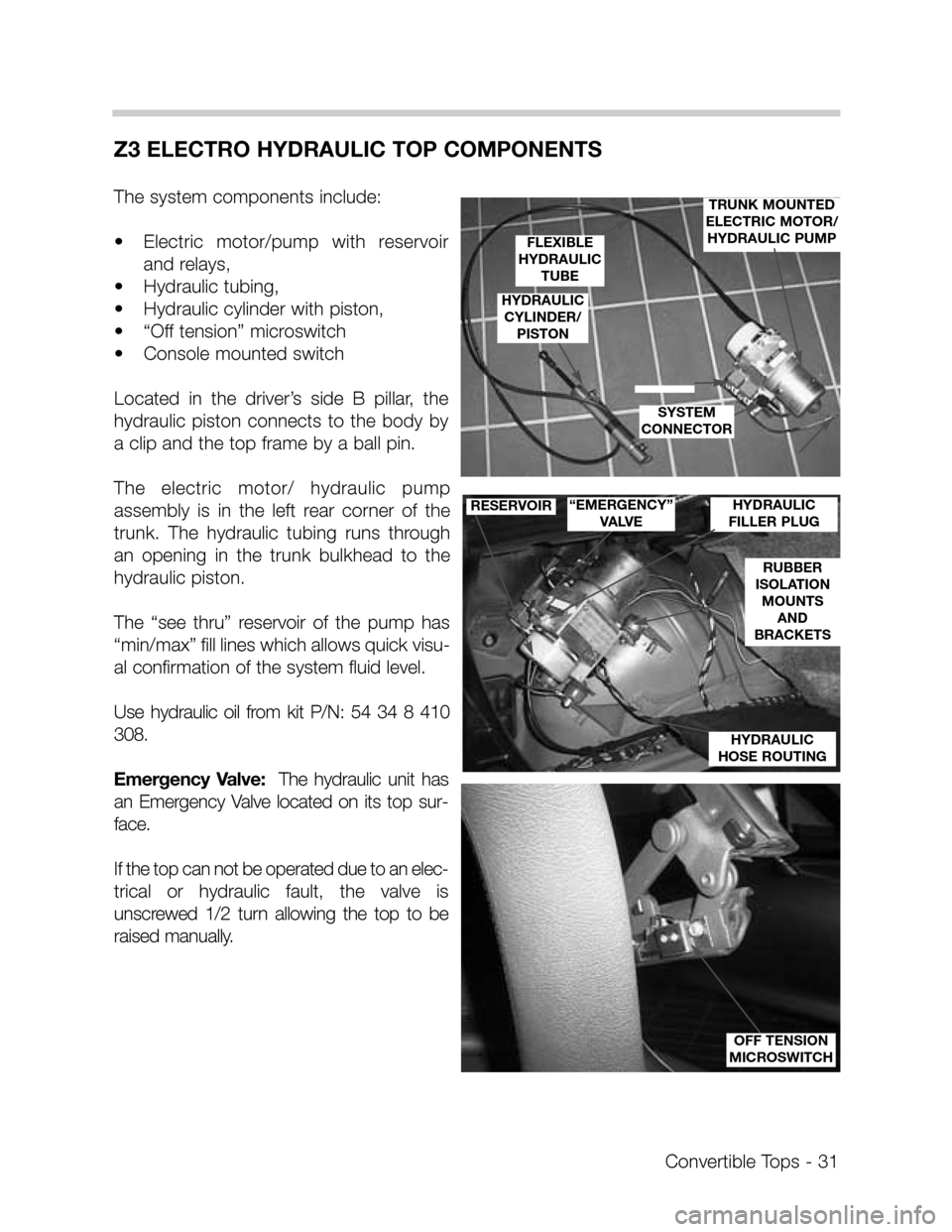
Z3 ELECTRO HYDRAULIC TOP COMPONENTS
The system components include:
•Electric motor/pump with reservoir
and relays,
•Hydraulic tubing,
•Hydraulic cylinder with piston,
•“Off tension” microswitch
•Console mounted switch
Located in the driver’s side B pillar, the
hydraulic piston connects to the body by
a clip and the top frame by a ball pin.
The electric motor/ hydraulic pump
assembly is in the left rear corner of the
trunk. The hydraulic tubing runs through
an opening in the trunk bulkhead to the
hydraulic piston.
The “see thru” reservoir of the pump has
“min/max” fill lines which allows quick visu-
al confirmation of the system fluid level.
Use hydraulic oil from kit P/N: 54 34 8 410
308.
Emergency Valve:The hydraulic unit has
an Emergency Valve located on its top sur-
face.
If the top can not be operated due to an elec-
trical or hydraulic fault, the valve is
unscrewed 1/2 turn allowing the top to be
raised manually.
Convertible Tops - 31
HYDRAULIC
FILLER PLUG
HYDRAULIC
HOSE ROUTING
RUBBER
ISOLATION
MOUNTS
AND
BRACKETS
“EMERGENCY”
VALVERESERVOIR
TRUNK MOUNTED
ELECTRIC MOTOR/
HYDRAULIC PUMP
FLEXIBLE
HYDRAULIC
TUBE
HYDRAULIC
CYLINDER/
PISTON
SYSTEM
CONNECTOR
OFF TENSION
MICROSWITCH
Page 32 of 36
Convertible Tops - 32
OPERATION
•Top operation is dependent on a stationary vehicle with the brake pedal depressed.
•Unlock the top at the windshield frame and raise past the tension point (microswitch
closes).
•With the windows lowered press the top switch in the console panel.
•The switch provides a ground for the control circuit of either the up or down relay. Power
is provided through the brake light switch circuit when the brake pedal is depressed.
•The activated relay provides operating power to the pump motor which is grounded
through the other relays not active contacts.
•Release switch once top is at end of travel.
•Motor reversal is achieved when the switch is pressed in the opposite direction activat-
ing the other relay.