Page 17 of 59
28-16
- Remove Heater Core E-box cover (arrows).
- Disconnect voltage supply relay -3-.
Pa
ge 17 of 59 I
gnition s
ystem, checkin
g
11/21/2002 htt
p://127.0.0.1:8080/audi/servlet/Dis
play?action=Goto&t
yp
e=re
pair&id=AUDI.B5.FU06.28.1
Page 18 of 59
28-17
If wire connection is OK: - Check following connection for open circuit according to wiring
diagram: 3-socket relay carrier in E-box, plenum
chamber, position 2
Terminal
Harness connector at
ignition coils
Terminal
6 1
- Repair open circuit if necessary.
- Check voltage supply of motronic Engine Control Module (ECM) power
supply relay -J271- Page 28
-18
.
- Check activation of motronic Engine Control Module (ECM) power
supply relay -J271- Page 28
-19
.
Pa
ge 18 of 59 I
gnition s
ystem, checkin
g
11/21/2002 htt
p://127.0.0.1:8080/audi/servlet/Dis
play?action=Goto&t
yp
e=re
pair&id=AUDI.B5.FU06.28.1
Page 19 of 59
28-18
Checking voltage supply
If specified value is not obtained:
Electrical Wiring Diagrams, Troubleshooting & Component Locations
If no malfunctions are found in wires: - Connect multimeter for voltage measurement as follows.3-socket relay carrier in E-box, plenum
chamber, position 2
Terminal
Measure to
2 Engine Ground
(GND)
9 Engine Ground
(GND)
Specification: approx. battery voltage
- Check wire connection between central electronics and voltage supply
relay for open circuit.
- Replace central electrics.
Pa
ge 19 of 59 I
gnition s
ystem, checkin
g
11/21/2002 htt
p://127.0.0.1:8080/audi/servlet/Dis
play?action=Goto&t
yp
e=re
pair&id=AUDI.B5.FU06.28.1
Page 20 of 59
28-19
Checking activation
If specified value is not obtained: - Connect multimeter for voltage measurement as follows.3-socket relay carrier in E-box, plenum chamber,
position 2
Terminal
Measure
to
4 B+
- Switch ignition on.
Specification: approx. battery voltage
- Switch ignition off.
- Connect VAG1598/31 test box at wiring harness to Engine Control
Module (ECM), do not connect ECM Page 24
-19
.
Pa
ge 20 of 59 I
gnition s
ystem, checkin
g
11/21/2002 htt
p://127.0.0.1:8080/audi/servlet/Dis
play?action=Goto&t
yp
e=re
pair&id=AUDI.B5.FU06.28.1
Page 21 of 59
28-20
If no malfunctions are detected: - Check following wire connection for open circuit and short circuit to
Ground (GND) and B+: Relay carrier below left cover, at bulkhead
Terminal
VAG1598/31 test box
Socket
4 21
- Repair open circuit or short circuit if necessary.
- Replace motronic Engine Control Module (ECM) power supply relay -
J271-.
Pa
ge 21 of 59 I
gnition s
ystem, checkin
g
11/21/2002 htt
p://127.0.0.1:8080/audi/servlet/Dis
play?action=Goto&t
yp
e=re
pair&id=AUDI.B5.FU06.28.1
Page 22 of 59
28-21
Intake Air Temperature (IAT) sensor -G42-,
checking
Special tools and equipment
VAG1526A
VAG1594A
VAG1598/31
VAS5051 with VAG5051/1
- or
VAG1551 with VAG1551/3A
Pa
ge 22 of 59 I
gnition s
ystem, checkin
g
11/21/2002 htt
p://127.0.0.1:8080/audi/servlet/Dis
play?action=Goto&t
yp
e=re
pair&id=AUDI.B5.FU06.28.1
Page 23 of 59
28-22
Component location Overview of component
locations Page 24
-5
Test sequence
- Connect VAS5051 tester or VAG1551 scan tool
and select control module for engine electronics
using "address word" 01 Page 01
-10
. Engine
must run at idle.
Rapid data transfer
HELP
Select function XX
When indicated on display
- Press buttons -0- and -8- to select "Read Measuring Value Block" and
press -Q- button to confirm input.
Read measurin
g value block
Q
Enter display group number XXX
When indicated on display
- Press buttons -0-, -0- and -4- to select "display group number 004" and
press -Q- button to confirm input.
Read Measuring Value Block 4
1
2
3
4
Indicated on display
- Check specified value for Intake Air Temperature (IAT) sensor in
display field 4:
Pa
ge 23 of 59 I
gnition s
ystem, checkin
g
11/21/2002 htt
p://127.0.0.1:8080/audi/servlet/Dis
play?action=Goto&t
yp
e=re
pair&id=AUDI.B5.FU06.28.1
Page 24 of 59
28-23
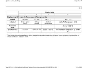
Display fields
1 2 3 4
Display group 004: Intake Air Temperature (IAT), engine at idle
Display xxxx/min xx.x volts
xxx.x C
xxx.x C
Indicated Engine speed
(RPM) Battery
voltage Coolant
temperature Intake Air Temperature (IAT)
Functional
range
-48.0 to 143.0 C
Specified value xxxx/min 12.0 to 15.0 V
80.0 to 110.0 C
From ambient temperature up to 110
C
1)
1) If a temperature is indicated which differs greatly from ambient temperature of sensor, check sensor and sensor wires for
contact resistances and open circuit.
Pa
ge 24 of 59 I
gnition s
ystem, checkin
g
11/21/2002 htt
p://127.0.0.1:8080/audi/servlet/Dis
play?action=Goto&t
yp
e=re
pair&id=AUDI.B5.FU06.28.1


.
- Disconnect voltage supply relay -3-.
Pa
ge 17 of 59 I
gnition s
ystem, checkin
g
11/21/2002 htt
p://127.0.0.1:8080/audi/servlet/Dis
pla")


 and B+: Relay carrier below left cover, at bulkhead
Terminal
V")
 sensor -G42-,
checking
Special tools and equipment
VAG1526A
VAG1594A
VAG1598/31
VAS5051 with VAG5051/1
- or
VAG1551 with VAG1551/3A
Pa
ge 22 of 59 I")

, engine at idle
Display xxxx/min xx.x volts
xxx.x C
xxx.x C
Indicated Engine speed
(RPM) B")