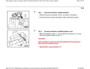
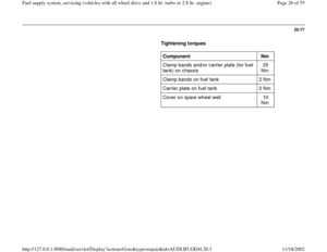
Page 49 of 55
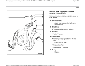
20-100
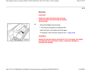
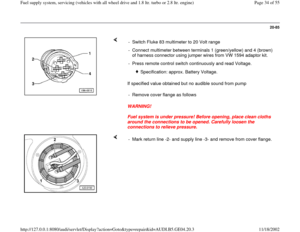
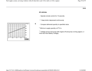
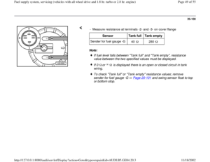
Note: - Measure resistance at terminals -2- and -3- on cover flange
Sensor
Tank full
Tank empty
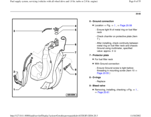
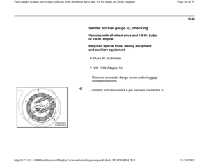
Sender for fuel gauge -G
40
280
If fuel level falls between "Tank full" and "Tank empty", resistance
value between the two specified values must be displayed. If 0 or is displayed there is an open or closed circuit in tank
wiring. To check "Tank full" or "Tank empty" resistance values; remove
sender for fuel gauge -G Page 20
-101
and swing sensor float to top
or bottom stop.
Pa
ge 49 of 55 Fuel su
pp
ly system, servicin
g (vehicles with all wheel drive and 1.8 ltr. turbo or 2.8 ltr. en
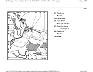
gine
)
11/18/2002 htt
p://127.0.0.1:8080/audi/servlet/Dis
play?action=Goto&t
yp
e=re
pair&id=AUDI.B5.GE04.20.3
Page 50 of 55
20-101
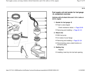
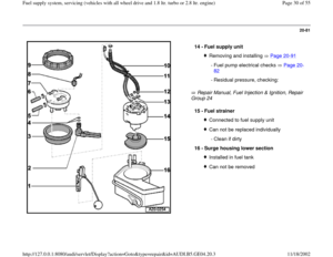
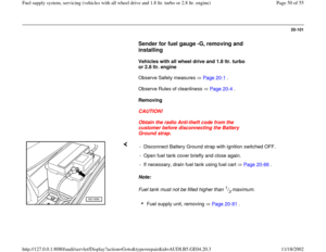
Sender for fuel gauge -G, removing and
installing
Vehicles with all wheel drive and 1.8 ltr. turbo
or 2.8 ltr. engine
Observe Safety measures Page 20
-1 .
Observe Rules of cleanliness Page 20
-4 .
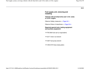
Removing
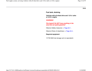
CAUTION!
Obtain the radio Anti-theft code from the
customer before disconnecting the Battery
Ground strap.
Note:
Fuel tank must not be filled higher than
1/3 maximum. - Disconnect Battery Ground strap with ignition switched OFF.
- Open fuel tank cover briefly and close again.
- If necessary, drain fuel tank using fuel cart Page 20
-66
.
Fuel supply unit, removing Page 20
-91
.
Pa
ge 50 of 55 Fuel su
pp
ly system, servicin
g (vehicles with all wheel drive and 1.8 ltr. turbo or 2.8 ltr. en
gine
)
11/18/2002 htt
p://127.0.0.1:8080/audi/servlet/Dis
play?action=Goto&t
yp
e=re
pair&id=AUDI.B5.GE04.20.3
Page 51 of 55
20-102
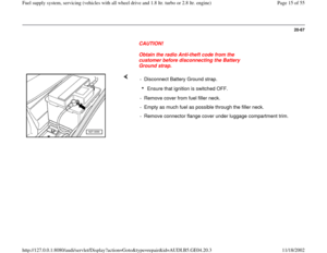
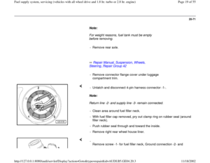
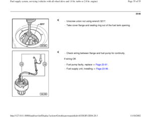
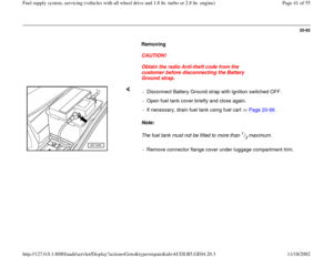
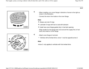
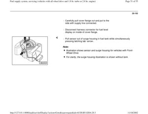
- Carefully pull cover flange out and put to the
side with supply line connected.
- Disconnect harness connector for fuel level
display on inside of cover flange.
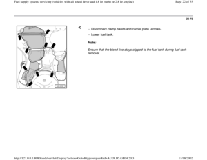
Note: - Pull sensor out of surge housing in fuel tank while simultaneously
pressing latching tab -arrow-.
Illustration shows sensor and surge housing for vehicles with Front-
Wheel Drive. For clarity, the surge housing illustration is shown without tank.
Pa
ge 51 of 55 Fuel su
pp
ly system, servicin
g (vehicles with all wheel drive and 1.8 ltr. turbo or 2.8 ltr. en
gine
)
11/18/2002 htt
p://127.0.0.1:8080/audi/servlet/Dis
play?action=Goto&t
yp
e=re
pair&id=AUDI.B5.GE04.20.3
Page 52 of 55
20-103
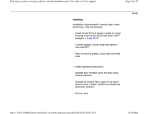
Installing
Installation is performed in reverse order, when
performing, note the following:
- Install sender for fuel gauge in guide on surge
housing outer section and press down until it
engages Page 20
-97
.
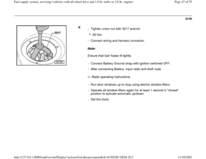
- Connect battery Ground strap with ignition
switched OFF.
- After connecting battery, input radio anti-theft
code
Radio operating instructions
- Operate door windows up to the stop using
window switches.
- Operate all window lifters again for at least 1
second in the "closed" position to activate the
automatic up/down.
- Set the clock.
Pa
ge 52 of 55 Fuel su
pp
ly system, servicin
g (vehicles with all wheel drive and 1.8 ltr. turbo or 2.8 ltr. en
gine
)
11/18/2002 htt
p://127.0.0.1:8080/audi/servlet/Dis
play?action=Goto&t
yp
e=re
pair&id=AUDI.B5.GE04.20.3
Page 53 of 55
20-104
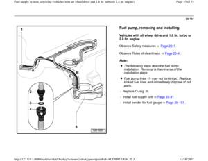
Fuel pump, removing and installing
Vehicles with all wheel drive and 1.8 ltr. turbo or
2.8 ltr. engine
Observe Safety measures Page 20
-1 .
Observe Rules of cleanliness Page 20-4 .
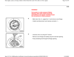
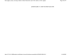
Note:
The following steps describe fuel pump
installation. Removal is the reverse of the
installation steps.
Fuel pump lines -1- may not be kinked. Replace
kinked fuel lines and immediately dispose of old
parts.
- Replace O-ring -3-.
- Install fuel supply unit Page 20
-91
.
- Install sender for fuel gauge Page 20
-101
.
Pa
ge 53 of 55 Fuel su
pp
ly system, servicin
g (vehicles with all wheel drive and 1.8 ltr. turbo or 2.8 ltr. en
gine
)
11/18/2002 htt
p://127.0.0.1:8080/audi/servlet/Dis
play?action=Goto&t
yp
e=re
pair&id=AUDI.B5.GE04.20.3
Page 54 of 55
20-105
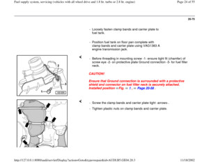
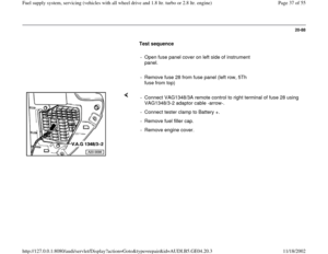
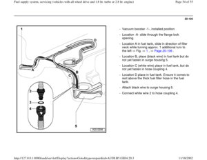
- Vacuum booster -1-, installed position
- Location -A- slide through the flange lock
opening.
- Location A in fuel tank, slide in direction of filler
neck while turning approx. 1 additional turn to
the left Fig. 1
, Page 20
-106
.
- Location B, place (black wire) in fuel tank but do
not yet fasten in surge housing 5.
- Location C (white wire) place in fuel tank, but do
not yet fasten in hose coupling 4.
- Location D place in fuel tank. Ensure it comes to
rest above the thick fuel filler hose in the fuel
tank.
- Attach black wire to surge housing 5.
- Connect white wire 2 to hose coupling 4.
Pa
ge 54 of 55 Fuel su
pp
ly system, servicin
g (vehicles with all wheel drive and 1.8 ltr. turbo or 2.8 ltr. en
gine
)
11/18/2002 htt
p://127.0.0.1:8080/audi/servlet/Dis
play?action=Goto&t
yp
e=re
pair&id=AUDI.B5.GE04.20.3
Page 55 of 55
20-106
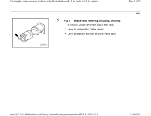
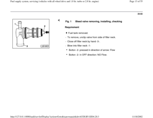
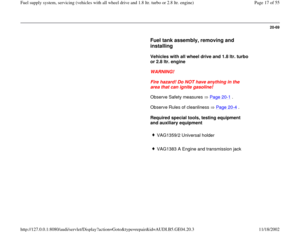
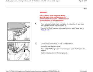
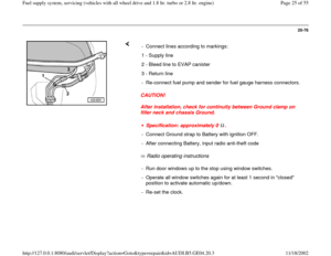
Fig. 1 Fuel pump, installing
- Turn fuel pump in direction of filler neck, into fuel tank, approx. 1 turn to
the left-arrows-.
Pa
ge 55 of 55 Fuel su
pp
ly system, servicin
g (vehicles with all wheel drive and 1.8 ltr. turbo or 2.8 ltr. en
gine
)
11/18/2002 htt
p://127.0.0.1:8080/audi/servlet/Dis
play?action=Goto&t
yp
e=re
pair&id=AUDI.B5.GE04.20.3