Page 7 of 12
01-6
VAG - On Board Dia
gnostic
HELP
1 - Rapid data transfer1)2 - Blink code output1
)
Indicated on display: 1) Appear alternately on display
Notes:
Electrical Wiring Diagrams, Troubleshooting & Component Locations If nothing is indicated on display, check diagnostic connection.
The PRINT button is used for switching on the printer. Indicator lamp
in the button comes on when printer is switched on. Depending on the program, additional operating information can be
printed out by pressing the HELP button of the VAG1551 scan tool.
Pa
ge 7 of 12 On Board Dia
gnostic
(OBD
)
11/20/2002 htt
p://127.0.0.1:8080/audi/servlet/Dis
play?action=Goto&t
yp
e=re
pair&id=AUDI.B5.SU02.01.1
Page 9 of 12

01-8
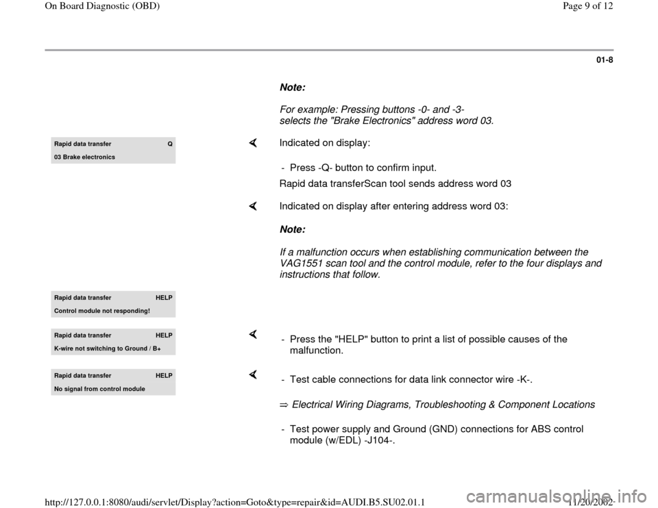
Note:
For example: Pressing buttons -0- and -3-
selects the "Brake Electronics" address word 03. Rapid data transfer
Q
03 Brake electronics
Indicated on display:
Rapid data transferScan tool sends address word 03 - Press -Q- button to confirm input.
Indicated on display after entering address word 03:
Note:
If a malfunction occurs when establishing communication between the
VAG1551 scan tool and the control module, refer to the four displays and
instructions that follow.
Rapid data transfer
HELP
Control module not respondin
g!
Rapid data transfer
HELP
K-wire not switchin
g to Ground / B+
- Press the "HELP" button to print a list of possible causes of the
malfunction.
Rapid data transfer
HELP
No si
gnal from control module
Electrical Wiring Diagrams, Troubleshooting & Component Locations - Test cable connections for data link connector wire -K-.- Test power supply and Ground (GND) connections for ABS control
module (w/EDL) -J104-.
Pa
ge 9 of 12 On Board Dia
gnostic
(OBD
)
11/20/2002 htt
p://127.0.0.1:8080/audi/servlet/Dis
play?action=Goto&t
yp
e=re
pair&id=AUDI.B5.SU02.01.1
Page 10 of 12
Electrical Wiring Diagrams, Troubleshooting & Component Locations
Pa
ge 10 of 12 On Board Dia
gnostic
(OBD
)
11/20/2002 htt
p://127.0.0.1:8080/audi/servlet/Dis
play?action=Goto&t
yp
e=re
pair&id=AUDI.B5.SU02.01.1
Page 11 of 12
01-9
Rapid data transfer
HELP
Error in communication link
If displayed:
Electrical Wiring Diagrams, Troubleshooting & Component Locations - Repair the malfunction. - After repairing the malfunction, once again enter "Brake Electronics"
address word 03 and press -Q- button to confirm.
Pa
ge 11 of 12 On Board Dia
gnostic
(OBD
)
11/20/2002 htt
p://127.0.0.1:8080/audi/servlet/Dis
play?action=Goto&t
yp
e=re
pair&id=AUDI.B5.SU02.01.1
Page 12 of 12

01-10
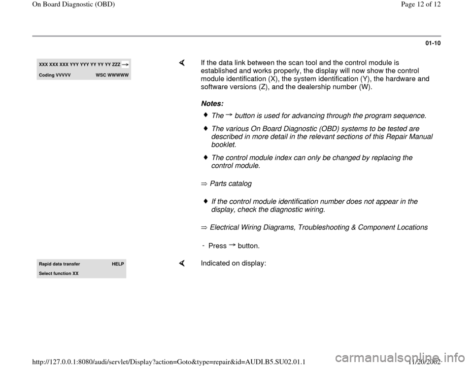
XXX XXX XXX
YYY YYY YY YY YY
ZZZ
Codin
g VVVVV
WSC WWWWW
If the data link between the scan tool and the control module is
established and works properly, the display will now show the control
module identification (X), the system identification (Y), the hardware and
software versions (Z), and the dealership number (W).
Notes:
Parts catalog
Electrical Wiring Diagrams, Troubleshooting & Component Locations
The button is used for advancing through the program sequence.The various On Board Diagnostic (OBD) systems to be tested are
described in more detail in the relevant sections of this Repair Manual
booklet. The control module index can only be changed by replacing the
control module. If the control module identification number does not appear in the
display, check the diagnostic wiring.
-
Press button.
Rapid data transfer
HELP
Select function XX
Indicated on display:
Pa
ge 12 of 12 On Board Dia
gnostic
(OBD
)
11/20/2002 htt
p://127.0.0.1:8080/audi/servlet/Dis
play?action=Goto&t
yp
e=re
pair&id=AUDI.B5.SU02.01.1