Page 25 of 41
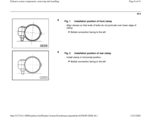
26-25
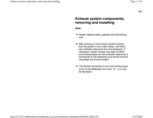
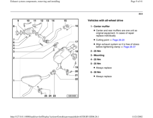
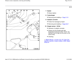
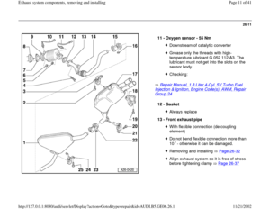
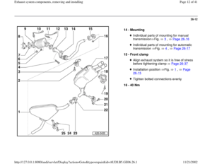
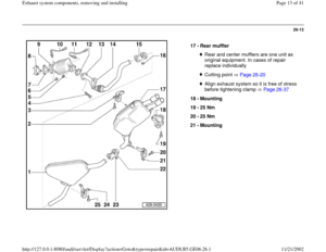
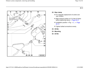
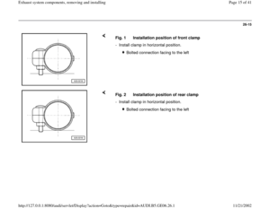
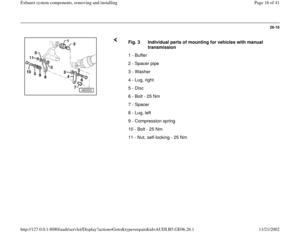
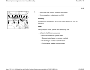
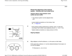
Installing
Installation is carried out in the reverse order of removal; note the
following:
Note:
Always replace seals, gaskets and self-locking nuts. - Remove all nuts -arrows- on exhaust manifold.
- Remove washers and exhaust manifold.
- Adhere to the following sequence:
Exhaust manifold to cylinder head
Exhaust turbocharger on exhaust manifold
Turbocharger bracket to cylinder block
Turbocharger bracket to turbocharger
Pa
ge 25 of 41 Exhaust s
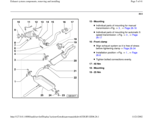
ystem com
ponents, removin
g and installin
g
11/21/2002 htt
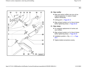
p://127.0.0.1:8080/audi/servlet/Dis
play?action=Goto&t
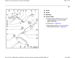
yp
e=re
pair&id=AUDI.B5.GE06.26.1
Page 26 of 41
26-26
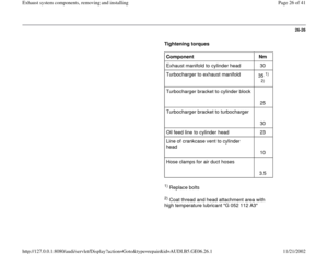
Tightening torques
Component
Nm
Exhaust manifold to cylinder head 30
Turbocharger to exhaust manifold
35
1)
2)
Turbocharger bracket to cylinder block
25
Turbocharger bracket to turbocharger
30
Oil feed line to cylinder head 23
Line of crankcase vent to cylinder
head
10
Hose clamps for air duct hoses
3.5
1) Replace bolts
2) Coat thread and head attachment area with
high temperature lubricant "G 052 112 A3"
Pa
ge 26 of 41 Exhaust s
ystem com
ponents, removin
g and installin
g
11/21/2002 htt
p://127.0.0.1:8080/audi/servlet/Dis
play?action=Goto&t
yp
e=re
pair&id=AUDI.B5.GE06.26.1
Page 27 of 41
26-27
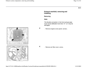
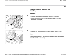
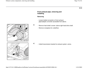
Catalytic converter, removing and
installing
Removing
- Remove heat shield -arrows- above right-hand drive shaft.
- Loosen bolted connection front exhaust pipe/catalytic converter
accessible from below.
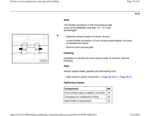
Note:
The flexible connection in the front exhaust pipe must not be deflected
more than 10 to avoid damage. - Remove bolt for transmission bracket to exhaust system -arrow-.
Pa
ge 27 of 41 Exhaust s
ystem com
ponents, removin
g and installin
g
11/21/2002 htt
p://127.0.0.1:8080/audi/servlet/Dis
play?action=Goto&t
yp
e=re
pair&id=AUDI.B5.GE06.26.1
Page 28 of 41
26-28
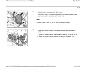
Note:
Coolant hoses -1- and -3- do not have to be disconnected. - Unbolt coolant expansion tank -2-, -arrows-.
- Disconnect wire to Engine Coolant level (ECL) Warning switch -F66-
and move coolant expansion tank to one side.
- Disconnect wiring connector for oxygen sensors and move wiring
aside.
1 - (brown) to oxygen sensor downstream of catalytic converter -G130-
2 - (black) to oxygen sensor upstream of catalytic converter -G39-
Pa
ge 28 of 41 Exhaust s
ystem com
ponents, removin
g and installin
g
11/21/2002 htt
p://127.0.0.1:8080/audi/servlet/Dis
play?action=Goto&t
yp
e=re
pair&id=AUDI.B5.GE06.26.1
Page 29 of 41
26-29
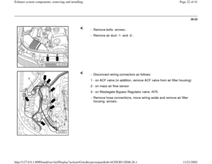
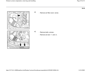
- Remove air filter cover -arrow-.
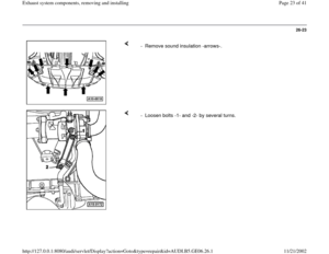
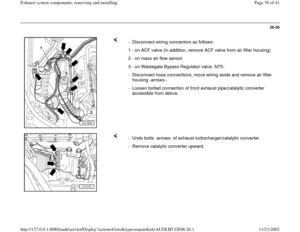
- Remove bolts -arrows-.
- Remove air duct -1- and -2-.
Pa
ge 29 of 41 Exhaust s
ystem com
ponents, removin
g and installin
g
11/21/2002 htt
p://127.0.0.1:8080/audi/servlet/Dis
play?action=Goto&t
yp
e=re
pair&id=AUDI.B5.GE06.26.1
Page 30 of 41
26-30
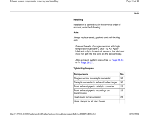
- Disconnect wiring connectors as follows:
1 - on ACF valve (in addition, remove ACF valve from air filter housing)
2 - on mass air flow sensor
3 - on Wastegate Bypass Regulator valve -N75-
- Disconnect hose connections, move wiring aside and remove air filter
housing -arrows-.
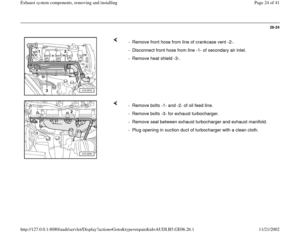
- Loosen bolted connection of front exhaust pipe/catalytic converter
accessible from above.
- Undo bolts -arrows- of exhaust turbocharger/catalytic converter.
- Remove catalytic converter upward.
Pa
ge 30 of 41 Exhaust s
ystem com
ponents, removin
g and installin
g
11/21/2002 htt
p://127.0.0.1:8080/audi/servlet/Dis
play?action=Goto&t
yp
e=re
pair&id=AUDI.B5.GE06.26.1
Page 31 of 41
26-31
Installing
Installation is carried out in the reverse order of
removal; note the following:
Note:
Always replace seals, gaskets and self-locking
nuts.
- Grease threads of oxygen sensors with high
temperature lubricant G 052 112 A3. Apply
lubricant only to threads of sensors; the lubricant
must not get into the slots on the sensor body.
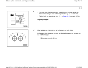
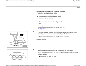
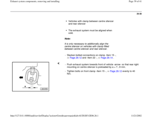
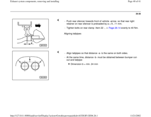
- Align exhaust system stress-free Page 26
-34
or Page 26
-37
.
Tightening torques
Components
Nm
Oxygen sensor to catalytic converter 55
Catalytic converter to exhaust turbocharger 30
Front exhaust pipe to catalytic converter 25
Front exhaust pipe to mountings on
transmission 25
Heat shield to transmission 23
Hose clamps for air duct hoses
Pa
ge 31 of 41 Exhaust s
ystem com
ponents, removin
g and installin
g
11/21/2002 htt
p://127.0.0.1:8080/audi/servlet/Dis
play?action=Goto&t
yp
e=re
pair&id=AUDI.B5.GE06.26.1
Page 32 of 41
3.5
Pa
ge 32 of 41 Exhaust s
ystem com
ponents, removin
g and installin
g
11/21/2002 htt
p://127.0.0.1:8080/audi/servlet/Dis
play?action=Goto&t
yp
e=re
pair&id=AUDI.B5.GE06.26.1


2)
Turbocharger bracket to cylinder block
25
Turboc")

 Warning switch -F66-
a")


2 - on mass air flow sensor
3 - on Wastegate Bypass Regulator valve -")

