Page 25 of 30
26-25
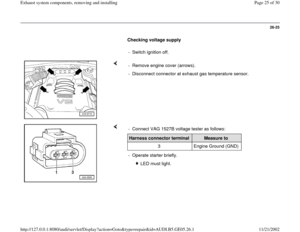
Checking voltage supply
- Switch ignition off.
- Remove engine cover (arrows).
- Disconnect connector at exhaust gas temperature sensor.
- Connect VAG 1527B voltage tester as follows:Harness connector terminal
Measure to
3 Engine Ground (GND)
- Operate starter briefly.
LED must light.
Pa
ge 25 of 30 Exhaust s
ystem com
ponents, removin
g and installin
g
11/21/2002 htt
p://127.0.0.1:8080/audi/servlet/Dis
play?action=Goto&t
yp
e=re
pair&id=AUDI.B5.GE05.26.1
Page 26 of 30
26-26
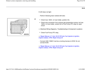
If LED does not light:
- Perform following tests marked with dots:
Electrical Wiring Diagrams, Troubleshooting & Component Locations
Repair Manual, 2.7 Liter V6 5V BiTurbo Fuel Injection & Ignition,
Engine Code(s): APB, Repair Group 24
Repair Manual, 2.7 Liter V6 5V BiTurbo Fuel Injection & Ignition,
Engine Code(s): APB, Repair Group 24
Check fuse -S234- (in fuse holder, position 34). Check wire connection from exhaust gas temperature sensor via fuse
-S234- (in fuse holder, socket 34) to Fuel Pump (FP) relay for open
circuit: Check Fuel Pump (FP) relay.
- Connect VAG 1598/31 test box at wiring harness to ECM. Do not
connect ECM.
Pa
ge 26 of 30 Exhaust s
ystem com
ponents, removin
g and installin
g
11/21/2002 htt
p://127.0.0.1:8080/audi/servlet/Dis
play?action=Goto&t
yp
e=re
pair&id=AUDI.B5.GE05.26.1
Page 27 of 30
26-27
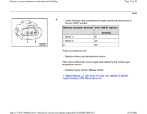
If wire connection is OK:
If the same malfunction occurs again after replacing the exhaust gas
temperature sensor:
Repair Manual, 2.7 Liter V6 5V BiTurbo Fuel Injection & Ignition, Engine Code(s): APB, Repair Group 24
- Check following wire connections for open circuit and short circuit to
Ground (GND) and B+:
Harness connector terminal
VAG 1598/31 test box
Bushing
1 (Bank 1) 61
1 (Bank 2) 20
2 50
- Replace exhaust gas temperature sensor.
- Replace Engine Control Module (ECM).
Pa
ge 27 of 30 Exhaust s
ystem com
ponents, removin
g and installin
g
11/21/2002 htt
p://127.0.0.1:8080/audi/servlet/Dis
play?action=Goto&t
yp
e=re
pair&id=AUDI.B5.GE05.26.1
Page 28 of 30
26-28
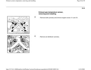
Exhaust gas temperature sensor,
removing and installing
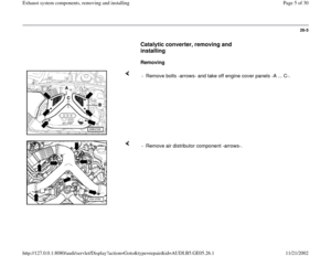
- Remove bolts (arrows) and remove engine covers -A- and -B-.
- Remove air distributor (arrows).
Pa
ge 28 of 30 Exhaust s
ystem com
ponents, removin
g and installin
g
11/21/2002 htt
p://127.0.0.1:8080/audi/servlet/Dis
play?action=Goto&t
yp
e=re
pair&id=AUDI.B5.GE05.26.1
Page 29 of 30
26-29
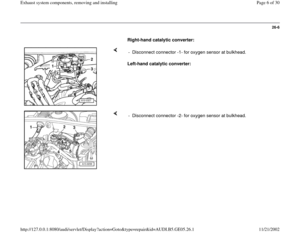
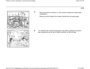
- Disconnect both connectors -2- from control modules for exhaust gas
temperature.
- Remove control module from intake manifold and set wires aside.
For vehicles with manual transmission, the control modules for exhaust
gas temperature are at rear of intake manifold, on left and right.
Pa
ge 29 of 30 Exhaust s
ystem com
ponents, removin
g and installin
g
11/21/2002 htt
p://127.0.0.1:8080/audi/servlet/Dis
play?action=Goto&t
yp
e=re
pair&id=AUDI.B5.GE05.26.1
Page 30 of 30
26-30
- Remove exhaust gas temperature sensor from exhaust manifold.
Pa
ge 30 of 30 Exhaust s
ystem com
ponents, removin
g and installin
g
11/21/2002 htt
p://127.0.0.1:8080/audi/servlet/Dis
play?action=Goto&t
yp
e=re
pair&id=AUDI.B5.GE05.26.1
.
- Disconnect connector at exhaust gas temperature sensor.
- Connect VAG 1527B voltage")


 and remove engine covers -A- and -B-.
- Remove air distributor (arrows).
Pa
ge 28 of 30 Exha")

