Page 9 of 42
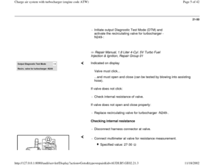
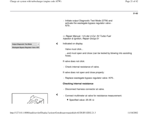
Repair Manual, 1.8 Liter 4-Cyl. 5V Turbo Fuel Injection & Ignition,
Repair Group 01 recirculating valve for turbocharger -N249-:
LED must blink.
Pa
ge 9 of 42 Char
ge air s
ystem with turbochar
ger
(en
gine code ATW
)
11/18/2002 htt
p://127.0.0.1:8080/audi/servlet/Dis
play?action=Goto&t
yp
e=re
pair&id=AUDI.B5.GE02.21.3
Page 10 of 42
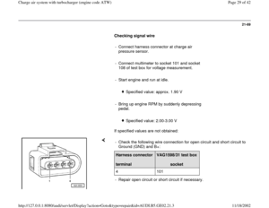
21-53
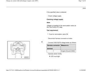
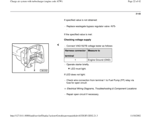
If LED does not blink or if it remains constantly
lit:
- Connect VAG1598/31 test box at wiring harness
to ECM, do not connect ECM:
Repair Manual, 1.8 Liter 4-Cyl. 5V Turbo Fuel
Injection & Ignition, Repair Group 24
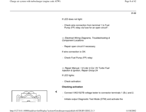
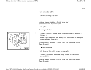
If wire connection is OK:
Repair Manual, 1.8 Liter 4-Cyl. 5V Turbo Fuel Injection & Ignition,
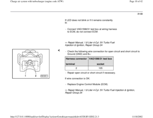
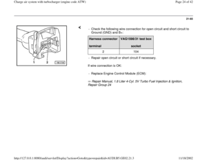
Repair Group 24 - Check the following wire connection for open circuit and short circuit to
Ground (GND) and B+: Harness connector
terminal
VAG1598/31 test box
socket
2 105
- Repair open circuit or short circuit if necessary.
- Replace Engine Control Module (ECM):
Pa
ge 10 of 42 Char
ge air s
ystem with turbochar
ger
(en
gine code ATW
)
11/18/2002 htt
p://127.0.0.1:8080/audi/servlet/Dis
play?action=Goto&t
yp
e=re
pair&id=AUDI.B5.GE02.21.3
Page 11 of 42
21-54
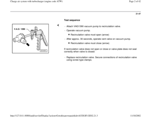
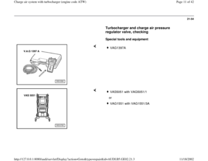
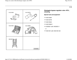
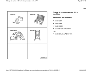
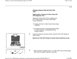
Turbocharger and charge air pressure
regulator valve, checking
Special tools and equipment
VAG1397A
VAS5051 with VAG5051/1
orVAG1551 with VAG1551/3A
Pa
ge 11 of 42 Char
ge air s
ystem with turbochar
ger
(en
gine code ATW
)
11/18/2002 htt
p://127.0.0.1:8080/audi/servlet/Dis
play?action=Goto&t
yp
e=re
pair&id=AUDI.B5.GE02.21.3
Page 12 of 42
21-55
Test requirements
All hoses and wires have been checked for
proper seating and seal.
DTC memory checked
Repair Manual, 1.8 Liter 4-Cyl. 5V Turbo Fuel
Injection & Ignition, Repair Group 01
Output Diagnostic Test Mode (DTM)
performed
Repair Manual, 1.8 Liter 4-Cyl. 5V Turbo Fuel
Injection & Ignition, Repair Group 01
Vehicle tester VAS 5051 or VAG 1551
connected.
Test sequence
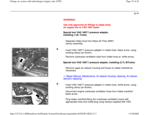
WARNING!
To reduce the risk of accident or injury while
carrying out tests and measurements during
a road test, observe safety precautions
Page 21
-40
.
Pa
ge 12 of 42 Char
ge air s
ystem with turbochar
ger
(en
gine code ATW
)
11/18/2002 htt
p://127.0.0.1:8080/audi/servlet/Dis
play?action=Goto&t
yp
e=re
pair&id=AUDI.B5.GE02.21.3
Page 13 of 42
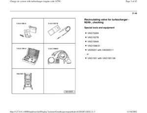
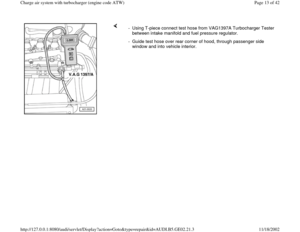
- Using T-piece connect test hose from VAG1397A Turbocharger Tester
between intake manifold and fuel pressure regulator.
- Guide test hose over rear corner of hood, through passenger side
window and into vehicle interior.
Pa
ge 13 of 42 Char
ge air s
ystem with turbochar
ger
(en
gine code ATW
)
11/18/2002 htt
p://127.0.0.1:8080/audi/servlet/Dis
play?action=Goto&t
yp
e=re
pair&id=AUDI.B5.GE02.21.3
Page 14 of 42
.
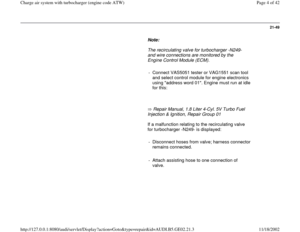
- Connect test hose to connection barb -I-.
Hoses must be properly connected and there must b")
21-56
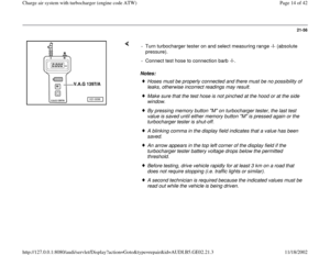
Notes: - Turn turbocharger tester on and select measuring range -I- (absolute
pressure).
- Connect test hose to connection barb -I-.
Hoses must be properly connected and there must be no possibility of
leaks, otherwise incorrect readings may result. Make sure that the test hose is not pinched at the hood or at the side
window. By pressing memory button "M" on turbocharger tester, the last test
value is saved until either memory button "M" is pressed again or the
turbocharger tester is shut-off. A blinking comma in the display field indicates that a value has been
saved. An arrow appears in the top left corner of the display field if the
turbocharger tester battery voltage drops below the permitted
threshold. Before testing, drive vehicle rapidly for at least 3 km on a road that
does not require stopping (i.e. traffic lights or similar). A second technician is required because the indicated values must be
read out while the vehicle is being driven.
Pa
ge 14 of 42 Char
ge air s
ystem with turbochar
ger
(en
gine code ATW
)
11/18/2002 htt
p://127.0.0.1:8080/audi/servlet/Dis
play?action=Goto&t
yp
e=re
pair&id=AUDI.B5.GE02.21.3
Page 15 of 42

21-57
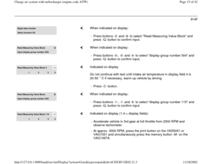
Rapid data transferSelect function XX
When indicated on display:
- Press buttons -0- and -8- to select "Read Measuring Value Block" and
press -Q- button to confirm input.
Read Measuring Value Block
Q
Input displa
y group number XXX
When indicated on display:
- Press buttons -0-, -0- and -4- to select "display group number 004" and
press -Q- button to confirm input.
Read Measuring Value Block 4
1
2
3
4
Indicated on display
Do not continue with test until intake air temperature in display field 4 is
20-50 C if necessary, warm up vehicle by driving. - Press -C- button.
Read Measuring Value Block
Q
Input displa
y group number XXX
When indicated on display:
- Press buttons -1-, -1- and -5- to select "display group number 115" and
press -Q- button to confirm input.
Read Measuring Value Block 115
1
2
3
4
Indicated on display (1-4 = display fields)
- Accelerate vehicle in 3rd gear at full throttle from 2000 RPM and
observe tachometer.
- At approx. 3000 RPM, press the print button on the VAS5051 or
VAG1551 and simultaneously press the memory button -M- on the
VAG1397A.
Pa
ge 15 of 42 Char
ge air s
ystem with turbochar
ger
(en
gine code ATW
)
11/18/2002 htt
p://127.0.0.1:8080/audi/servlet/Dis
play?action=Goto&t
yp
e=re
pair&id=AUDI.B5.GE02.21.3
Page 16 of 42
21-58
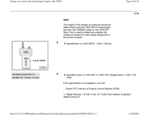
Note:
The height of the charge air pressure should be
determined using the VAG1397/A turbocharger
test tool, the VAS5051 tester or the VAG1551
Scan Tool is used to determine whether the
charge air pressure is also being recognized in
the control module.
Specification on VAG1397A: 1.450-1.700 bar
Read Measuring Value Block 115 3000 RPM
42%
1770 mbar
1770 mbar
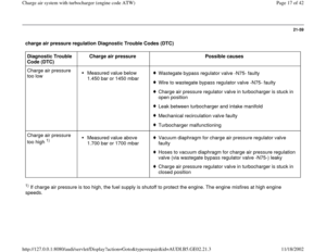
If the specification is exceeded or not met:
Repair Manual, 1.8 Liter 4-Cyl. 5V Turbo Fuel Injection & Ignition,
Repair Group 01
Specified value on VAS 5051 or VAG 1551 Display field 4: 1450-1700
mbar
- Check DTC memory of Engine Control Module (ECM):
Pa
ge 16 of 42 Char
ge air s
ystem with turbochar
ger
(en
gine code ATW
)
11/18/2002 htt
p://127.0.0.1:8080/audi/servlet/Dis
play?action=Goto&t
yp
e=re
pair&id=AUDI.B5.GE02.21.3