Page 948 of 976
ENGINE
OVERHAUL53
9.Position selected shims, spacer and drive plate
to crankshaft.
NOTE: Dowel located.
10.Fit and finger tighten 8 bolts.
NOTE: Locking plate is no longer required.
11.Restrain crankshaft using toolLRT-12-080
and tighten drive plate bolts to 146 Nm.
12.Remove toolLRT-12-080and crankshaft
pulley.FLYWHEEL/DRIVE PLATE HOUSING
Remove
1.Remove flywheel/drive plate.
NOTE: Flywheel housing illustrated.
2.Remove 2 bolts securing top of housing to
cylinder block.
3.Remove 4 bolts securing housing to engine
mountings.
4.Progressively slacken then remove 6 bolts
securing housing to cylinder block.
5.Remove housing.
Page 949 of 976
ENGINE
54
OVERHAUL Refit
1.Remove all traces of sealant from mating faces
of housing and cylinder block using solvent
from kit GUG 705548GM.
2.Apply a bead of sealant from kit to cylinder
block.
3.Position housing to cylinder block.
4.Fit and finger tighten bolts.
5.Using sequence shown, tighten bolts to 45 Nm.
NOTE: If engine mounting bolts were not
fitted, omit bolts 8, 10, 11 and 12 from
tightening sequence and re-number
accordingly.
6.Fit flywheel/drive plate.
Page 950 of 976
ENGINE
OVERHAUL55
CRANKSHAFT, CAMSHAFT, PISTONS AND
CYLINDER BLOCK
1.Remove timing belt rear cover.
2.Remove flywheel/drive plate housing.
3.Remove fuel lift pump.
4.Remove cylinder head.
5.Remove sump, oil pick-up and drain pipes.
6.Remove oil filter head.
7.Remove brake servo vacuum pump.Crankshaft rear oil seal - remove
1.Remove 5 bolts securing rear oil seal housing
to cylinder block.
2.Remove and discard oil seal and housing.
3.
Early engines:Remove and discard 'O' ring.
4.Remove and discard gasket.
Page 954 of 976

ENGINE
OVERHAUL59
Crankshaft - regrinding
NOTE: Crankshaft journals may be
reground to the following dimensions.
Main bearing journals = 63.225 to 63.237 mm
Big-end bearing journals = 58.475 to 58.494 mm
CAUTION: Rotation of crankshaft must be
in an ANTI-CLOCKWISE direction when
viewed from flywheel end of crankshaft.
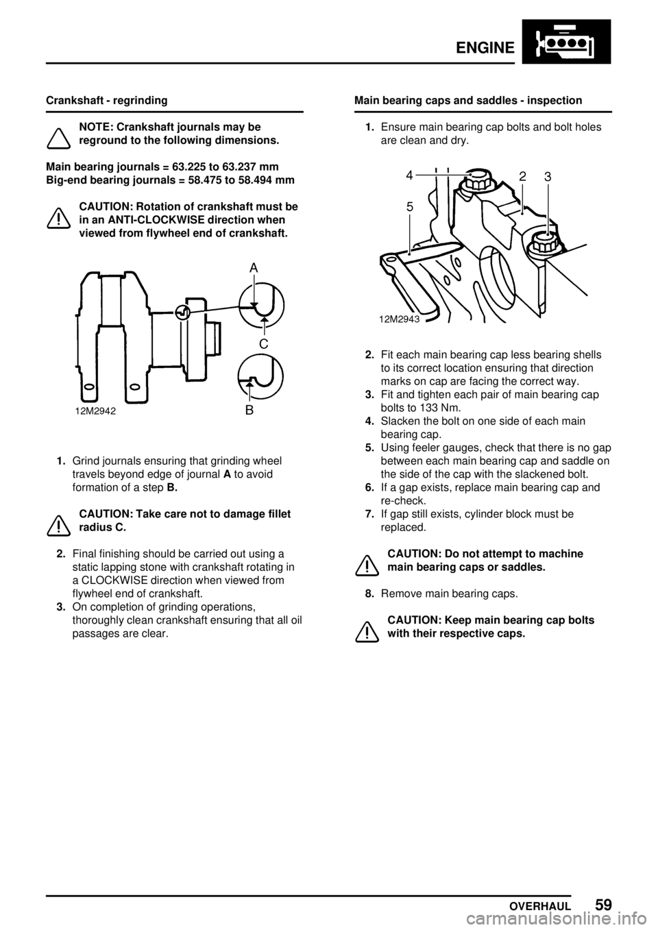
1.Grind journals ensuring that grinding wheel
travels beyond edge of journalAto avoid
formation of a stepB.
CAUTION: Take care not to damage fillet
radius C.
2.Final finishing should be carried out using a
static lapping stone with crankshaft rotating in
a CLOCKWISE direction when viewed from
flywheel end of crankshaft.
3.On completion of grinding operations,
thoroughly clean crankshaft ensuring that all oil
passages are clear.Main bearing caps and saddles - inspection
1.Ensure main bearing cap bolts and bolt holes
are clean and dry.
2.Fit each main bearing cap less bearing shells
to its correct location ensuring that direction
marks on cap are facing the correct way.
3.Fit and tighten each pair of main bearing cap
bolts to 133 Nm.
4.Slacken the bolt on one side of each main
bearing cap.
5.Using feeler gauges, check that there is no gap
between each main bearing cap and saddle on
the side of the cap with the slackened bolt.
6.If a gap exists, replace main bearing cap and
re-check.
7.If gap still exists, cylinder block must be
replaced.
CAUTION: Do not attempt to machine
main bearing caps or saddles.
8.Remove main bearing caps.
CAUTION: Keep main bearing cap bolts
with their respective caps.
Page 975 of 976

ENGINE
DATA, TORQUE & TOOLS3
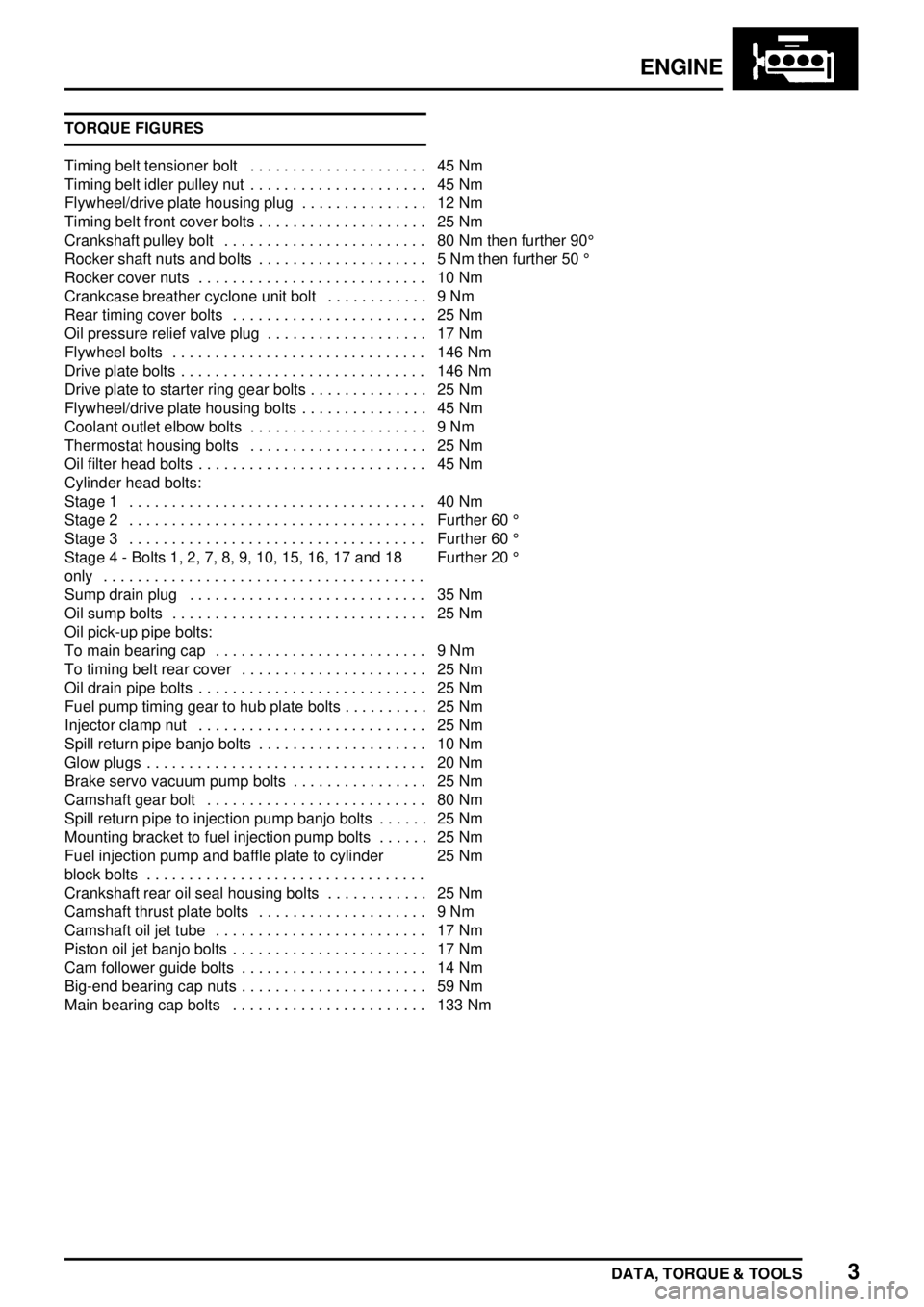
TORQUE FIGURES
Timing belt tensioner bolt 45 Nm.....................
Timing belt idler pulley nut 45 Nm.....................
Flywheel/drive plate housing plug 12 Nm...............
Timing belt front cover bolts 25 Nm....................
Crankshaft pulley bolt 80 Nm then further 90° ........................
Rocker shaft nuts and bolts 5 Nm then further 50° ....................
Rocker cover nuts 10 Nm...........................
Crankcase breather cyclone unit bolt 9 Nm............
Rear timing cover bolts 25 Nm.......................
Oil pressure relief valve plug 17 Nm...................
Flywheel bolts 146 Nm..............................
Drive plate bolts 146 Nm.............................
Drive plate to starter ring gear bolts 25 Nm..............
Flywheel/drive plate housing bolts 45 Nm...............
Coolant outlet elbow bolts 9 Nm.....................
Thermostat housing bolts 25 Nm.....................
Oil filter head bolts 45 Nm...........................
Cylinder head bolts:
Stage 1 40 Nm...................................
Stage 2 Further 60° ...................................
Stage 3 Further 60° ...................................
Stage 4 - Bolts 1, 2, 7, 8, 9, 10, 15, 16, 17 and 18
onlyFurther 20°
......................................
Sump drain plug 35 Nm............................
Oil sump bolts 25 Nm..............................
Oil pick-up pipe bolts:
To main bearing cap 9 Nm.........................
To timing belt rear cover 25 Nm......................
Oil drain pipe bolts 25 Nm...........................
Fuel pump timing gear to hub plate bolts 25 Nm..........
Injector clamp nut 25 Nm...........................
Spill return pipe banjo bolts 10 Nm....................
Glow plugs 20 Nm.................................
Brake servo vacuum pump bolts 25 Nm................
Camshaft gear bolt 80 Nm..........................
Spill return pipe to injection pump banjo bolts 25 Nm......
Mounting bracket to fuel injection pump bolts 25 Nm......
Fuel injection pump and baffle plate to cylinder
block bolts25 Nm
.................................
Crankshaft rear oil seal housing bolts 25 Nm............
Camshaft thrust plate bolts 9 Nm....................
Camshaft oil jet tube 17 Nm.........................
Piston oil jet banjo bolts 17 Nm.......................
Cam follower guide bolts 14 Nm......................
Big-end bearing cap nuts 59 Nm......................
Main bearing cap bolts 133 Nm.......................