1995 LAND ROVER DISCOVERY differential
[x] Cancel search: differentialPage 443 of 976
44AUTOMATIC GEARBOX
6
REPAIR 13.Remove starter.
14.Working through starter aperture note position of
torque converter flexible drive plate to facilitate
refitting.
15.Remove the four torque convertor to flexible
drive securing bolts, rotating engine to gain
access to each individual bolt.
16.Raise vehicle on four post ramp [hoist].
17.Drain lubrication oil from transfer and main
gearboxes.
18.Disconnect speedometer cable from transfer
gearbox and disconnect associated clipping.
19.Remove rear propeller shaft.
See PROPELLER
SHAFTS, Overhaul, Flexible Coupling
20.Disconnect front propeller shaft at transfer
gearbox and tie to one side.
21.Remove exhaust front pipe.
22.Remove bolts securing front and centre silencer
mounting brackets and tie silencer to one side.
23.Disconnect oil cooler pipes from gearbox.
24.Blank off pipes and union connections.
25.Remove bolt securing retaining bracket to sump
and move cooler pipes aside.
26.Disconnect selector cable from lever on side of
gearbox.
27.Disconnect inhibitor switch multi-plug.
28.Disconnect park brake cable from linkage to park
brake lever.
29.Disconnect electrical connections from
differential lock switch on transfer gearbox.
30.Remove two lower bolts from transfer gearbox
input bearing support plate.
31.Assemble approved support cradle to
transmission hoist.32.Raise hoist and secure cradle to transfer
gearbox input bearing support plate using bolts
removed.
33.Disconnect gearbox mounting brackets from
chassis cross member.
34.Remove chassis cross member.
35.Lower transmission sufficiently to allow access
to items attached to top of gearbox.
36.Remove left hand gearbox mounting bracket
assembly.
37.Remove ties from breather pipes and harness.
38.Remove nut securing gearbox oil filler/dip stick
tube to bell housing.
39.Release union nut at gearbox sump and remove
filler/dipstick tube. Fit blanking plugs.
40.Support engine using a wooden block with a
suitable ramp [hoist] jack.
41.Remove nut securing kick down cable bracket to
bell housing.
42.Remove two bolts securing top of bell housing to
flywheel housing.
43.Remove nuts securing bell housing to flywheel
housing and withdraw transmission assembly
from engine.
44.Fit a suitable torque converter retaining strap to
the bell housing.
45.Remove hoist and transmission from under
vehicle.
46.Fit lifting eyes to transmission.
47.Using suitable chains and lifting tackle take
weight of transmission assembly.
48.Remove bolts securing transmission cradle to
transfer box and withdraw hoist complete with
cradle.
49.Refit bolts to cover plate.
Page 444 of 976
ZF
7
REPAIR Accessories removal/fitting
If fitting a replacement transmission assembly to the
vehicle, remove the following items from the existing
assembly and fit to the replacement.
CAUTION: It is important to remove the
spacer from the extension shaft and fit
onto the replacement unit.
50.Breather pipe union and washers from main
gearbox.
51.Breather pipe, union and washers from transfer
gearbox.
52.Main gearbox selector lever.
53.RH mounting bracket assembly.
54.Oil cooler pipe unions.
55.Fit blanks to all apertures where unions have
been removed and blank off pipe ends.
Refit
1.Fit transmission to cradle and hoist.
2.Locate hoist under vehicle and remove torque
convertor retaining strap.
3.Ensure low range gear is engaged.
4.Apply approved sealant to bell housing face.
5.Carefully raise assembly, align bell housing with
flywheel housing and bring mating faces
together.
6.Fit nuts and bolts to secure transmission to
engine.
7.Locate electrical wiring and breather pipes to
position.
8.Secure kick down cable clip to bell housing.
9.Raise hoist sufficiently to take weight.
10.Remove block and jack from engine sump.
11.Fit filler/dipstick tube to gearbox sump and
secure bracket to bell housing.
12.Apply Loctite to torque convertor bolts
13.Working through starter aperture refit the four
torque convertor to flexible drive securing bolts,
rotating crankshaft to gain access to bolt
locations.
14.Refit starter and heatshield.
15.Secure breather pipes and harness with ties.
16.Fit left hand mounting bracket assembly to
gearbox.
17.Raise transmission and support with a suitable
ramp [hoist] jack.
18.Remove two bolts securing transmission to
cradle, lower hoist and remove from under
vehicle.
19.Apply Loctite to above bolts and fit to transfer
gearbox input bearing support plate.
20.Fit chassis cross member.21.Secure gearbox mounting brackets to chassis
cross member.
22.Remove ramp [hoist] jack.
23.Connect electrical leads to differential lock
switch.
24.Connect inhibitor switch multi-plug.
25.Connect selector cable to lever on side of
gearbox.
26.Connect oil cooler pipes to gearbox and secure
retaining bracket to gearbox sump.
27.Secure silencer to chassis and refit exhaust front
pipe.
28.Refit front propeller shaft to transfer gearbox.
29.Refit rear propeller shaft.
See PROPELLER
SHAFTS, Overhaul, Flexible Coupling
30.Connect speedometer cable to transfer gearbox.
31.Refill transfer gearbox with correct grade of
lubricating oil.
See LUBRICANTS, FLUIDS
AND CAPACITIES, Information,
Recommended Lubricants and Fluids
32.Lower ramp [hoist] to ground level.
33.Reconnect turbo-charger hose to inter-cooler.
34.Reconnect top hose to radiator.
35.Refill cooling system with correct mixture of
coolant.
See LUBRICANTS, FLUIDS AND
CAPACITIES, Information, Recommended
Lubricants and Fluids
36.Reconnect kick down cable to fuel injection
pump.
37.Secure breather pipe clip to rear of cylinder
head.
38.Engage harness with clips along top of
bulkhead.
39.On left hand drive vehicles only, connect
multi-plug to top of brake fluid reservoir.
40.Refit insulation pad to rocker cover and inlet
manifold, secure with oil filler cap.
41.Refit gaiter and knob to transfer gear lever.
42.Select high range gear.
43.Reconnect battery terminals.
44.Refill main gearbox with correct grade of
lubricating oil.
See LUBRICANTS, FLUIDS
AND CAPACITIES, Information,
Recommended Lubricants and Fluids
Page 467 of 976
PROPELLER SHAFTS
1
DESCRIPTION AND OPERATION PROPELLER SHAFT ALIGNMENT
Description
The front and rear propeller shafts have non-constant
velocity 'Hooks' type universal joints, with needle roller
bearings. The bearing cups are pre-packed with
lubricant on assembly and a grease nipple is fitted for
servicing as specified, in maintenance section.
Both shafts have Rilsan coated sliding splines to
accommodate the variation in distance between the
axles and transmission. The splines are pre-packed
with lubricant and sealed.
The rear shaft is fitted with a conventional joint at
gearbox end and the sliding joint sealed with a rubber
gaiter. An SGF rubber coupling is fitted at the
differential end of the shaft.
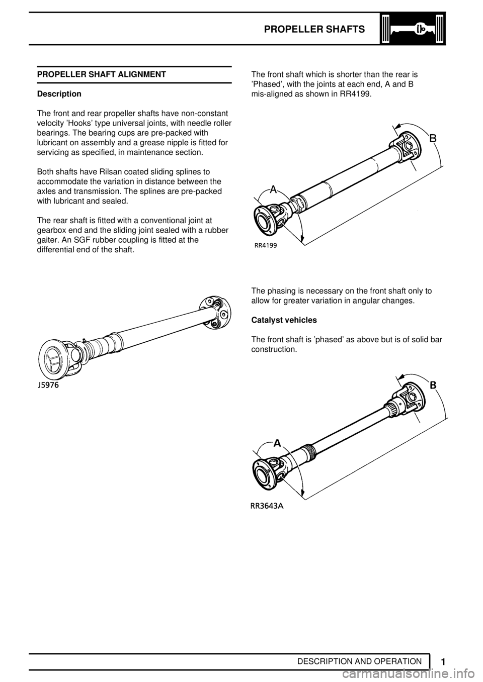
The front shaft which is shorter than the rear is
'Phased', with the joints at each end, A and B
mis-aligned as shown in RR4199.
The phasing is necessary on the front shaft only to
allow for greater variation in angular changes.
Catalyst vehicles
The front shaft is 'phased' as above but is of solid bar
construction.
Page 472 of 976
47PROPELLER SHAFTS
4
REPAIR REAR PROPELLER SHAFT
Service repair no - 47.15.03
NOTE: SGF rubber coupling should be left
attached to propeller shaft. Only remove
coupling from propeller shaft if
replacement is required.
Remove
1.Scribe alignment marks on flanges at both ends
of propeller shaft to ensure correct refitting.
2.Remove three nuts and bolts securing flexible
coupling to axle flange.
3.Remove nuts securing propeller shaft flange to
transfer gearbox.
4.Raise propeller shaft at gearbox end detach
coupling from spigot at differential and withdraw
shaft.
NOTE: For replacement of spigot (pinion
flange centralising peg).
See REAR AXLE
AND FINAL DRIVE, Overhaul, Axle
Differential Assembly
Overhaul
Service repair no - 47.15.12
NOTE: Refer to front propeller shaft
overhaul procedure for gearbox end of
shaft. The SGF rubber coupling is a
non-serviceable item.
Refit
5.Locate flexible coupling over spigot, align
scribed marks and secure at transfer gearbox.
Tighten to
47 Nm.
6.Secure flexible coupling to axle flange with three
nuts and bolts and Tighten to
78 Nm.
FLEXIBLE COUPLING
NOTE: Flexible coupling should only be
removed if a new coupling is to be fitted.
Remove
1.Remove rear propeller shaft.
See Rear
Propeller Shaft.
2.Remove nuts and bolts securing flexible
coupling to propeller shaft.
Refit
3.Reverse removal procedure. Fit nuts and bolts.
Tighten to
78 Nm.
Page 473 of 976
REAR AXLE AND FINAL DRIVE
1
DESCRIPTION AND OPERATION DESCRIPTION
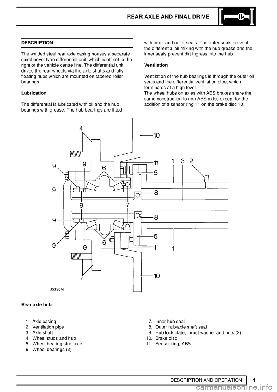
The welded steel rear axle casing houses a separate
spiral bevel type differential unit, which is off set to the
right of the vehicle centre line. The differential unit
drives the rear wheels via the axle shafts and fully
floating hubs which are mounted on tapered roller
bearings.
Lubrication
The differential is lubricated with oil and the hub
bearings with grease. The hub bearings are fittedwith inner and outer seals. The outer seals prevent
the differential oil mixing with the hub grease and the
inner seals prevent dirt ingress into the hub.
Ventilation
Ventilation of the hub bearings is through the outer oil
seals and the differential ventilation pipe, which
terminates at a high level.
The wheel hubs on axles with ABS brakes share the
same construction to non ABS axles except for the
addition of a sensor ring 11 on the brake disc 10.
Rear axle hub
1. Axle casing
2. Ventilation pipe
3. Axle shaft
4. Wheel studs and hub
5. Wheel bearing stub axle
6. Wheel bearings (2)7. Inner hub seal
8. Outer hub/axle shaft seal
9. Hub lock plate, thrust washer and nuts (2)
10. Brake disc
11. Sensor ring, ABS
Page 474 of 976
REAR AXLE AND FINAL DRIVE
1
FAULT DIAGNOSIS FAULT DIAGNOSIS
Complaint - Oil leaks
An external leak of lubrication from the hub seals can
be caused by a faulty internal seal. For example, if the
internal seals which separate the differential from the
hubs are faulty and the vehicle is operating or parked
on an embankment. Oil from the differential may flood
one hub causing a leak and leave the differential
lacking lubrication.
When a seal is found to be leaking check the axle
ventilation system, as a blockage can cause internal
pressure to force oil past the seals.
See 'Description and Operation' for illustrations of oil
seal locations.
When investigating hub seal leaks check the grease
for dilution with oil. Check also the differential level
and oil for metal particles and the condition of internal
seals.
If the vehicle is driven in deep water with defective oil
seals, water may contaminate the lubricants and raise
the differential level giving a false impression that the
housing has been overfilled with oil.
Do not assume that a high oil level in the
differential is due to over filling or, that a low level
is because of an external leak.
Page 475 of 976
REAR AXLE AND FINAL DRIVE
1
REPAIR REAR AXLE
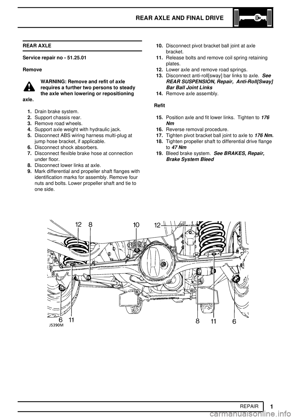
Service repair no - 51.25.01
Remove
WARNING: Remove and refit of axle
requires a further two persons to steady
the axle when lowering or repositioning
axle.
1.Drain brake system.
2.Support chassis rear.
3.Remove road wheels.
4.Support axle weight with hydraulic jack.
5.Disconnect ABS wiring harness multi-plug at
jump hose bracket, if applicable.
6.Disconnect shock absorbers.
7.Disconnect flexible brake hose at connection
under floor.
8.Disconnect lower links at axle.
9.Mark differential and propeller shaft flanges with
identification marks for assembly. Remove four
nuts and bolts. Lower propeller shaft and tie to
one side.10.Disconnect pivot bracket ball joint at axle
bracket.
11.Release bolts and remove coil spring retaining
plates.
12.Lower axle and remove road springs.
13.Disconnect anti-roll[sway] bar links to axle.
See
REAR SUSPENSION, Repair, Anti-Roll[Sway]
Bar Ball Joint Links
14.Remove axle assembly.
Refit
15.Position axle and fit lower links. Tighten to
176
Nm
16.Reverse removal procedure.
17.Tighten pivot bracket ball joint to axle to
176 Nm.
18.Tighten propeller shaft to differential drive flange
to
47 Nm
19.Bleed brake system.See BRAKES, Repair,
Brake System Bleed
Page 479 of 976
REAR AXLE AND FINAL DRIVE
1
OVERHAUL AXLE DIFFERENTIAL ASSEMBLY
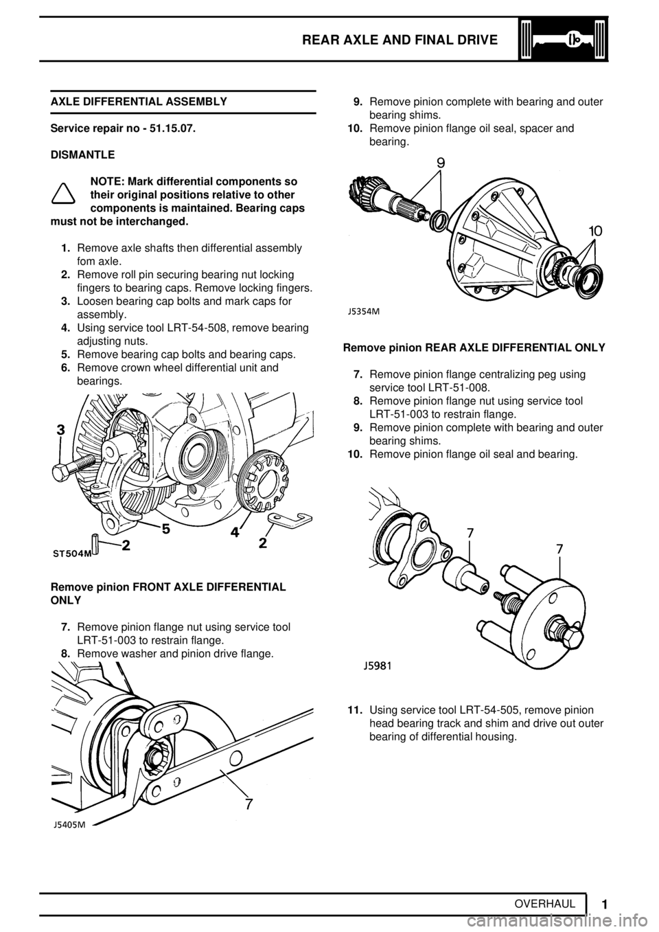
Service repair no - 51.15.07.
DISMANTLE
NOTE: Mark differential components so
their original positions relative to other
components is maintained. Bearing caps
must not be interchanged.
1.Remove axle shafts then differential assembly
fom axle.
2.Remove roll pin securing bearing nut locking
fingers to bearing caps. Remove locking fingers.
3.Loosen bearing cap bolts and mark caps for
assembly.
4.Using service tool LRT-54-508, remove bearing
adjusting nuts.
5.Remove bearing cap bolts and bearing caps.
6.Remove crown wheel differential unit and
bearings.
Remove pinion FRONT AXLE DIFFERENTIAL
ONLY
7.Remove pinion flange nut using service tool
LRT-51-003 to restrain flange.
8.Remove washer and pinion drive flange.
9.Remove pinion complete with bearing and outer
bearing shims.
10.Remove pinion flange oil seal, spacer and
bearing.
Remove pinion REAR AXLE DIFFERENTIAL ONLY
7.Remove pinion flange centralizing peg using
service tool LRT-51-008.
8.Remove pinion flange nut using service tool
LRT-51-003 to restrain flange.
9.Remove pinion complete with bearing and outer
bearing shims.
10.Remove pinion flange oil seal and bearing.
11.Using service tool LRT-54-505, remove pinion
head bearing track and shim and drive out outer
bearing of differential housing.