Page 479 of 976

REAR AXLE AND FINAL DRIVE
1
OVERHAUL AXLE DIFFERENTIAL ASSEMBLY
Service repair no - 51.15.07.
DISMANTLE
NOTE: Mark differential components so
their original positions relative to other
components is maintained. Bearing caps
must not be interchanged.
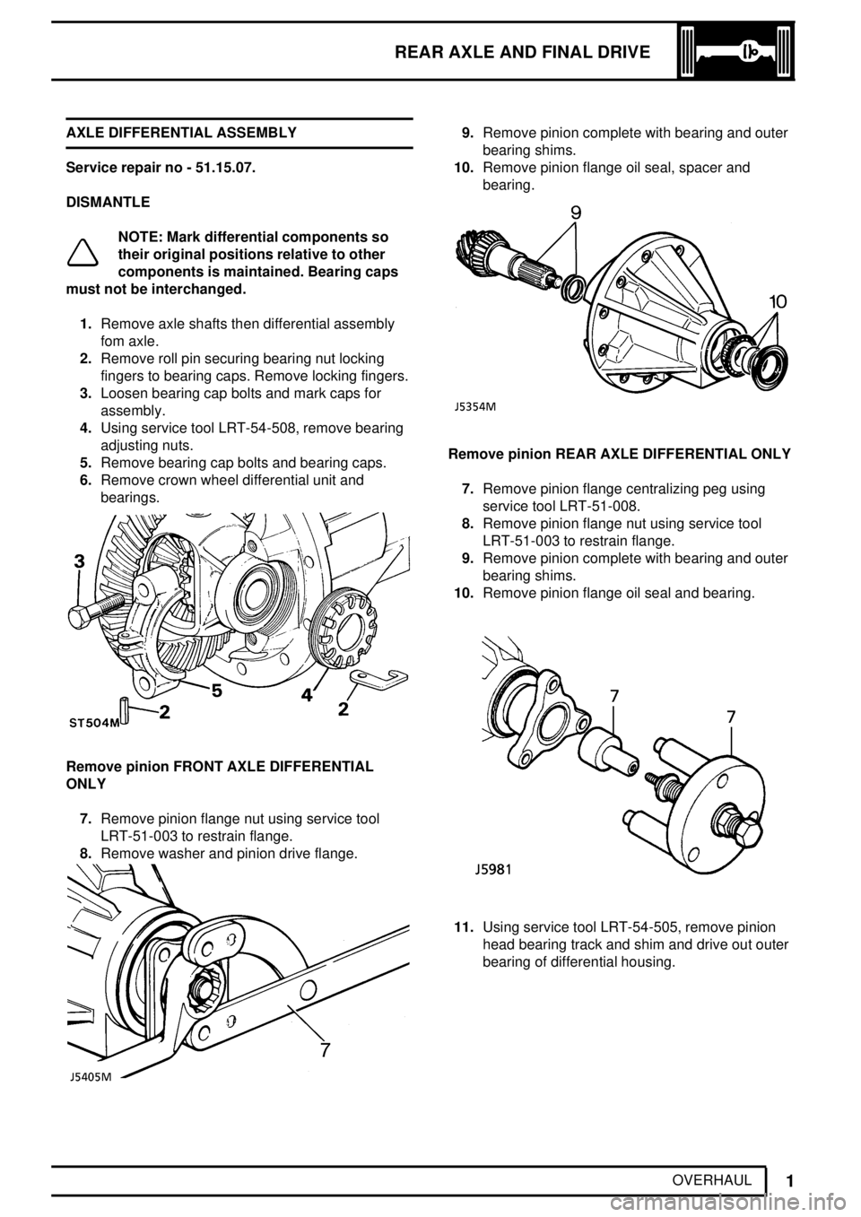
1.Remove axle shafts then differential assembly
fom axle.
2.Remove roll pin securing bearing nut locking
fingers to bearing caps. Remove locking fingers.
3.Loosen bearing cap bolts and mark caps for
assembly.
4.Using service tool LRT-54-508, remove bearing
adjusting nuts.
5.Remove bearing cap bolts and bearing caps.
6.Remove crown wheel differential unit and
bearings.
Remove pinion FRONT AXLE DIFFERENTIAL
ONLY
7.Remove pinion flange nut using service tool
LRT-51-003 to restrain flange.
8.Remove washer and pinion drive flange.
9.Remove pinion complete with bearing and outer
bearing shims.
10.Remove pinion flange oil seal, spacer and
bearing.
Remove pinion REAR AXLE DIFFERENTIAL ONLY
7.Remove pinion flange centralizing peg using
service tool LRT-51-008.
8.Remove pinion flange nut using service tool
LRT-51-003 to restrain flange.
9.Remove pinion complete with bearing and outer
bearing shims.
10.Remove pinion flange oil seal and bearing.
11.Using service tool LRT-54-505, remove pinion
head bearing track and shim and drive out outer
bearing of differential housing.
Page 481 of 976

REAR AXLE AND FINAL DRIVE
3
OVERHAUL 23.Check gear for freedom of rotation and backlash.
Nominal backlash should be present. Excess
backlash necessitates replacement of gears or
differential housing.
24.Check serial number marked on pinion end face
matches that on crown wheel.
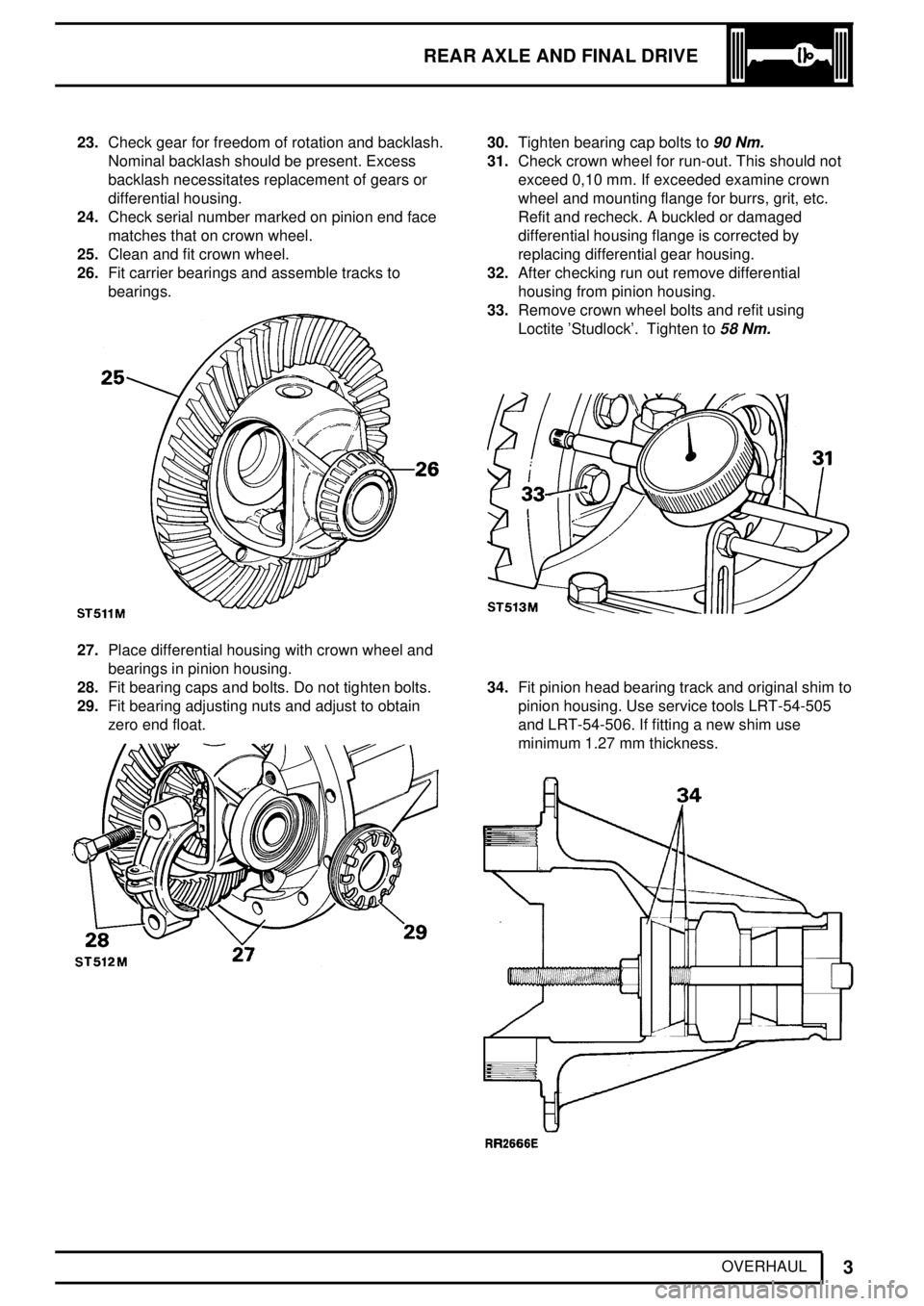
25.Clean and fit crown wheel.
26.Fit carrier bearings and assemble tracks to
bearings.
27.Place differential housing with crown wheel and
bearings in pinion housing.
28.Fit bearing caps and bolts. Do not tighten bolts.
29.Fit bearing adjusting nuts and adjust to obtain
zero end float.
30.Tighten bearing cap bolts to90 Nm.
31.Check crown wheel for run-out. This should not
exceed 0,10 mm. If exceeded examine crown
wheel and mounting flange for burrs, grit, etc.
Refit and recheck. A buckled or damaged
differential housing flange is corrected by
replacing differential gear housing.
32.After checking run out remove differential
housing from pinion housing.
33.Remove crown wheel bolts and refit using
Loctite 'Studlock'. Tighten to
58 Nm.
34.Fit pinion head bearing track and original shim to
pinion housing. Use service tools LRT-54-505
and LRT-54-506. If fitting a new shim use
minimum 1.27 mm thickness.
Page 483 of 976

REAR AXLE AND FINAL DRIVE
5
OVERHAUL
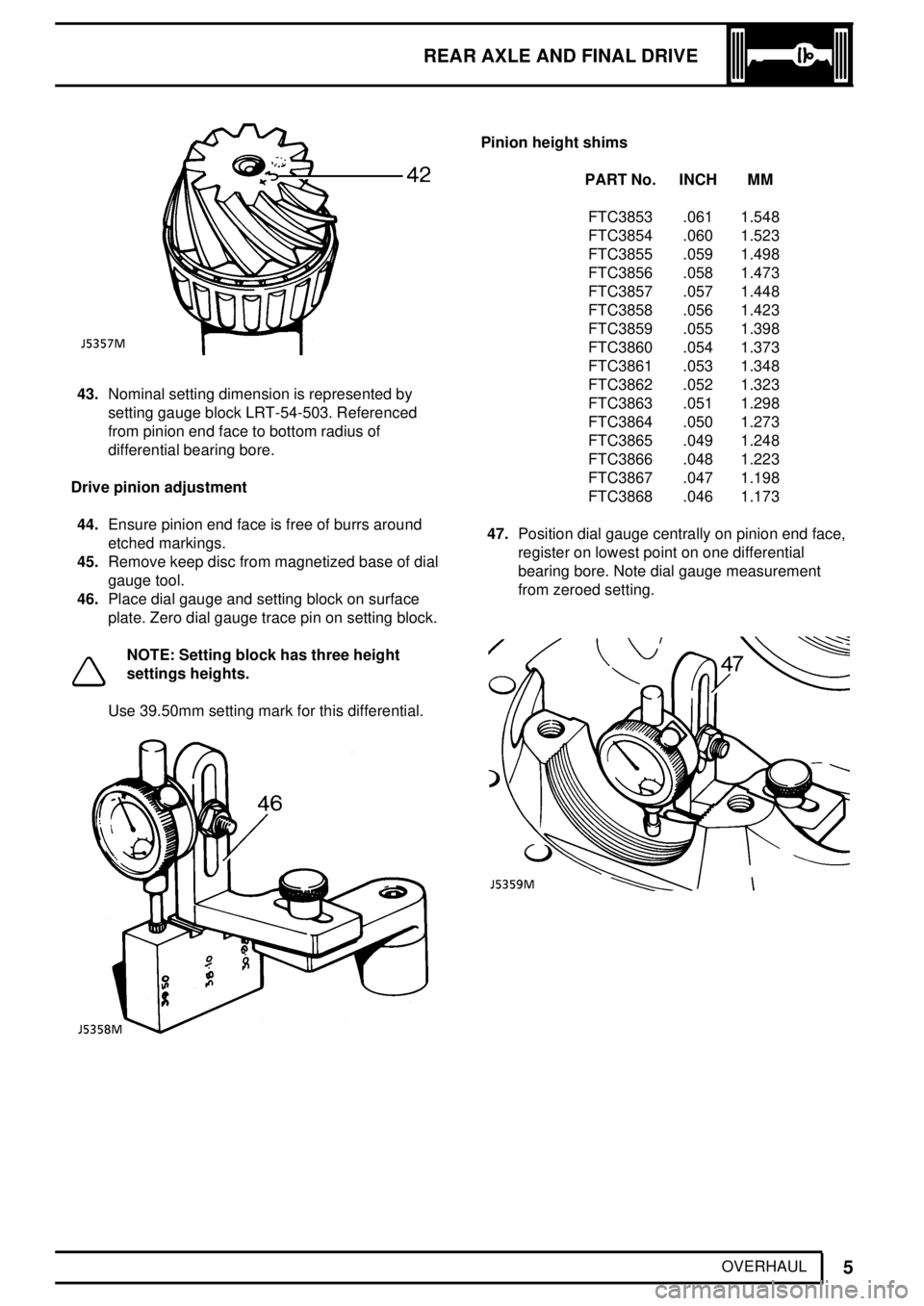
43.Nominal setting dimension is represented by
setting gauge block LRT-54-503. Referenced
from pinion end face to bottom radius of
differential bearing bore.
Drive pinion adjustment
44.Ensure pinion end face is free of burrs around
etched markings.
45.Remove keep disc from magnetized base of dial
gauge tool.
46.Place dial gauge and setting block on surface
plate. Zero dial gauge trace pin on setting block.
NOTE: Setting block has three height
settings heights.
Use 39.50mm setting mark for this differential.
Pinion height shims
PART No. INCH MM
FTC3853 .061 1.548
FTC3854 .060 1.523
FTC3855 .059 1.498
FTC3856 .058 1.473
FTC3857 .057 1.448
FTC3858 .056 1.423
FTC3859 .055 1.398
FTC3860 .054 1.373
FTC3861 .053 1.348
FTC3862 .052 1.323
FTC3863 .051 1.298
FTC3864 .050 1.273
FTC3865 .049 1.248
FTC3866 .048 1.223
FTC3867 .047 1.198
FTC3868 .046 1.173
47.Position dial gauge centrally on pinion end face,
register on lowest point on one differential
bearing bore. Note dial gauge measurement
from zeroed setting.
Page 486 of 976
51REAR AXLE AND FINAL DRIVE
8
OVERHAUL CROWN WHEEL/PINION BACKLASH
ADJUSTMENT
63.Place differential housing in pinion housing.
64.Fit bearing caps and partly tighten bolts.
65.Fit bearing adjusting nuts.
66.Mesh crown wheel to pinion. Using service tool
LRT-54-508 loosen left bearing adjuster nut.
67.Tighten right nut until crown wheel/pinion
backlash is just removed.68.Tighten left nut until it contacts bearing. Continue
turning until a backlash of 0,10 to 0,17 mm is
met.DO NOTloosen right nut otherwise bearing
preload will be affected.
69.Fit locking fingers and roll pins. Align locking
finger with a slot.
70.Evenly tighten bearing cap bolts to
90 Nm.
71.Recheck crown wheel/pinion backlash.
72.Lubricate bearings and gears.
Page 487 of 976
REAR AXLE AND FINAL DRIVE
9
OVERHAUL REAR HUB ASSEMBLY
Service repair no - 61.15.13.
Overhaul
1.Remove rear hub assembly.
See Repair, Rear
Hub Assembly
2.Remove outer bearing.
3.Remove five nyloc nuts and withdraw ABS
sensor ring, if applicable.
4.Mark, for reassembly, position of hub to brake
disc.5.Remove five bolts and separate hub from brake
disc.
WARNING: A maximum of two road wheel
retaining studs can be renewed. Should
more studs be unserviceable fit new hub
with studs.
6.Remove grease seal and inner bearing from
hub.
7.Remove inner and outer bearing tracks.
REAR HUB COMPONENTS
1. Sensor ring retaining nut ABS.
2. Axle shaft.
3. Axle shaft joint washer.
4. Axle shaft retaining bolt (five off).
5. Lock nut.
6. Lock washer.
7. Hub adjusting nut.
8. Spacing washer.9. Outer bearing.
10. Hub.
11. Inner bearing.
12. Grease seal.
13. Brake disc.
14. Disc retaining bolt (five off).
15. Sensor ring ABS.
Page 492 of 976
REAR AXLE AND FINAL DRIVE
1
SERVICE TOOLS AXLE DIFFERENTIAL
LRT-51-003 Flange holder tool
18G1205
LRT-54-504 Universal setting block
18G1914
LRT-54-502 Pinion head bearing remover/replacer
18G476
LRT-99-002 Press
MS47
Page 497 of 976
54FRONT AXLE AND FINAL DRIVE
2
DESCRIPTION AND OPERATION
Front axle
1. Axle casing
2. Ventilation pipe
3. Axle shaft
4. Wheel studs and hub
5. Stub axle
6. Wheel bearings (2)
7. Inner and outer hub seals
8. Axle shaft seal
9. Hub lock plate, thrust washer and nuts (2)
10. Brake disc
11. Drive flange
12. Shim washer and circlip
13. Dust cap14. Constant velocity joint/shaft
15. Thrust collar for CV joint
16. Roller bearing
17. Spacer
18. Circlip
19. Bottom swivel taper bearing
20. Top and bottom swivel pins
21. Spherical housing, seal and retainer
22. Swivel housing
23. Constant velocity shaft seal
24. ABS pickup (electrical connection)
25. 'Rialco' bush ABS
Page 498 of 976

FRONT AXLE AND FINAL DRIVE
1
FAULT DIAGNOSIS FAULT DIAGNOSIS
Complaint - Oil leaks
An external leak of lubrication can be caused by a
faulty internal seal. For example, if the seals which
separate the differential from the swivel housings are
faulty and the vehicle is operating or parked on an
embankment, oil may leak across the axle leaving one
swivel with a high level and the other swivel and
differential lacking lubrication.
See 'Description and Operation' for illustrations of oil
seal locations.
When investigating leaks or checking oil levels, it is
essential that all the lubrication is drained from any
housing with a high level and that the other levels are
checked.
Swivel oil should be checked for signs of grease
leaking from the hub bearings and the hub grease
should not contain oil.
Check that the axle ventilation system is clear, as a
blockage can cause internal pressure to force oil past
the seals.
If the vehicle is driven in deep water with defective oil
seals, water may contaminate the lubricants and when
checked, give a false impression that the housing has
been overfilled with oil.
Do not assume that a high oil level is due to over
filling or, that a low level is because of an external
leak.