Page 49 of 976
05ENGINE TUNING DATA
6
INFORMATION ENGINE - Mpi - 2.0 LITRE
Type/Capacity 20 T4/1994 cm
3..................................................................
Firing order 1-3-4-2.......................................................................
Compression ration 10 : 1..........................................................
Idle speed:
Controlled by ECM 875±50 rev/min ...........................................................
Exhaust gas Co content:
- Catalyst 0.5% Max. Not adjustable..................................................................
- Non Catalyst 1,0±25% adjustable using Testbook .........................................................
Ignition
Knock sensor ADU 8229...................................................................
Crankshaft sensor ADU 7340............................................................
Ignition Coils
Type NEC 10049.................................................................................
Primary resistance at 20°C 0.4 to 0.61 ohm..............................................
Consumption - engine idling 0.25 to 0.75 amp.............................................
Spark Plugs
Type/Gap GSP 6662 -0,85 mm.........................................................................
Multipoint Fuel Injection
Type Indirect multipoint injection with engine control module.................................................................................
using speed/density method of air flow measurement.
Fuel pressure regulator MKW 10011....................................................
Fuel pump delivery pressure 2.3 - 2.5 bar............................................
Throttle potentiometer voltage
- Throttle closed 0 - 1 Volt......................................................
- Throttle open 4 - 5 Volts.........................................................
MEMS engine control module MKC 10121..........................................
95 RON minimum -UNLEADEDfuel
CAUTION: Do not use LEADED fuel as it will
damage the catalyst. Serious damage to the
engine may occur if a lower octane number fuel
than that recommended is used.
Page 61 of 976
LUBRICANTS, FLUIDS AND CAPACITIES
5
INFORMATION ANTI-FREEZE
ENGINE TYPE MIXTURE STRENGTH PERCENTAGE PROTECTION
CONCENTRATION LOWER
TEMPERATURE
LIMIT
V8i Engine One part anti-freeze
Diesel Engine One part water 50%
Complete protection-33°F
Vehicle may be driven away immediately from cold - 36°C
Safe limit protection-41°C
Coolant in mushy state. Engine may be started and driven away after warm-up
period-42°F
Lower protection-47°C
Prevents frost damage to cylinder head, block and radiator. Thaw out before
starting engine-53°F
CAUTION: Anti-freeze content must never be allowed to fall below 25% otherwise damage to the
engine is liable to occur. Also, anti-freeze content should not exceed 60% as this will greatly
reduce the cooling effect of the coolant.
FUEL REQUIREMENTS
Catalyst vehicles
Vehicles equipped with catalytic converter are designed to use ONLY unleaded fuel. Unleaded fuel must be used
for the emission control system to operate properly. Its use will also reduce spark plug fouling, exhaust system
corrosion and engine oil deterioration.
Using fuel that contains lead will result in damage to the emission control system and could result in loss of
warranty coverage. The effectiveness of the catalysts in the catalytic converters will be seriously impaired if leaded
fuel is used. The vehicle is equipped with an electronic fuel injection system, which includes two oxygen sensors.
Leaded fuel will damage the sensors, and will deteriorate the emission control system.
Regulations require that pumps delivering unleaded fuel be labelledUNLEADED.Only these pumps have nozzles
which fit the filler neck of the vehicle fuel tank.
Page 69 of 976
MAINTENANCE
7
MAINTENANCE
CHECK/ADJUST VALVE CLEARANCES. - Tdi
Valve adjustment.See GENERAL SPECIFICATION
DATA, Information, 300 Tdi Engine
RENEW FUEL FILTER ELEMENT - Tdi
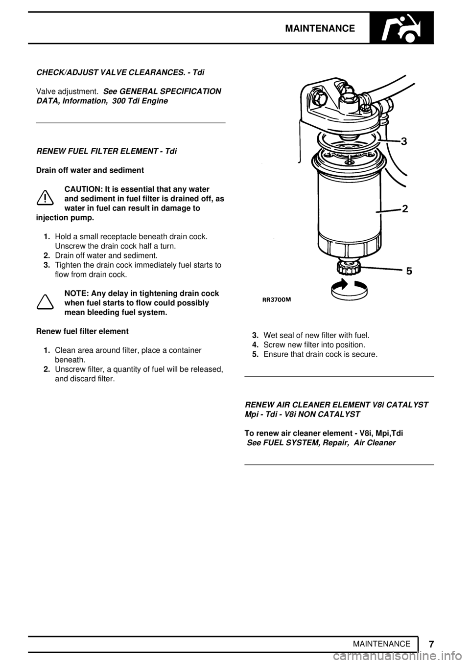
Drain off water and sediment
CAUTION: It is essential that any water
and sediment in fuel filter is drained off, as
water in fuel can result in damage to
injection pump.
1.Hold a small receptacle beneath drain cock.
Unscrew the drain cock half a turn.
2.Drain off water and sediment.
3.Tighten the drain cock immediately fuel starts to
flow from drain cock.
NOTE: Any delay in tightening drain cock
when fuel starts to flow could possibly
mean bleeding fuel system.
Renew fuel filter element
1.Clean area around filter, place a container
beneath.
2.Unscrew filter, a quantity of fuel will be released,
and discard filter.
3.Wet seal of new filter with fuel.
4.Screw new filter into position.
5.Ensure that drain cock is secure.
RENEW AIR CLEANER ELEMENT V8i CATALYST
Mpi - Tdi - V8i NON CATALYST
To renew air cleaner element - V8i, Mpi,Tdi
See FUEL SYSTEM, Repair, Air Cleaner
Page 79 of 976
MAINTENANCE
17
MAINTENANCE
CHECK/TIGHTEN FRONT AND REAR AXLE
SUSPENSION LINK FIXINGS, CHECK CONDITION
OF MOUNTING RUBBERS
DRAIN FUEL SEDIMENTER - Tdi
Fuel sedimenter
The sedimenter is attached to left-hand side of
chassis frame near fuel tank. It increases the working
life of the fuel filter by removing larger droplets of
water and larger particles of foreign matter from fuel.
Drain off water
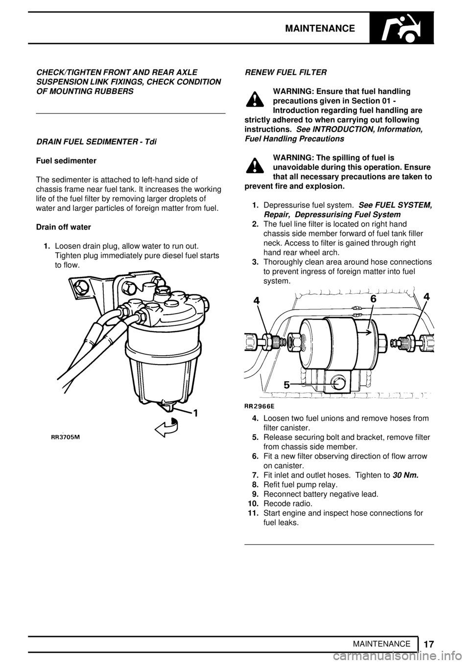
1.Loosen drain plug, allow water to run out.
Tighten plug immediately pure diesel fuel starts
to flow.
RENEW FUEL FILTER
WARNING: Ensure that fuel handling
precautions given in Section 01 -
Introduction regarding fuel handling are
strictly adhered to when carrying out following
instructions.
See INTRODUCTION, Information,
Fuel Handling Precautions
WARNING: The spilling of fuel is
unavoidable during this operation. Ensure
that all necessary precautions are taken to
prevent fire and explosion.
1.Depressurise fuel system.
See FUEL SYSTEM,
Repair, Depressurising Fuel System
2.The fuel line filter is located on right hand
chassis side member forward of fuel tank filler
neck. Access to filter is gained through right
hand rear wheel arch.
3.Thoroughly clean area around hose connections
to prevent ingress of foreign matter into fuel
system.
4.Loosen two fuel unions and remove hoses from
filter canister.
5.Release securing bolt and bracket, remove filter
from chassis side member.
6.Fit a new filter observing direction of flow arrow
on canister.
7.Fit inlet and outlet hoses. Tighten to
30 Nm.
8.Refit fuel pump relay.
9.Reconnect battery negative lead.
10.Recode radio.
11.Start engine and inspect hose connections for
fuel leaks.
Page 85 of 976
12ENGINE
4
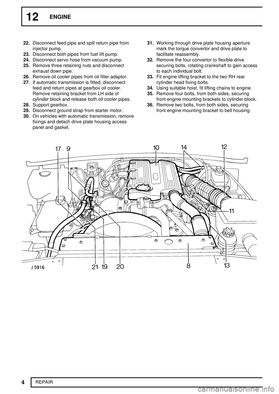
REPAIR 22.Disconnect feed pipe and spill return pipe from
injector pump.
23.Disconnect both pipes from fuel lift pump.
24.Disconnect servo hose from vacuum pump.
25.Remove three retaining nuts and disconnect
exhaust down pipe.
26.Remove oil cooler pipes from oil filter adaptor.
27.If automatic transmission is fitted, disconnect
feed and return pipes at gearbox oil cooler.
Remove retaining bracket from LH side of
cylinder block and release both oil cooler pipes.
28.Support gearbox.
29.Disconnect ground strap from starter motor.
30.On vehicles with automatic transmission, remove
fixings and detach drive plate housing access
panel and gasket.31.Working through drive plate housing aperture
mark the torque convertor and drive plate to
facilitate reassembly.
32.Remove the four convertor to flexible drive
securing bolts, rotating crankshaft to gain access
to each individual bolt.
33.Fit engine lifting bracket to the two RH rear
cylinder head fixing bolts.
34.Using suitable hoist, fit lifting chains to engine.
35.Remove four bolts, from both sides, securing
front engine mounting brackets to cylinder block.
36.Remove two bolts, from both sides, securing
front engine mounting bracket to bell housing.
Page 91 of 976
12ENGINE
10
REPAIR
21.With lip side leading, drive-in seal squarely using
special tool LRT-12-082.
22.Refit gear.
FUEL INJECTION PUMP GEAR
Service repair no - 19.30.06
Remove
23.Slacken the three bolts on front of gear.
CAUTION: It is important to ensure that
when the injection pump is locked no
attempt must be made to rotate it. Take
care not to allow the crankshaft to be turned.24.Remove special tool pin from gear.
25.Remove three bolts and withdraw plate and
gear.
Refit
26.Fit gear and plate and secure with three bolts.
27.Insert pin from special tool LRT-12-045 in
injection pump gear and through into pump
flange.
Page 93 of 976
12ENGINE
12
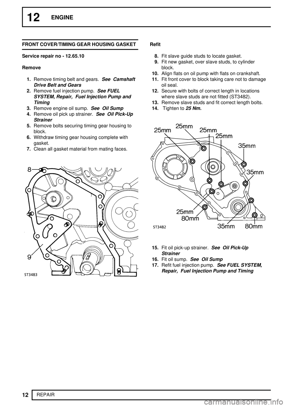
REPAIR FRONT COVER/TIMING GEAR HOUSING GASKET
Service repair no - 12.65.10
Remove
1.Remove timing belt and gears.
See Camshaft
Drive Belt and Gears
2.Remove fuel injection pump.See FUEL
SYSTEM, Repair, Fuel Injection Pump and
Timing
3.Remove engine oil sump.See Oil Sump
4.Remove oil pick up strainer.See Oil Pick-Up
Strainer
5.Remove bolts securing timing gear housing to
block.
6.Withdraw timing gear housing complete with
gasket.
7.Clean all gasket material from mating faces.
Refit
8.Fit slave guide studs to locate gasket.
9.Fit new gasket, over slave studs, to cylinder
block.
10.Align flats on oil pump with flats on crankshaft.
11.Fit front cover to block taking care not to damage
oil seal.
12.Secure with bolts of correct length in locations
where slave studs are not fitted (ST3482).
13.Remove slave studs and fit correct length bolts.
14.Tighten to
25 Nm.
15.Fit oil pick-up strainer.See Oil Pick-Up
Strainer
16.Fit oil sump.See Oil Sump
17.Refit fuel injection pump.See FUEL SYSTEM,
Repair, Fuel Injection Pump and Timing
Page 101 of 976
![LAND ROVER DISCOVERY 1995 Service Repair Manual 12ENGINE
20
REPAIR CYLINDER HEAD GASKET
Service repair no - 12.29.02
Remove
1.Disconnect battery negative lead.
2.Remove bonnet [Hood].
See CHASSIS AND
BODY, Repair, Bonnet [Hood]
3.Drain coolant.
4.R LAND ROVER DISCOVERY 1995 Service Repair Manual 12ENGINE
20
REPAIR CYLINDER HEAD GASKET
Service repair no - 12.29.02
Remove
1.Disconnect battery negative lead.
2.Remove bonnet [Hood].
See CHASSIS AND
BODY, Repair, Bonnet [Hood]
3.Drain coolant.
4.R](/manual-img/64/57245/w960_57245-100.png)
12ENGINE
20
REPAIR CYLINDER HEAD GASKET
Service repair no - 12.29.02
Remove
1.Disconnect battery negative lead.
2.Remove bonnet [Hood].
See CHASSIS AND
BODY, Repair, Bonnet [Hood]
3.Drain coolant.
4.Remove air cleaner assembly.
See FUEL
SYSTEM, Repair, Air Cleaner
5.Detach crankcase ventilation valve and side
breather hose from rocker cover and move to
one side.
6.Remove injection pipes.
7.Disconnect spill rail from fuel injectors.
8.Remove fuel injectors and sealing washers.
Identify each injector to the location from which it
is removed.
See FUEL SYSTEM, Repair,
Injectors
9.Remove inter-connecting harness from glow
plugs.
10.Remove glow plugs.
See FUEL SYSTEM,
Repair, Glow Plugs
11.Remove top hose, radiator to thermostat.
12.Disconnect by-pass hose from thermostat.
13.Disconnect hose, thermostat to water pump.
14.Disconnect water temperature sensor lead.
15.Remove hose inter-cooler to induction manifold.
16.Remove induction manifold.
See MANIFOLD
AND EXHAUST SYSTEM, Repair, Exhaust
Manifold - Tdi
17.Remove exhaust manifold and turbocharger
assembly.
See MANIFOLD AND EXHAUST
SYSTEM, Repair, Exhaust Manifold - Tdi
18.Disconnect heater hose from water pump and
move heater rail aside.
19.Disconnect heater hose from rear of cylinder
head.
20.Remove bolt securing air cleaner mounting
bracket to support strut.
21.Remove bolt securing harness bracket to
cylinder head.
22.Remove rear lifting bracket, this will also release
clips securing transmission and engine breather
pipes and multiplug. Note loose spacer under
clip securing engine breather pipe and multiplug.