Page 956 of 976
ENGINE
OVERHAUL61
Crankshaft end-float - checking
1.Lubricate upper main bearing shells and
crankshaft main bearing journals with engine
oil.
2.Lubricate new standard size thrust washers
with engine oil and position washers in recess
in centre main bearing saddle.
NOTE: Grooved side of washers must face
outwards.
3.Using assistance, fit crankshaft.
4.Attach a DTI to rear face of cylinder block with
stylus contacting end of crankshaft; push
crankshaft fully rearwards and zero gauge.
5.Push crankshaft fully forwards and measure
end-float.
6.If end-float exceeds 0.05 to 0.15 mm, remove
crankshaft, fit combinations of standard and
oversize thrust washers to achieve correct
end-float.
CAUTION: Variations of thrust washer
thicknesses on each side of crankshaft
must not exceed 0.08 mm.
7.When end-float is correct, remove DTI.
8.Using assistance, remove crankshaft and
thrust washers. Ensure that thrust washers are
identified to their location.
Page 957 of 976

ENGINE
62
OVERHAUL Big-end bearing clearance - checking
1.Fit pistons and connecting rods.
2.Degrease new big-end bearing shells.
3.Fit big-end bearing shells to connecting rods
ensuring that tag is located in recess in
connecting rod.
4.Fit big-end bearing shells to bearing caps
ensuring that tag is located in recess in cap.
5.Temporarily fit crankshaft pulley bolt and rotate
crankshaft to bring numbers 1 and 4 journals to
BDC.
6.Remove all traces of oil from crankshaft
journals.
7.Pull numbers 1 and 4 connecting rods on to
crankshaft journals, remove plastic tubing from
connecting rod bolts.
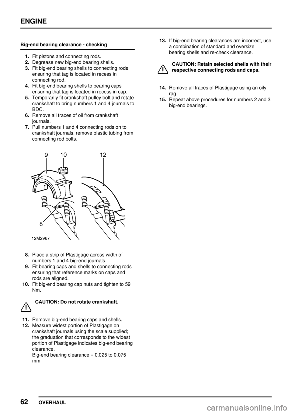
8.Place a strip of Plastigage across width of
numbers 1 and 4 big-end journals.
9.Fit bearing caps and shells to connecting rods
ensuring that reference marks on caps and
rods are aligned.
10.Fit big-end bearing cap nuts and tighten to 59
Nm.
CAUTION: Do not rotate crankshaft.
11.Remove big-end bearing caps and shells.
12.Measure widest portion of Plastigage on
crankshaft journals using the scale supplied;
the graduation that corresponds to the widest
portion of Plastigage indicates big-end bearing
clearance.
Big-end bearing clearance = 0.025 to 0.075
mm13.If big-end bearing clearances are incorrect, use
a combination of standard and oversize
bearing shells and re-check clearance.
CAUTION: Retain selected shells with their
respective connecting rods and caps.
14.Remove all traces of Plastigage using an oily
rag.
15.Repeat above procedures for numbers 2 and 3
big-end bearings.
Page 959 of 976

ENGINE
64
OVERHAUL 8.Tighten centre main bearing cap bolts to 133
Nm.
9.Temporarily fit crankshaft pulley bolt and check
that crankshaft rotates freely and smoothly.
10.Tighten each pair of main bearing cap bolts to
133 Nm in the order No. 2, No. 4, No. 1 and
No. 5. Check that crankshaft rotates freely and
smoothly after tightening each pair of bolts.
11.Remove seal guidesLRT-12-035and select
feeler gauges to a thickness of 0.80 mm,
position gauges on number 5 main bearing cap
adjacent to oil seals.
12.Position a sharp blade on feeler gauges and
keeping blade parallel to bearing cap, slice
excess material off oil seal
13.Repeat above procedures for remaining seal.
CAUTION: Seals should be left to settle for
as long as possible before they are
trimmed.Big-end bearings
1.Lubricate big-end bearing shells and
crankshaft journals with engine oil.
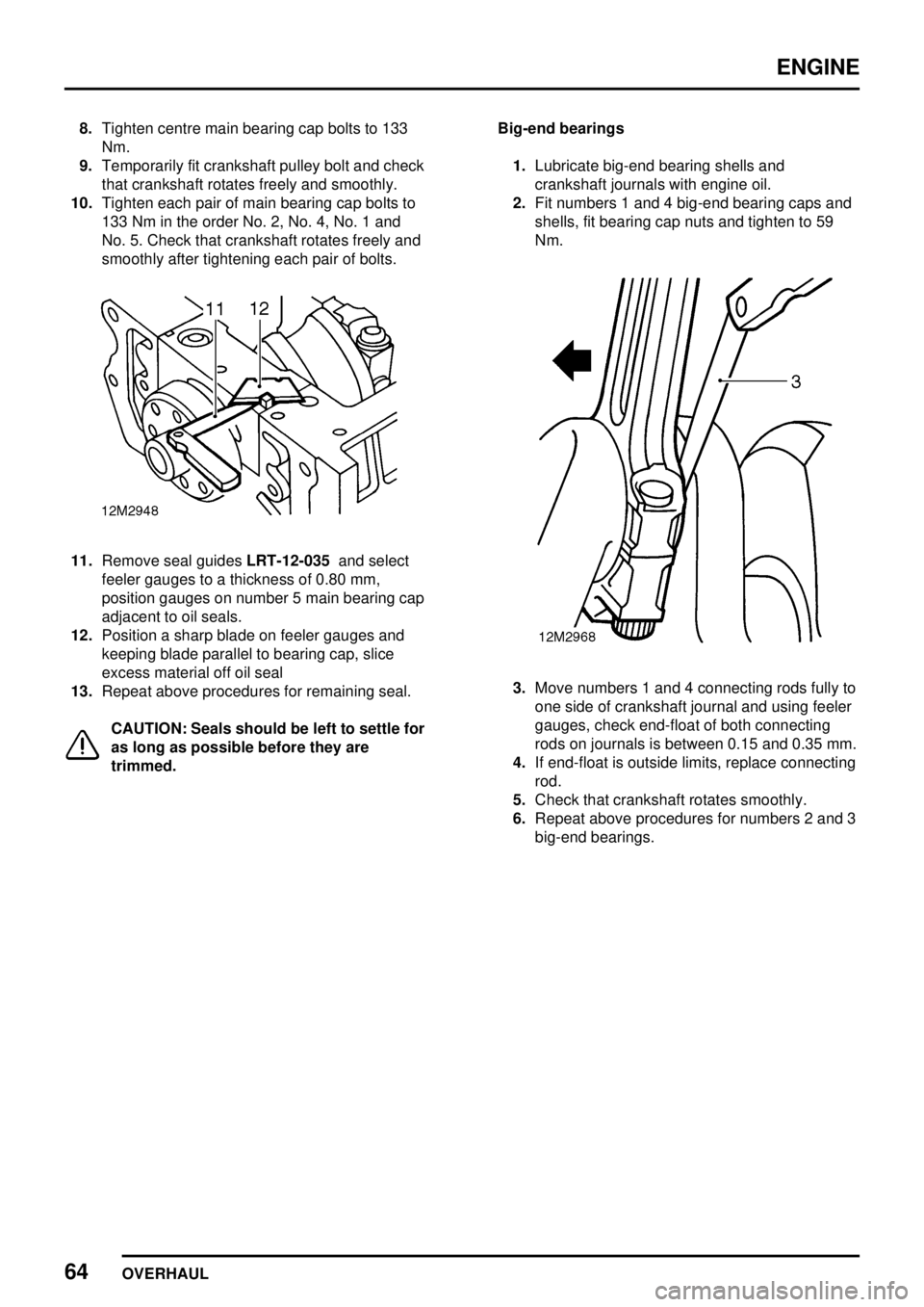
2.Fit numbers 1 and 4 big-end bearing caps and
shells, fit bearing cap nuts and tighten to 59
Nm.
3.Move numbers 1 and 4 connecting rods fully to
one side of crankshaft journal and using feeler
gauges, check end-float of both connecting
rods on journals is between 0.15 and 0.35 mm.
4.If end-float is outside limits, replace connecting
rod.
5.Check that crankshaft rotates smoothly.
6.Repeat above procedures for numbers 2 and 3
big-end bearings.
Page 964 of 976
ENGINE
OVERHAUL69
11.Assemble each big-end bearing cap less
bearing shells to its respective connecting rod.
12.Fit and tighten big-end bearing cap nuts to 59
Nm.
13.Slacken the nut on one side of connecting rod.
14.Using feeler gauges, check that there is no gap
between bearing cap and connecting rod on
the side of the cap with the slackened nut.
CAUTION: If clearance exists, connecting
rod must be replaced.
15.Remove nuts and big-end bearing caps.
CAUTION: Retain nuts and bearing caps
with their respective connecting rod
16.Repeat above procedures for remaining
connecting rods.17.Lubricate gudgeon pins and small end bushes
with engine oil.
18.Assemble each connecting rod and gudgeon
pin to its respective piston ensuring that
bearing tag recess on connecting rod is on
correct side of piston.
19.Fit new circlips to retain gudgeon pins ensuring
they are correctly seated in their grooves.
Page 965 of 976
ENGINE
70
OVERHAUL Piston rings - checking
CAUTION: Prior to checking piston ring
gaps in cylinder bores, bores must be
inspected, measured and if reboring has
been carried out, the appropriate oversize
pistons and rings used.
1.Check fitted gap of each new piston ring in turn
with ring positioned half-way down cylinder
bore.
Fitted gap of rings in bores:
Top compression = 0.40 to 0.65 mm
2nd compression = 0.30 to 0.50 mm
Oil control rails = 0.30 to 0.60 mm
CAUTION: Ensure that piston rings are
suitably identified with the cylinder bore in
which they were checked and that they are
fitted to the piston for that cylinder bore.
2.Fit oil control rails and spring to piston.
3.Fit 2nd, narrow compression ring with 'TOP'
marking uppermost.
4.Fit top compression ring with 'TOP' marking
uppermost.
5.Check that rings are free to rotate in their
grooves.
Page 966 of 976
ENGINE
OVERHAUL71
6.Check ring to groove clearances:
Top compression = 0.167 to 0.232 mm
2nd compression = 0.05 to 0.08 mm
Oil control rails = 0.05 to 0.08 mm
7.If new ring to groove clearances are excessive,
new pistons must be fitted.Oil jet tubes - inspection
1.Check that oil passage in each oil jet tube is
clear.
2.Thoroughly clean banjo bolts.
3.Insert a piece of stiff wire in end of banjo bolt
and check that non-return valve can be
depressed to open position and returns to
closed position under spring pressure.
CAUTION: If non-return valve is not
working correctly, replace banjo bolt.
4.Check sealing washers for damage, replace as
necessary.
Page 969 of 976

ENGINE
74
OVERHAUL
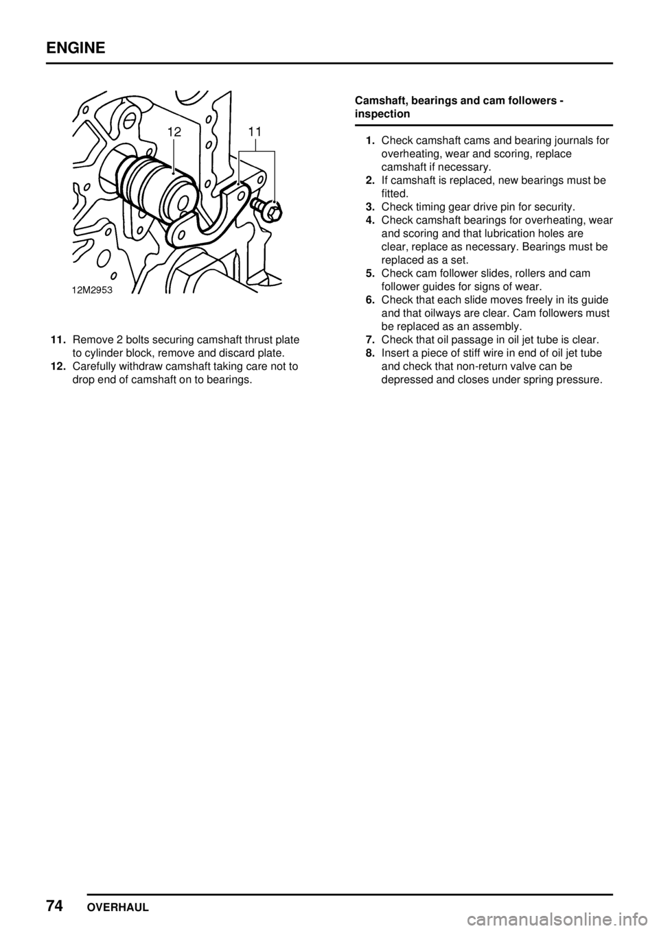
11.Remove 2 bolts securing camshaft thrust plate
to cylinder block, remove and discard plate.
12.Carefully withdraw camshaft taking care not to
drop end of camshaft on to bearings.Camshaft, bearings and cam followers -
inspection
1.Check camshaft cams and bearing journals for
overheating, wear and scoring, replace
camshaft if necessary.
2.If camshaft is replaced, new bearings must be
fitted.
3.Check timing gear drive pin for security.
4.Check camshaft bearings for overheating, wear
and scoring and that lubrication holes are
clear, replace as necessary. Bearings must be
replaced as a set.
5.Check cam follower slides, rollers and cam
follower guides for signs of wear.
6.Check that each slide moves freely in its guide
and that oilways are clear. Cam followers must
be replaced as an assembly.
7.Check that oil passage in oil jet tube is clear.
8.Insert a piece of stiff wire in end of oil jet tube
and check that non-return valve can be
depressed and closes under spring pressure.
Page 970 of 976

ENGINE
OVERHAUL75
Camshaft - refit and check end-float
1.Remove all traces of gasket from baffle plate
and cylinder block using suitable gasket
removal spray and a plastic scraper.
2.Lubricate cams, journals and bearings with
engine oil.
3.Ensure thrust plate bolt holes in cylinder block
are clean and dry.
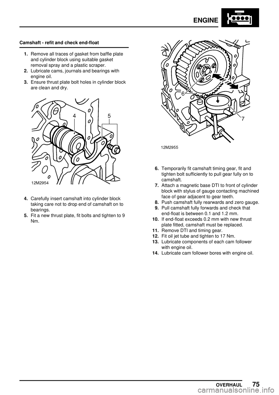
4.Carefully insert camshaft into cylinder block
taking care not to drop end of camshaft on to
bearings.
5.Fit a new thrust plate, fit bolts and tighten to 9
Nm.
6.Temporarily fit camshaft timing gear, fit and
tighten bolt sufficiently to pull gear fully on to
camshaft.
7.Attach a magnetic base DTI to front of cylinder
block with stylus of gauge contacting machined
face of gear adjacent to gear teeth.
8.Push camshaft fully rearwards and zero gauge.
9.Pull camshaft fully forwards and check that
end-float is between 0.1 and 1.2 mm.
10.If end-float exceeds 0.2 mm with new thrust
plate fitted, camshaft must be replaced.
11.Remove DTI and timing gear.
12.Fit oil jet tube and tighten to 17 Nm.
13.Lubricate components of each cam follower
with engine oil.
14.Lubricate cam follower bores with engine oil.