1995 JEEP YJ ground system
[x] Cancel search: ground systemPage 28 of 2158

JUMP STARTING, TOWING AND HOISTING
INDEX
page page
Four-Wheel-Drive Vehicle Towing............. 12
Ground Clearance and Ramp Angle............ 11
Hoisting Recommendations.................. 10
Jump Starting Procedure..................... 9Towing Recommendations................... 10
Towing When Keys Are Not Available.......... 13
Two-Wheel-Drive Vehicle TowingÐXJ.......... 11
JUMP STARTING PROCEDURE
WARNING: DO NOT ATTEMPT TO PUSH OR TOW A
VEHICLE TO START THE ENGINE. UNBURNED
FUEL COULD ENTER THE EXHAUST CATALYTIC
CONVERTER AND IGNITE AFTER THE ENGINE IS
STARTED. THIS COULD CAUSE THE CONVERTER
TO OVERHEAT AND RUPTURE.
WARNING: REVIEW ALL SAFETY PRECAUTIONS
AND WARNINGS IN GROUP 8A, BATTERY/START-
ING/CHARGING SYSTEMS DIAGNOSTICS.
DO NOT JUMP START A FROZEN BATTERY, PER-
SONAL INJURY CAN RESULT.
DO NOT JUMP START WHEN MAINTENANCE
FREE BATTERY INDICATOR DOT IS YELLOW OR
BRIGHT COLOR.
DO NOT JUMP START A VEHICLE WHEN THE
BATTERY FLUID IS BELOW THE TOP OF LEAD
PLATES.
DO NOT ALLOW JUMPER CABLE CLAMPS TO
TOUCH EACH OTHER WHEN CONNECTED TO A
BOOSTER SOURCE.
DO NOT USE OPEN FLAME NEAR BATTERY.
REMOVE METALLIC JEWELRY WORN ON HANDS
OR WRISTS TO AVOID INJURY BY ACCIDENTAL
ARCING OF BATTERY CURRENT.
WHEN USING A HIGH OUTPUT BOOSTING DE-
VICE, DO NOT ALLOW BATTERY VOLTAGE TO EX-
CEED 16 VOLTS. REFER TO INSTRUCTIONS
PROVIDED WITH DEVICE BEING USED.
CAUTION: When using another vehicle as a
booster, do not allow vehicles to touch. Electrical
systems can be damaged on either vehicle.
TO JUMP START A DISABLED VEHICLE:
(1) Raise hood on disabled vehicle and visually in-
spect engine compartment for:
²Battery cable clamp condition, clean if necessary.
²Frozen battery.
²Yellow or bright color test indicator, if equipped.
²Low battery fluid level.
²Generator drive belt condition and tension.²Fuel fumes or leakage, correct if necessary.
CAUTION: If the cause of starting problem on dis-
abled vehicle is severe, damage to booster vehicle
charging system can result.
(2) When using another vehicle as a booster
source, turn off all accessories, place gear selector in
park or neutral, set park brake and operate engine at
1200 rpm.
(3) On disabled vehicle, place gear selector in park
or neutral and set park brake. Turn off all accesso-
ries.
(4) Connect jumper cables to booster battery. RED
clamp to positive terminal (+). BLACK clamp to neg-
ative terminal (-). DO NOT allow clamps at opposite
end of cables to touch, electrical arc will result. Re-
view all warnings in this procedure.
(5) On disabled vehicle, connect RED jumper cable
clamp to positive (+) terminal. Connect BLACK
jumper cable clamp to engine ground as close to the
ground cable attaching point as possible (Fig. 1).
Fig. 1 Jumper Cable ConnectionsÐTypical
JLUBRICATION AND MAINTENANCE 0 - 9
Page 29 of 2158

CAUTION: Do not crank starter motor on disabled
vehicle for more than 15 seconds, starter will over-
heat and could fail.
(6) Allow battery in disabled vehicle to charge to at
least 12.4 volts (75%charge) before attempting to
start engine. If engine does not start within 15 sec-
onds, stop cranking engine and allow starter to cool
(15 min.), before cranking again.
DISCONNECT CABLE CLAMPS AS FOLLOWS:
²Disconnect BLACK cable clamp from engine
ground on disabled vehicle.
²When using a Booster vehicle, disconnect BLACK
cable clamp from battery negative terminal. Discon-
nect RED cable clamp from battery positive terminal.
²Disconnect RED cable clamp from battery positive
terminal on disabled vehicle.
PORTABLE STARTING UNIT
There are many types of portable starting units
available for starting engines. Follow the manufac-
turer's instructions and observe the listed precau-
tions when involved in any engine starting
procedure.
HOISTING RECOMMENDATIONS
Refer to the Owner's Manual for emergency vehicle
lifting procedures.
FLOOR JACK
When properly positioned, a floor jack can be used
to lift a Jeep vehicle (Fig. 2 and 3). Support the ve-
hicle in the raised position with jack stands at the
front and rear ends of the frame rails.
CAUTION: Do not attempt to lift a Jeep vehicle with
a floor jack positioned under:
²An axle tube.
²A body side sill.
²A steering linkage component.
²A drive shaft.
²The engine or transmission oil pan.
²The fuel tank.
²A front suspension arm.
Use the correct sub-frame rail or frame rail
lifting locations only (Fig. 2 and 3).
HOIST
A vehicle can be lifted with:
²A single-post, frame-contact hoist.
²A twin-post, chassis hoist.
²A ramp-type, drive-on hoist.
When a frame-contact type hoist is used, ver-
ify that the lifting pads are positioned properly
(Fig. 2 and 3).WARNING: THE HOISTING AND JACK LIFTING
POINTS PROVIDED ARE FOR A COMPLETE VEHI-
CLE. WHEN A CHASSIS OR DRIVETRAIN COMPO-
NENT IS REMOVED FROM A VEHICLE, THE
CENTER OF GRAVITY IS ALTERED MAKING SOME
HOISTING CONDITIONS UNSTABLE. PROPERLY
SUPPORT OR SECURE VEHICLE TO HOISTING DE-
VICE WHEN THESE CONDITIONS EXIST.
TOWING RECOMMENDATIONS
A vehicle equipped with SAE approved sling-type
towing equipment can be used to tow all Jeep vehi-
cles. When towing a 4WD vehicle using a wheel-lift
towing device, use a tow dolly under the opposite end
of the vehicle. A vehicle with flat-bed device can also
be used to transport a disabled vehicle (Fig. 4).
A wooden crossbeam may be required for proper
connection when using the sling-type, front-end tow-
ing method.
SAFETY PRECAUTIONS
²Secure loose and protruding parts.
²Always use a safety chain system that is indepen-
dent of the lifting and towing equipment.
²Do not allow towing equipment to contact the dis-
abled vehicle's fuel tank.
²Do not allow anyone under the disabled vehicle
while it is lifted by the towing device.
Fig. 2 Vehicle Lifting LocationsÐTypical
0 - 10 LUBRICATION AND MAINTENANCEJ
Page 274 of 2158

(5) Be sure that the air conditioner (if equipped) is
turned off.
WARNING: USE EXTREME CAUTION WHEN THE
ENGINE IS OPERATING. DO NOT STAND IN A DI-
RECT LINE WITH THE FAN. DO NOT PUT YOUR
HANDS NEAR THE PULLEYS, BELTS OR FAN. DO
NOT WEAR LOOSE CLOTHING.
(6) Start the engine and operate at 2400 rpm.
Within ten minutes the air temperature (indicated on
the dial thermometer) should be up to 88É C (190É F).
Fan driveengagementshould have started to occur
at between 74É to 82É C (165É to 180É F). Engage-
ment is distinguishable by a definiteincreasein fan
flow noise (roaring). The timing light also will indi-
cate an increase in the speed of the fan.
(7) When the air temperature reaches 88É C (190É
F), remove the plastic sheet. Fan drivedisengage-
mentshould have started to occur at between 57É to
79É C (135É to 175É F). A definitedecreaseof fan
flow noise (roaring) should be noticed. If not, replace
the defective viscous fan drive unit.
VISCOUS FAN DRIVE REMOVAL/INSTALLATION
Refer to the previous section on Cooling System
Fan for removal and installation procedures of the
viscous drive unit.
Viscous Fan Drive Fluid Pump Out Require-
ment:After installing anewviscous fan drive, bring
the engine speed up to approximately 2000 rpm and
hold for approximately two minutes. This will ensure
proper fluid distribution within the drive.
AUXILIARY ELECTRIC COOLING FANÐXJ MODELS
WITH 4.0L 6-CYLINDER ENGINE
OPERATION
XJ models equipped with a 4.0L 6-cylinder engine
may also have an auxiliary electrical cooling fan.
This is with models that have air conditioning and/or
heavy duty cooling. The fan is controlled by the cool-
ing fan relay, which is located in the power distribu-
tion center (PDC). For the location of relay within
the PDC (Fig. 41), refer to the label on PDC cover.
When coolant temperature is above 88ÉC (190ÉF),
the powertrain control module (PCM) provides a
ground path for the fan relay. This ground is pro-
vided through pin/connector #31 of the PCM 60-way
connector. Battery voltage is then applied to the fan
through the relay. When coolant temperature is be-
low 88ÉC (190ÉF), the PCM opens the ground path to
the relay. This will prevent the cooling fan from be-
ing energized.
Whenever the air conditioning is operated, the
PCM engages the auxiliary cooling fan. It provides aground path to the cooling fan relay. This ground is
provided through pin/connector #31 of the PCM 60-
way connector.
DIAGNOSIS AND RELAY TESTING
The powertrain control module (PCM) will enter a
diagnostic trouble code (DTC) number 35 in memory
if it detects a problem in the auxiliary cooling fan re-
lay or circuit. This will be read as a flashing signal
at the instrument panel mounted Malfunction Indica-
tor Lamp (displayed on the instrument panel as the
CHECK ENGINE lampÐfigure 42). Refer to On-
Board Diagnostics in Group 14, Fuel Systems for in-
formation on accessing a DTC.
The DTC can also be accessed through the DRB
scan tool. Refer to the appropriate Powertrain Diag-
Fig. 41 PDCÐXJ Models
Fig. 42 Check Engine LampÐXJ ModelsÐTypical
JCOOLING SYSTEM SERVICE PROCEDURES 7 - 35
Page 283 of 2158
ENGINE BLOCK HEATER
GENERAL INFORMATION
DESCRIPTION AND OPERATION
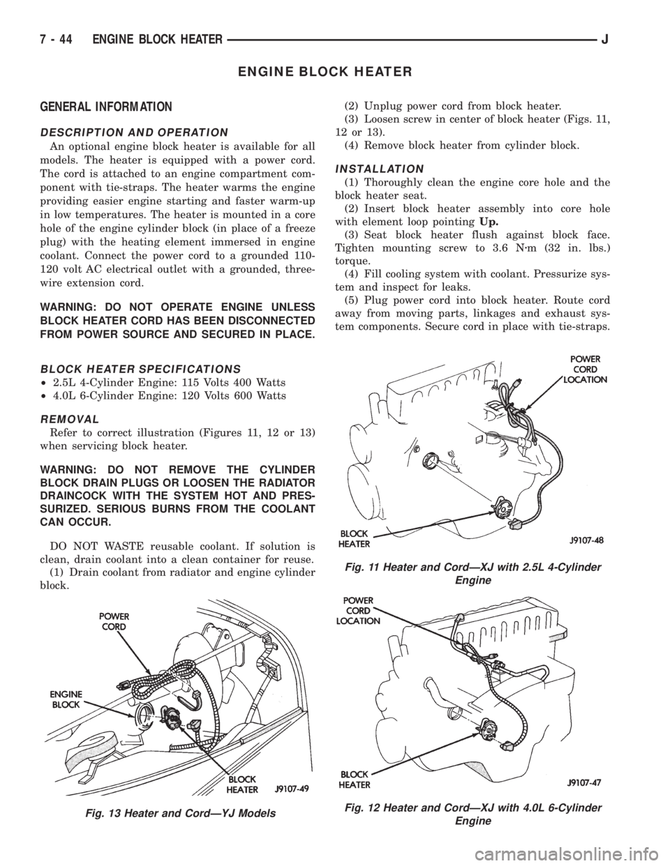
An optional engine block heater is available for all
models. The heater is equipped with a power cord.
The cord is attached to an engine compartment com-
ponent with tie-straps. The heater warms the engine
providing easier engine starting and faster warm-up
in low temperatures. The heater is mounted in a core
hole of the engine cylinder block (in place of a freeze
plug) with the heating element immersed in engine
coolant. Connect the power cord to a grounded 110-
120 volt AC electrical outlet with a grounded, three-
wire extension cord.
WARNING: DO NOT OPERATE ENGINE UNLESS
BLOCK HEATER CORD HAS BEEN DISCONNECTED
FROM POWER SOURCE AND SECURED IN PLACE.
BLOCK HEATER SPECIFICATIONS
²2.5L 4-Cylinder Engine: 115 Volts 400 Watts
²4.0L 6-Cylinder Engine: 120 Volts 600 Watts
REMOVAL
Refer to correct illustration (Figures 11, 12 or 13)
when servicing block heater.
WARNING: DO NOT REMOVE THE CYLINDER
BLOCK DRAIN PLUGS OR LOOSEN THE RADIATOR
DRAINCOCK WITH THE SYSTEM HOT AND PRES-
SURIZED. SERIOUS BURNS FROM THE COOLANT
CAN OCCUR.
DO NOT WASTE reusable coolant. If solution is
clean, drain coolant into a clean container for reuse.
(1) Drain coolant from radiator and engine cylinder
block.(2) Unplug power cord from block heater.
(3) Loosen screw in center of block heater (Figs. 11,
12 or 13).
(4) Remove block heater from cylinder block.
INSTALLATION
(1) Thoroughly clean the engine core hole and the
block heater seat.
(2) Insert block heater assembly into core hole
with element loop pointingUp.
(3) Seat block heater flush against block face.
Tighten mounting screw to 3.6 Nzm (32 in. lbs.)
torque.
(4) Fill cooling system with coolant. Pressurize sys-
tem and inspect for leaks.
(5) Plug power cord into block heater. Route cord
away from moving parts, linkages and exhaust sys-
tem components. Secure cord in place with tie-straps.
Fig. 13 Heater and CordÐYJ Models
Fig. 11 Heater and CordÐXJ with 2.5L 4-Cylinder
Engine
Fig. 12 Heater and CordÐXJ with 4.0L 6-Cylinder
Engine
7 - 44 ENGINE BLOCK HEATERJ
Page 296 of 2158

STARTING SYSTEM
GENERAL INFORMATION
The starting system (Fig. 1) consists of:
²ignition switch
²starter relay
²park/neutral position switch (automatic transmis-
sion)
²wiring harness and connections
²battery
²starter with an integral solenoid.
Following is a general description of the major
starting system components. Refer to Group 8W -
Wiring Diagrams for complete circuit descriptions
and diagrams.
These components form 2 separate circuits. A high-
amperage feed circuit that feeds the starter up to
300+ amps, and a low-amperage control circuit that
operates on less than 20 amps.
Battery voltage is supplied through the low-amper-
age control circuit to the coil battery terminal of the
starter relay when the ignition switch is turned to
the START position.
If the vehicle is equipped with an automatic trans-
mission, the park/neutral position switch provides a
ground path to the starter relay coil ground terminal.
This switch provides ground only with the transmis-
sion in NEUTRAL or PARK. If the vehicle is
equipped with a manual transmission, the starter re-
lay coil ground terminal is always grounded.
With the starter relay coil now energized, the nor-
mally open relay contacts close. The relay contacts
connect the relay common feed terminal to the relay
normally open terminal. The closed relay contacts en-
ergize the starter solenoid coil windings.
The energized solenoid coils pull-in and hold-in the
solenoid plunger. The solenoid plunger pulls the shiftlever in the starter. This engages the starter overrun-
ning clutch and pinion gear with the flywheel/drive
plate ring gear.
As the solenoid plunger reaches the end of its
travel, the solenoid contact disc completes the high-
amperage starter feed circuit. Current now flows be-
tween the solenoid battery terminal and the starter
motor, energizing the starter.
Once the engine starts, the overrunning clutch pro-
tects the starter from damage by allowing the starter
pinion gear to spin faster than the pinion shaft.
When the driver releases the ignition switch to the
ON position the starter relay coil is de-energized.
This causes the relay contacts to open. When the re-
lay contacts open, the starter solenoid coil is de-ener-
gized.
When the solenoid coil is de-energized, the solenoid
plunger return spring returns the plunger to its re-
laxed position. This causes the contact disc to open
the starter feed circuit, and the shift lever to disen-
gage the overrunning clutch and pinion gear from the
ring gear.
The starter motor and solenoid are serviced only as
a complete assembly. If either component fails, the
entire assembly must be replaced.
DIAGNOSIS
Before removing any unit from the starting system
for repair, perform the following inspections:
INSPECTION
BATTERY INSPECTION
To determine condition of the battery, see Battery
in this group.
WIRING INSPECTION
Inspect wiring for damage. Inspect all connections
at:
²starter solenoid
²park/neutral position switch (automatic transmis-
sion)
²ignition switch
²starter relay
²battery (including all ground connections).
Clean, tighten and repair all connections as re-
quired.
SOLENOID, RELAY AND SWITCH INSPECTIONS
Inspect the solenoid, relay and ignition switch to
determine their condition. Also, if equipped with au-
tomatic transmission, inspect condition of the park/
neutral position switch. Testing information can be
found in the following pages.
Fig. 1 Starting System Components (Typical)
JBATTERY/STARTING/CHARGING SYSTEMS DIAGNOSTICS 8A - 11
Page 299 of 2158

(4) Connect voltmeter to measure between the bat-
tery negative post and a good clean ground on the
engine block (Fig. 5). Rotate and hold ignition switch
in the START position. Observe voltmeter. If voltage
reads above 0.2 volt, correct poor contact at battery
negative cable attaching point. Repeat test. If read-
ing is still above 0.2 volt, replace battery negative ca-
ble.
(5) Connect positive lead of voltmeter to starter
housing. Connect negative lead of voltmeter to bat-
tery negative terminal (Fig. 6). Rotate and hold igni-
tion switch in the START position. Observe
voltmeter. If voltage reads above 0.2 volt, correct poor
starter to engine ground.
If resistance tests detect no feed circuit problems,
remove the starter and see Solenoid Test in this
group.
CONTROL CIRCUIT TESTS
The starter control circuit consists of:
²starter solenoid
²starter relay
²ignition switch
²park/neutral position switch (automatic transmis-
sion)²wiring harness and connections.
Test procedures for these components are as fol-
lows, and should be followed in the order described.
CAUTION: Before performing any test, unplug Auto
Shut-Down (ASD) relay from Power Distribution
Center (PDC) to prevent engine from starting.
SOLENOID TEST
Refer to Group 8B - Battery/Starter/Generator Ser-
vice for starter removal procedures.
(1) Disconnect solenoid field coil wire from field
coil terminal.
(2) Check for continuity between solenoid terminal
and field coil terminal with a continuity tester. There
should be continuity (Fig. 7).
(3) Check for continuity between solenoid terminal
and solenoid case. There should be continuity (Fig.
8).
(4) If there is continuity, solenoid is good. If there
is no continuity in either test, solenoid has an open
circuit and is faulty. Replace starter assembly.
(5) Connect solenoid field coil wire to field coil ter-
minal.
(6) Install starter as described in Group 8B - Bat-
tery/Starter/Generator Service.
RELAY TEST
The starter relay is in the Power Distribution Cen-
ter (PDC)(Figs. 9 or 10). Refer to the underside of the
PDC cover for relay location.
Fig. 5 Test Ground Circuit Resistance
Fig. 6 Test Starter Ground (Typical)
Fig. 7 Continuity Test Between Solenoid Terminal
and Field Coil Terminal
Fig. 8 Continuity Test Between Solenoid Terminal
and Solenoid Case
8A - 14 BATTERY/STARTING/CHARGING SYSTEMS DIAGNOSTICSJ
Page 300 of 2158

Remove starter relay from PDC to perform the fol-
lowing tests:
(1) A relay in the de-energized position should
have continuity between terminals 87A and 30, and
no continuity between terminals 87 and 30. If OK, go
to next step. If not OK, replace faulty relay.
(2) Resistance between terminals 85 and 86 (elec-
tromagnet) should be 7565 ohms. If OK, go to next
step. If not OK, replace faulty relay.
(3) Connect a battery to terminals 85 and 86.
There should now be continuity between terminals
30 and 87, and no continuity between terminals 87A
and 30. If OK, go to Relay Circuit Test. If not OK,
replace faulty relay.
RELAY CIRCUIT TEST
(1) The common feed terminal (30) is connected to
battery voltage and should be hot at all times. If OK,
go to next step. If not OK, check circuit to fuse (F4
for YJ, F10 for XJ) in Power Distribution Center
(PDC). Repair as required.
(2) The normally closed terminal (87A) is con-
nected to terminal 30 in the de-energized position,
but is not used for this application. Go to next step.
(3) The normally open terminal (87) is connected to
the battery terminal (30) in the energized position.
This terminal supplies battery voltage to the starter
solenoid field coils. There should be continuity be-
tween cavity for relay terminal 87 and the starter so-
lenoid terminal at all times. If OK, go to next step. If
not OK, repair circuit to solenoid as required.
(4) The coil battery terminal (86) is connected to
the electromagnet in the relay. It is energized when
the ignition switch is in the START position. Check
for battery voltage at cavity for relay terminal 86with ignition switch in the START position. If OK, go
to next step. If not OK, refer to Group 8D - Ignition
Systems for testing and service of the ignition switch.
(5) The coil ground terminal (85) is connected to
the electromagnet in the relay. On vehicles with an
automatic transmission, it is grounded through the
park/neutral position switch. On vehicles with a
manual transmission, it is grounded at all times.
Check for continuity to ground at cavity for relay ter-
minal 85. If not OK and vehicle has manual trans-
mission, repair circuit as required. If not OK and
vehicle has automatic transmission, refer to Group
21 - Transmission and Transfer Case for testing and
service of the park/neutral position switch.
Fig. 9 Power Distribution CenterÐXJ
Fig. 10 Power Distribution CenterÐYJ
STARTER RELAY CONNECTIONS
JBATTERY/STARTING/CHARGING SYSTEMS DIAGNOSTICS 8A - 15
Page 302 of 2158

CHARGING SYSTEM
GENERAL INFORMATION
The charging system consists of:
²generator
²voltage regulator circuitry (within PCM)
²ignition switch
²battery
²generator warning lamp or voltmeter (depending
on vehicle equipment)
²wiring harness and connections.
Following is a general description of the major
charging system components. Refer to Group 8W -
Wiring Diagrams for complete circuit descriptions
and diagrams.
The charging system is turned on and off with the
ignition switch. When the ignition switch is turned to
the ON position, battery voltage is applied to the
generator rotor through one of the two field termi-
nals to produce a magnetic field. The generator is
driven by the engine through a serpentine belt and
pulley arrangement.
As the energized rotor begins to rotate within the
generator, the spinning magnetic field induces a cur-
rent into the windings of the stator coil. Once the
generator begins producing sufficient current, it also
provides the current needed to energize the rotor.
The wye (Y) type stator winding connections de-
liver the induced AC current to 3 positive and 3 neg-
ative diodes for rectification. From the diodes,
rectified DC current is delivered to the vehicle elec-
trical system through the generator battery and
ground terminals.
The amount of DC current produced by the gener-
ator is controlled by the generator voltage regulator
(field control) circuitry, contained within the Power-
train Control Module (PCM)(Fig. 1). This circuitry is
connected in series with the second rotor field termi-
nal and ground.
Voltage is regulated by cycling the ground path to
control the strength of the rotor magnetic field. The
generator voltage regulator circuitry monitors system
line voltage and ambient temperature. It then com-
pensates and regulates generator current output ac-
cordingly.
The generator is serviced only as a complete as-
sembly. If the generator fails for any reason, the en-
tire assembly must be replaced. The generator
voltage regulator (field control) circuitry can be ser-
viced only by replacing the entire PCM.
All vehicles are equipped with On-Board Diagnos-
tics (OBD). All OBD-sensed systems, including the
generator voltage regulator (field control) circuitry,
are monitored by the PCM. Each monitored circuit is
assigned a Diagnostic Trouble Code (DTC). The PCM
will store a DTC in electronic memory for any failureit detects. See Using On-Board Diagnostic System in
this group for more information.
DIAGNOSIS
When operating normally, the indicator lamp on
models with the base instrument cluster will light
when the ignition switch is turned to the ON or
START position. After the engine starts, the indicator
lamp goes off. With the engine running, the charge
indicator lamp should light only when there is a
problem in the charging system (base cluster only).
On models with a voltmeter, when the ignition
switch is turned to the ON position, battery potential
will register on the meter. During engine cranking a
lower voltage will appear on the meter. With the en-
gine running, a voltage reading higher than the first
reading (ignition in ON) should register.
The following procedures may be used to diagnose
the charging system if:
²the indicator or voltmeter do not operate properly
²an undercharged or overcharged battery condition
occurs.
Remember that an undercharged battery is often
caused by:
Fig. 1 Charging System Components (Typical)
JBATTERY/STARTING/CHARGING SYSTEMS DIAGNOSTICS 8A - 17