1995 JEEP YJ transmission fluid
[x] Cancel search: transmission fluidPage 1680 of 2158
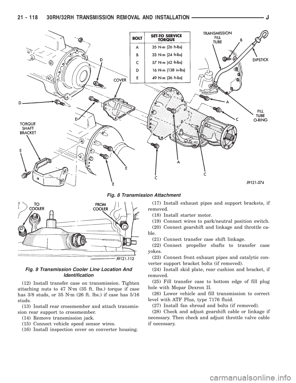
(12) Install transfer case on transmission. Tighten
attaching nuts to 47 Nzm (35 ft. lbs.) torque if case
has 3/8 studs, or 35 Nzm (26 ft. lbs.) if case has 5/16
studs.
(13) Install rear crossmember and attach transmis-
sion rear support to crossmember.
(14) Remove transmission jack.
(15) Connect vehicle speed sensor wires.
(16) Install inspection cover on converter housing.(17) Install exhaust pipes and support brackets, if
removed.
(18) Install starter motor.
(19) Connect wires to park/neutral position switch.
(20) Connect gearshift and linkage and throttle ca-
ble.
(21) Connect transfer case shift linkage.
(22) Connect propeller shafts to transfer case
yokes.
(23) Connect front exhaust pipes and catalytic con-
verter support bracket bolts (if removed).
(24) Install skid plate, rear cushion and bracket, if
removed.
(25) Fill transfer case to bottom edge of fill plug
hole with Mopar Dexron II.
(26) Lower vehicle and fill transmission to correct
level with ATF Plus, type 7176 fluid.
(27) Install fan shroud and bolts (if removed).
(28) Check and adjust gearshift cable or linkage if
necessary. Then check and adjust throttle valve cable
if necessary.
Fig. 8 Transmission Attachment
Fig. 9 Transmission Cooler Line Location And
Identification
21 - 118 30RH/32RH TRANSMISSION REMOVAL AND INSTALLATIONJ
Page 1687 of 2158
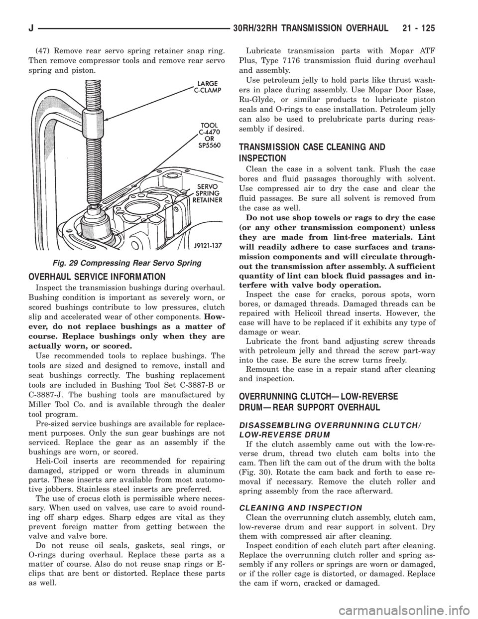
(47) Remove rear servo spring retainer snap ring.
Then remove compressor tools and remove rear servo
spring and piston.
OVERHAUL SERVICE INFORMATION
Inspect the transmission bushings during overhaul.
Bushing condition is important as severely worn, or
scored bushings contribute to low pressures, clutch
slip and accelerated wear of other components.How-
ever, do not replace bushings as a matter of
course. Replace bushings only when they are
actually worn, or scored.
Use recommended tools to replace bushings. The
tools are sized and designed to remove, install and
seat bushings correctly. The bushing replacement
tools are included in Bushing Tool Set C-3887-B or
C-3887-J. The bushing tools are manufactured by
Miller Tool Co. and is available through the dealer
tool program.
Pre-sized service bushings are available for replace-
ment purposes. Only the sun gear bushings are not
serviced. Replace the gear as an assembly if the
bushings are worn, or scored.
Heli-Coil inserts are recommended for repairing
damaged, stripped or worn threads in aluminum
parts. These inserts are available from most automo-
tive jobbers. Stainless steel inserts are preferred.
The use of crocus cloth is permissible where neces-
sary. When used on valves, use care to avoid round-
ing off sharp edges. Sharp edges are vital as they
prevent foreign matter from getting between the
valve and valve bore.
Do not reuse oil seals, gaskets, seal rings, or
O-rings during overhaul. Replace these parts as a
matter of course. Also do not reuse snap rings or E-
clips that are bent or distorted. Replace these parts
as well.Lubricate transmission parts with Mopar ATF
Plus, Type 7176 transmission fluid during overhaul
and assembly.
Use petroleum jelly to hold parts like thrust wash-
ers in place during assembly. Use Mopar Door Ease,
Ru-Glyde, or similar products to lubricate piston
seals and O-rings to ease installation. Petroleum jelly
can also be used to prelubricate parts during reas-
sembly if desired.
TRANSMISSION CASE CLEANING AND
INSPECTION
Clean the case in a solvent tank. Flush the case
bores and fluid passages thoroughly with solvent.
Use compressed air to dry the case and clear the
fluid passages. Be sure all solvent is removed from
the case as well.
Do not use shop towels or rags to dry the case
(or any other transmission component) unless
they are made from lint-free materials. Lint
will readily adhere to case surfaces and trans-
mission components and will circulate through-
out the transmission after assembly. A sufficient
quantity of lint can block fluid passages and in-
terfere with valve body operation.
Inspect the case for cracks, porous spots, worn
bores, or damaged threads. Damaged threads can be
repaired with Helicoil thread inserts. However, the
case will have to be replaced if it exhibits any type of
damage or wear.
Lubricate the front band adjusting screw threads
with petroleum jelly and thread the screw part-way
into the case. Be sure the screw turns freely.
Remount the case in a repair stand after cleaning
and inspection.
OVERRUNNING CLUTCHÐLOW-REVERSE
DRUMÐREAR SUPPORT OVERHAUL
DISASSEMBLING OVERRUNNING CLUTCH/
LOW-REVERSE DRUM
If the clutch assembly came out with the low-re-
verse drum, thread two clutch cam bolts into the
cam. Then lift the cam out of the drum with the bolts
(Fig. 30). Rotate the cam back and forth to ease re-
moval if necessary. Remove the clutch roller and
spring assembly from the race afterward.
CLEANING AND INSPECTION
Clean the overrunning clutch assembly, clutch cam,
low-reverse drum and rear support in solvent. Dry
them with compressed air after cleaning.
Inspect condition of each clutch part after cleaning.
Replace the overrunning clutch roller and spring as-
sembly if any rollers or springs are worn or damaged,
or if the roller cage is distorted, or damaged. Replace
the cam if worn, cracked or damaged.
Fig. 29 Compressing Rear Servo Spring
J30RH/32RH TRANSMISSION OVERHAUL 21 - 125
Page 1692 of 2158
if damaged. Inspect the park gear for chipped or
worn gear teeth or damaged ring grooves. Replace
the gear, if damaged.
Check the teeth on the park gear for wear or dam-
age. Replace the gear if necessary. Inspect the metal
seal rings on the park gear hub. Replace the rings
only if severely worn, or broken.
Minor scratches, or burrs on governor components
can be cleaned up with oil-soaked crocus cloth. How-
ever, do not attempt to salvage components that are
severely worn or scored.
The governor valve is made of aluminum and
the output shaft has been spotfaced to accept
the valve. The aluminum valve must not be
used in prior transmissions. The valve can only
be used with an output shaft that has been
spotfaced for valve end clearance. In addition,
the governor body and output shaft must be
properly indexed during reassembly. Be sure to
index these components as described in the
Transmission Assembly and Adjustment proce-
dures.
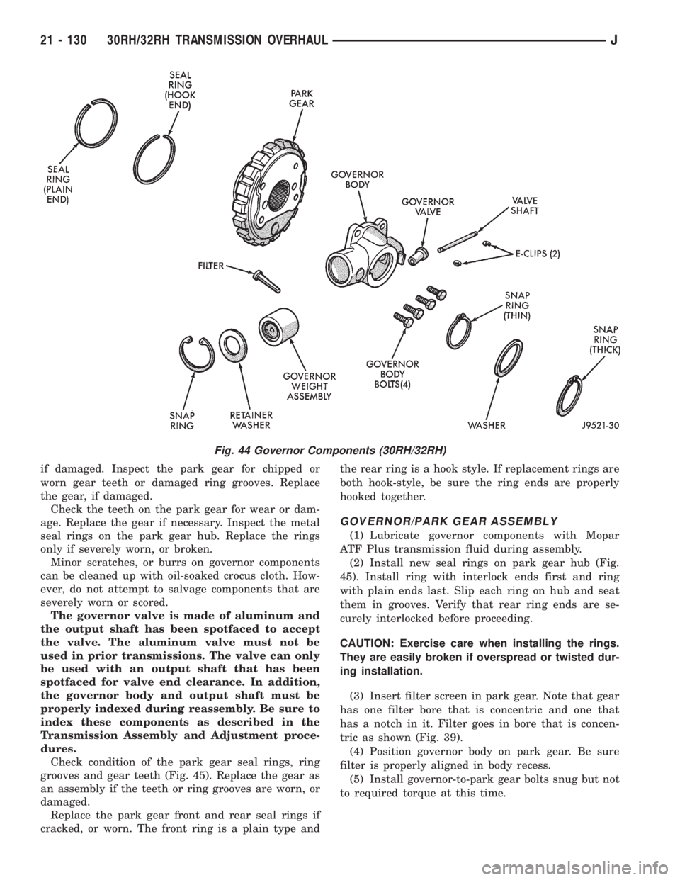
Check condition of the park gear seal rings, ring
grooves and gear teeth (Fig. 45). Replace the gear as
an assembly if the teeth or ring grooves are worn, or
damaged.
Replace the park gear front and rear seal rings if
cracked, or worn. The front ring is a plain type andthe rear ring is a hook style. If replacement rings are
both hook-style, be sure the ring ends are properly
hooked together.
GOVERNOR/PARK GEAR ASSEMBLY
(1) Lubricate governor components with Mopar
ATF Plus transmission fluid during assembly.
(2) Install new seal rings on park gear hub (Fig.
45). Install ring with interlock ends first and ring
with plain ends last. Slip each ring on hub and seat
them in grooves. Verify that rear ring ends are se-
curely interlocked before proceeding.
CAUTION: Exercise care when installing the rings.
They are easily broken if overspread or twisted dur-
ing installation.
(3) Insert filter screen in park gear. Note that gear
has one filter bore that is concentric and one that
has a notch in it. Filter goes in bore that is concen-
tric as shown (Fig. 39).
(4) Position governor body on park gear. Be sure
filter is properly aligned in body recess.
(5) Install governor-to-park gear bolts snug but not
to required torque at this time.
Fig. 44 Governor Components (30RH/32RH)
21 - 130 30RH/32RH TRANSMISSION OVERHAULJ
Page 1695 of 2158
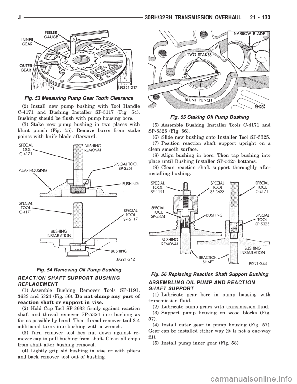
(2) Install new pump bushing with Tool Handle
C-4171 and Bushing Installer SP-5117 (Fig. 54).
Bushing should be flush with pump housing bore.
(3) Stake new pump bushing in two places with
blunt punch (Fig. 55). Remove burrs from stake
points with knife blade afterward.
REACTION SHAFT SUPPORT BUSHING
REPLACEMENT
(1) Assemble Bushing Remover Tools SP-1191,
3633 and 5324 (Fig. 56).Do not clamp any part of
reaction shaft or support in vise.
(2) Hold Cup Tool SP-3633 firmly against reaction
shaft and thread remover SP-5324 into bushing as
far as possible by hand. Then thread remover tool 3-4
additional turns into bushing with a wrench.
(3) Turn remover tool hex nut down against re-
mover cup to pull bushing from shaft. Clean all chips
from shaft after bushing removal.
(4) Lightly grip old bushing in vise or with pliers
and back remover tool out of bushing.(5) Assemble Bushing Installer Tools C-4171 and
SP-5325 (Fig. 56).
(6) Slide new bushing onto Installer Tool SP-5325.
(7) Position reaction shaft support upright on a
clean smooth surface.
(8) Align bushing in bore. Then tap bushing into
place until Bushing Installer SP-5325 bottoms.
(9) Clean reaction shaft support thoroughly after
installing bushing.
ASSEMBLING OIL PUMP AND REACTION
SHAFT SUPPORT
(1) Lubricate gear bore in pump housing with
transmission fluid.
(2) Lubricate pump gears with transmission fluid.
(3) Support pump housing on wood blocks (Fig.
57).
(4) Install outer gear in pump housing (Fig. 57).
Gear can be installed either way (it is not a one-way
fit).
(5) Install pump inner gear (Fig. 58).
Fig. 53 Measuring Pump Gear Tooth Clearance
Fig. 54 Removing Oil Pump Bushing
Fig. 55 Staking Oil Pump Bushing
Fig. 56 Replacing Reaction Shaft Support Bushing
J30RH/32RH TRANSMISSION OVERHAUL 21 - 133
Page 1696 of 2158

CAUTION: The pump inner gear is a one way fit.
The bore on one side of the gear inside diameter
(I.D.) is chamfered. Be sure the chamfered side
faces forward (to front of pump).
(6) Install new thrust washer on hub of reaction
shaft support. Lubricate washer with transmission
fluid or petroleum jelly.
(7) If reaction shaft seal rings are being replaced,
install new seal rings on support hub (Fig. 59). Lu-
bricate seal rings with transmission fluid or petro-
leum jelly after installation. Squeeze each ring until
ring ends are securely hooked together.
CAUTION: The reaction shaft support seal rings will
break if overspread, or twisted. If new rings are be-
ing installed, spread them only enough for installa-
tion. Also be very sure the ring ends are securely
hooked together after installation. Otherwise, the
rings will either prevent pump installation, or break
during installation.
(8) Install reaction shaft support on pump housing
(Fig. 60).(9) Align reaction support on pump housing. Use
alignment marks made at disassembly. Or, rotate
support until bolt holes in support and pump housing
are all aligned (holes are offset for one-way fit).
(10) Install all bolts that attach support to pump
housing. Then tighten bolts finger tight.
(11) Tighten support-to-pump bolts to required
torque as follows:
(a) Reverse pump assembly and install it in
transmission case. Position pump so bolts are fac-
ing out and are accessible.
(b) Secure pump assembly in case with 2 or 3
bolts, or with pilot studs.
(c) Tighten support-to-pump bolts to 20 Nzm (15
ft. lbs.).
(d) Remove pump assembly from transmission
case.
(12) Install new oil seal in pump with Special Tool
C-4193 and Tool Handle C-4171 (Fig. 61). Be sure
seal lip faces inward.
(13) Install new seal ring around pump housing.
Be sure seal is properly seated in groove.
(14) Lubricate lip of pump oil seal and O-ring seal
with transmission fluid.
FRONT CLUTCH OVERHAUL
FRONT CLUTCH DISASSEMBLY
(1) Remove waved snap ring and remove pressure
plate, clutch plates and clutch discs (Fig. 62).
Fig. 57 Supporting Pump And Installing Outer Gear
Fig. 58 Pump Inner Gear Installation
Fig. 59 Hub Seal Ring Position
Fig. 60 Assembling Reaction Shaft Support And
Pump Housing
21 - 134 30RH/32RH TRANSMISSION OVERHAULJ
Page 1697 of 2158
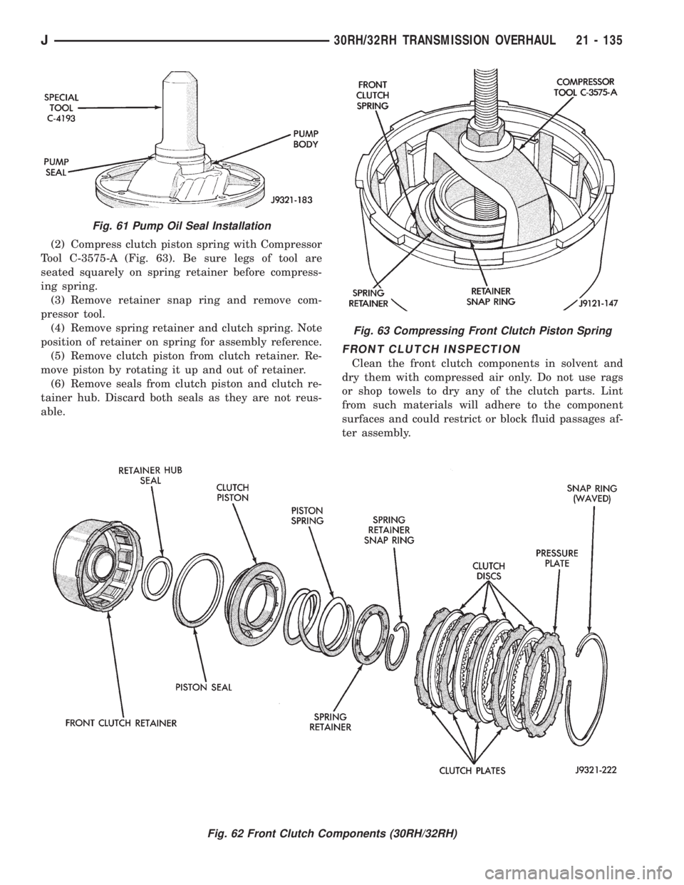
(2) Compress clutch piston spring with Compressor
Tool C-3575-A (Fig. 63). Be sure legs of tool are
seated squarely on spring retainer before compress-
ing spring.
(3) Remove retainer snap ring and remove com-
pressor tool.
(4) Remove spring retainer and clutch spring. Note
position of retainer on spring for assembly reference.
(5) Remove clutch piston from clutch retainer. Re-
move piston by rotating it up and out of retainer.
(6) Remove seals from clutch piston and clutch re-
tainer hub. Discard both seals as they are not reus-
able.
FRONT CLUTCH INSPECTION
Clean the front clutch components in solvent and
dry them with compressed air only. Do not use rags
or shop towels to dry any of the clutch parts. Lint
from such materials will adhere to the component
surfaces and could restrict or block fluid passages af-
ter assembly.
Fig. 63 Compressing Front Clutch Piston Spring
Fig. 62 Front Clutch Components (30RH/32RH)
Fig. 61 Pump Oil Seal Installation
J30RH/32RH TRANSMISSION OVERHAUL 21 - 135
Page 1698 of 2158
Replace the clutch discs if warped, worn, scored,
burned or charred, or if the facing is flaking off. Re-
place the steel plates if heavily scored, warped, or
broken. Be sure the driving lugs on the plates are in
good condition. The lugs must not be bent, cracked or
damaged in any way.
Replace the clutch spring and spring retainer if ei-
ther is distorted, warped or broken.
Check the lug grooves in the clutch retainer. The
steel plates should slide freely in the slots. Replace
the retainer if the grooves are worn or damaged.
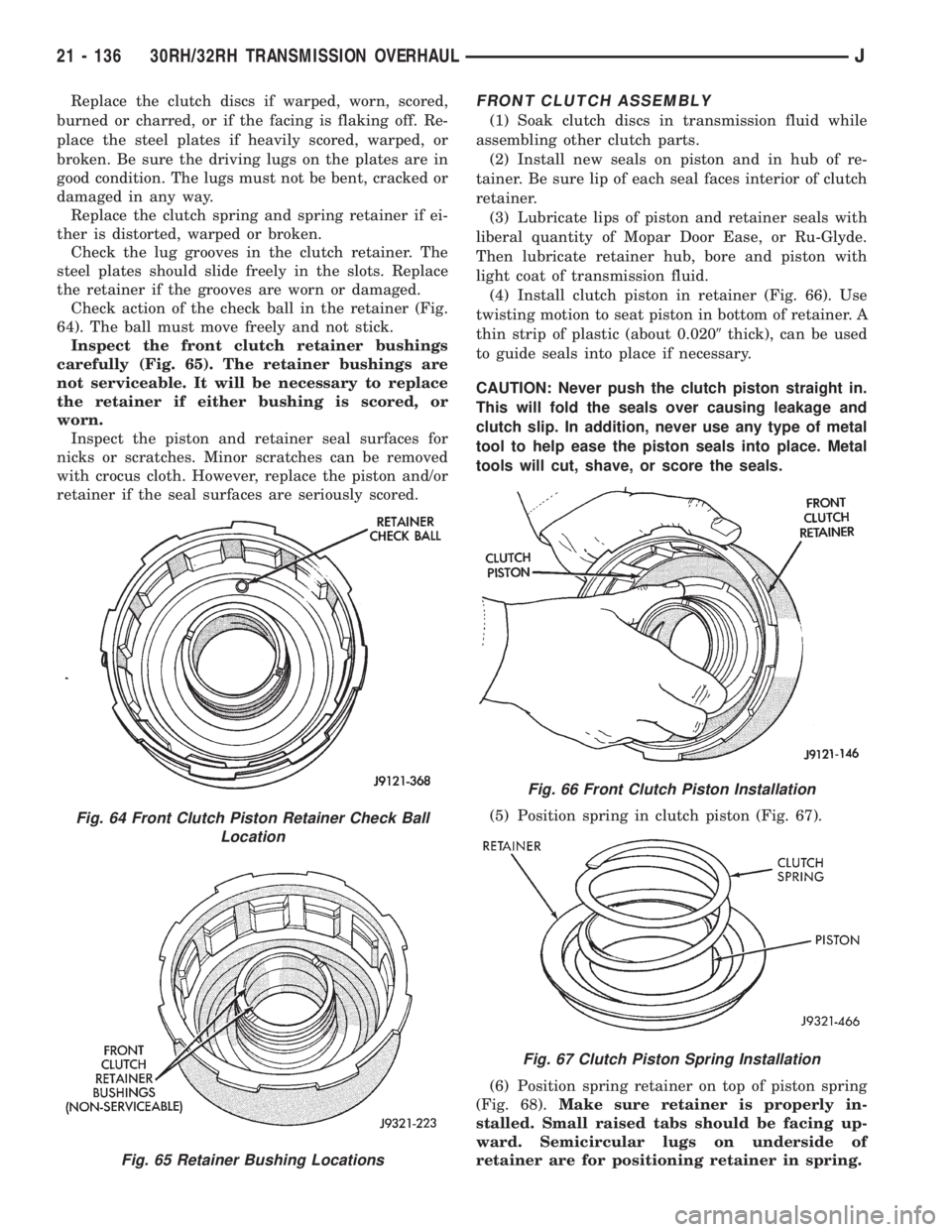
Check action of the check ball in the retainer (Fig.
64). The ball must move freely and not stick.
Inspect the front clutch retainer bushings
carefully (Fig. 65). The retainer bushings are
not serviceable. It will be necessary to replace
the retainer if either bushing is scored, or
worn.
Inspect the piston and retainer seal surfaces for
nicks or scratches. Minor scratches can be removed
with crocus cloth. However, replace the piston and/or
retainer if the seal surfaces are seriously scored.FRONT CLUTCH ASSEMBLY
(1) Soak clutch discs in transmission fluid while
assembling other clutch parts.
(2) Install new seals on piston and in hub of re-
tainer. Be sure lip of each seal faces interior of clutch
retainer.
(3) Lubricate lips of piston and retainer seals with
liberal quantity of Mopar Door Ease, or Ru-Glyde.
Then lubricate retainer hub, bore and piston with
light coat of transmission fluid.
(4) Install clutch piston in retainer (Fig. 66). Use
twisting motion to seat piston in bottom of retainer. A
thin strip of plastic (about 0.0209thick), can be used
to guide seals into place if necessary.
CAUTION: Never push the clutch piston straight in.
This will fold the seals over causing leakage and
clutch slip. In addition, never use any type of metal
tool to help ease the piston seals into place. Metal
tools will cut, shave, or score the seals.
(5) Position spring in clutch piston (Fig. 67).
(6) Position spring retainer on top of piston spring
(Fig. 68).Make sure retainer is properly in-
stalled. Small raised tabs should be facing up-
ward. Semicircular lugs on underside of
retainer are for positioning retainer in spring.
Fig. 64 Front Clutch Piston Retainer Check Ball
Location
Fig. 65 Retainer Bushing Locations
Fig. 66 Front Clutch Piston Installation
Fig. 67 Clutch Piston Spring Installation
21 - 136 30RH/32RH TRANSMISSION OVERHAULJ
Page 1700 of 2158
REAR CLUTCH OVERHAUL
REAR CLUTCH DISASSEMBLY
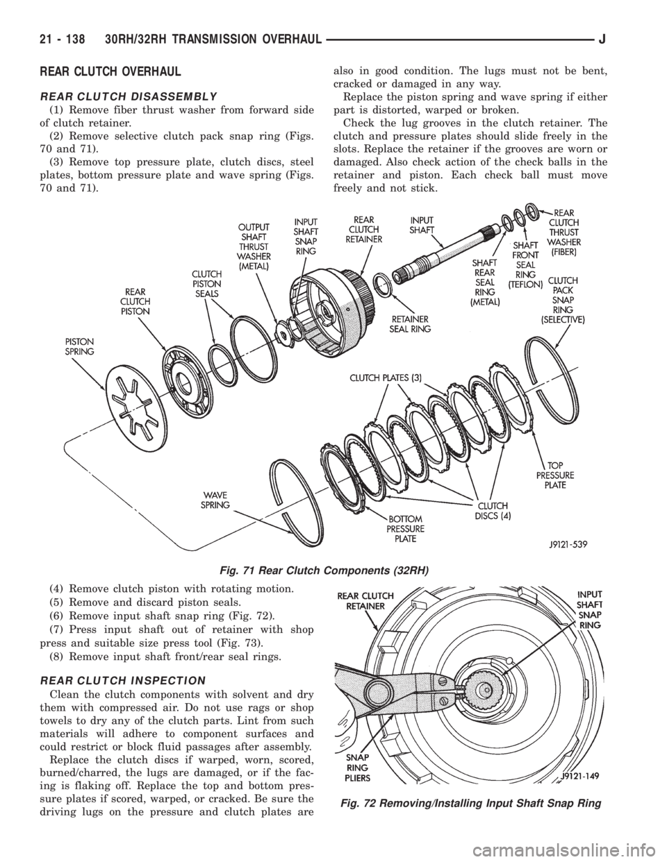
(1) Remove fiber thrust washer from forward side
of clutch retainer.
(2) Remove selective clutch pack snap ring (Figs.
70 and 71).
(3) Remove top pressure plate, clutch discs, steel
plates, bottom pressure plate and wave spring (Figs.
70 and 71).
(4) Remove clutch piston with rotating motion.
(5) Remove and discard piston seals.
(6) Remove input shaft snap ring (Fig. 72).
(7) Press input shaft out of retainer with shop
press and suitable size press tool (Fig. 73).
(8) Remove input shaft front/rear seal rings.
REAR CLUTCH INSPECTION
Clean the clutch components with solvent and dry
them with compressed air. Do not use rags or shop
towels to dry any of the clutch parts. Lint from such
materials will adhere to component surfaces and
could restrict or block fluid passages after assembly.
Replace the clutch discs if warped, worn, scored,
burned/charred, the lugs are damaged, or if the fac-
ing is flaking off. Replace the top and bottom pres-
sure plates if scored, warped, or cracked. Be sure the
driving lugs on the pressure and clutch plates arealso in good condition. The lugs must not be bent,
cracked or damaged in any way.
Replace the piston spring and wave spring if either
part is distorted, warped or broken.
Check the lug grooves in the clutch retainer. The
clutch and pressure plates should slide freely in the
slots. Replace the retainer if the grooves are worn or
damaged. Also check action of the check balls in the
retainer and piston. Each check ball must move
freely and not stick.
Fig. 71 Rear Clutch Components (32RH)
Fig. 72 Removing/Installing Input Shaft Snap Ring
21 - 138 30RH/32RH TRANSMISSION OVERHAULJ