1995 JEEP YJ frame
[x] Cancel search: framePage 1508 of 2158
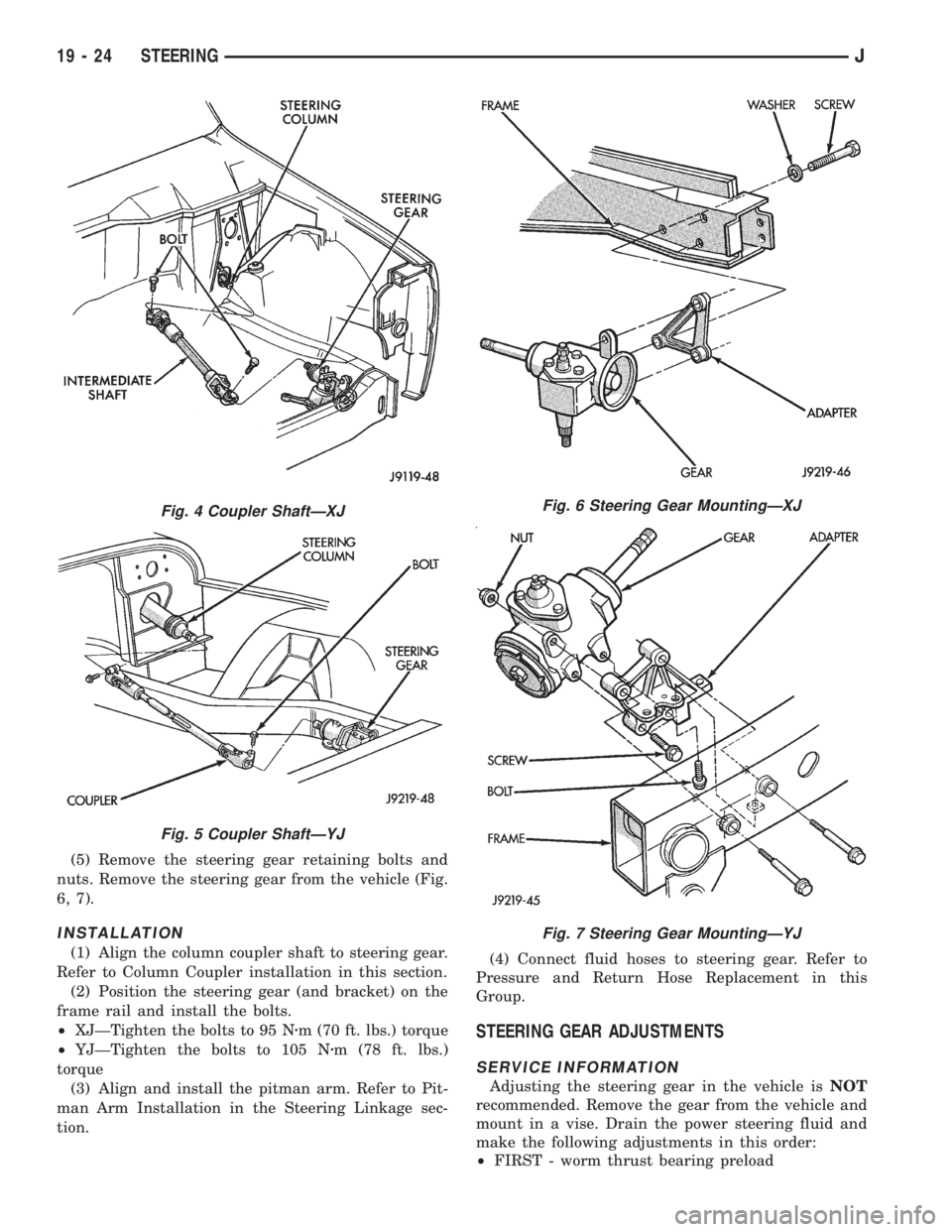
(5) Remove the steering gear retaining bolts and
nuts. Remove the steering gear from the vehicle (Fig.
6, 7).
INSTALLATION
(1) Align the column coupler shaft to steering gear.
Refer to Column Coupler installation in this section.
(2) Position the steering gear (and bracket) on the
frame rail and install the bolts.
²XJÐTighten the bolts to 95 Nzm (70 ft. lbs.) torque
²YJÐTighten the bolts to 105 Nzm (78 ft. lbs.)
torque
(3) Align and install the pitman arm. Refer to Pit-
man Arm Installation in the Steering Linkage sec-
tion.(4) Connect fluid hoses to steering gear. Refer to
Pressure and Return Hose Replacement in this
Group.
STEERING GEAR ADJUSTMENTS
SERVICE INFORMATION
Adjusting the steering gear in the vehicle isNOT
recommended. Remove the gear from the vehicle and
mount in a vise. Drain the power steering fluid and
make the following adjustments in this order:
²FIRST - worm thrust bearing preload
Fig. 4 Coupler ShaftÐXJ
Fig. 5 Coupler ShaftÐYJ
Fig. 6 Steering Gear MountingÐXJ
Fig. 7 Steering Gear MountingÐYJ
19 - 24 STEERINGJ
Page 1529 of 2158
(4) Hold pitman shaft adjustment screw and
tighten adjuster lock nut to 34 Nzm (25 ft. lbs.)
torque.
INTERMEDIATE (COUPLER) SHAFT
REMOVAL
(1) Place the front wheels in the straight ahead po-
sition.
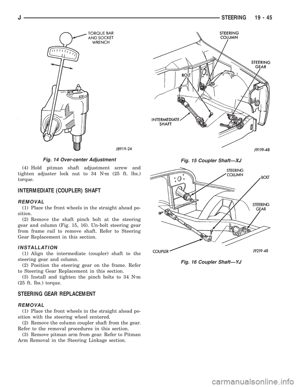
(2) Remove the shaft pinch bolt at the steering
gear and column (Fig. 15, 16). Un-bolt steering gear
from frame rail to remove shaft. Refer to Steering
Gear Replacement in this section.
INSTALLATION
(1) Align the intermediate (coupler) shaft to the
steering gear and column.
(2) Position the steering gear on the frame. Refer
to Steering Gear Replacement in this section.
(3) Install and tighten the pinch bolts to 34 Nzm
(25 ft. lbs.) torque.
STEERING GEAR REPLACEMENT
REMOVAL
(1) Place the front wheels in the straight ahead po-
sition with the steering wheel centered.
(2) Remove the column coupler shaft from the gear.
Refer to the removal procedures in this section.
(3) Remove pitman arm from gear. Refer to Pitman
Arm Removal in the Steering Linkage section.
Fig. 14 Over-center AdjustmentFig. 15 Coupler ShaftÐXJ
Fig. 16 Coupler ShaftÐYJ
JSTEERING 19 - 45
Page 1530 of 2158
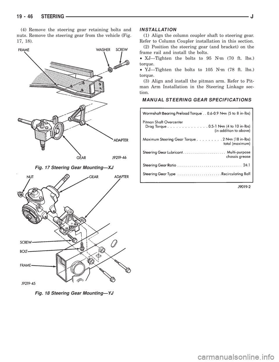
(4) Remove the steering gear retaining bolts and
nuts. Remove the steering gear from the vehicle (Fig.
17, 18).INSTALLATION
(1) Align the column coupler shaft to steering gear.
Refer to Column Coupler installation in this section.
(2) Position the steering gear (and bracket) on the
frame rail and install the bolts.
²XJÐTighten the bolts to 95 Nzm (70 ft. lbs.)
torque.
²YJÐTighten the bolts to 105 Nzm (78 ft. lbs.)
torque.
(3) Align and install the pitman arm. Refer to Pit-
man Arm Installation in the Steering Linkage sec-
tion.
Fig. 17 Steering Gear MountingÐXJ
Fig. 18 Steering Gear MountingÐYJ
MANUAL STEERING GEAR SPECIFICATIONS
19 - 46 STEERINGJ
Page 1567 of 2158
(21) Remove clutch release bearing, release fork
and retainer clip.
(22) Remove clutch housing from transmission.
TRANSMISSION INSTALLATION
(1) Install clutch housing on transmission. Tighten
housing bolts to 37 Nzm (27 ft. lbs.) torque.
(2) Lubricate contact surfaces of release fork pivot
ball stud and release fork with high temp grease.
Then install release bearing, fork and retainer clip.
(3) Mount transmission on transmission jack.
(4) Lightly lubricate pilot bearing and transmis-
sion input shaft splines with Mopar high temp
grease.
(5) Align transmission input shaft, release bearing,
and clutch disc splines. Then slide transmission into
place.
(6) Install and tighten clutch housing-to-engine
bolts to 38 Nzm (28 ft. lbs.) torque.Be sure the
housing is properly seated on engine block be-
fore tightening bolts.
(7) Lower transmission approximately 7-8 cm (3
in.) for access to shift tower. Be sure transmission is
in first or third gear.
(8) Reach up and around transmission and insert
shift lever in shift tower. Press lever retainer down-
ward and turn it clockwise to lock it in place. Then
install lever dust boot on shift tower.
(9) Install slave cylinder in clutch housing.
(10) Align and install transfer case on and trans-
mission. Tighten transfer case-to-transmission nuts
to 35 Nzm (26 ft. lbs.) torque.
(11) Connect transfer case vent hose and shift link-
age. Check and adjust linkage if necessary.
(12) Connect transfer case vent hose.
(13) Secure wire harnesses in clips/tie straps on
transmission and transfer case.
(14) Connect backup light switch wires.
(15) Connect vehicle speed sensor wires.
(16) Install and connect crankshaft position sensor.
(17) Install rear crossmember (Fig. 5). On XJ,
tighten crossmember-to-frame bolts to 41 Nzm (31 ft.
lbs.) torque. Then tighten transmission-to-rear sup-
port bolts/nuts to 45 Nzm (33 ft. lbs.) torque. On YJ,
tighten bolts/nuts to indicated torque (Fig. 5).
(18) Remove jack stand.
(19) Align and install front/rear propeller shafts.
Tighten shaft U-joint clamp bolts to 19 Nzm (170 in.
lbs.) torque.
(20) Install skid plate, if equipped. Tighten bolts to
42 Nzm (31 ft. lbs.) torque. Tighten stud nuts to 17
Nzm (150 in. lbs.) torque.
(21) Top off transmission and transfer case lubri-
cant levels.
(22) Lower vehicle.
TRANSMISSION DISASSEMBLY AND OVERHAUL
ADAPTER HOUSING AND FRONT BEARING
RETAINER REMOVAL
(1) Drain transmission lubricant.
(2) Remove release bearing and lever.
(3) Remove clutch housing bolts and remove hous-
ing.
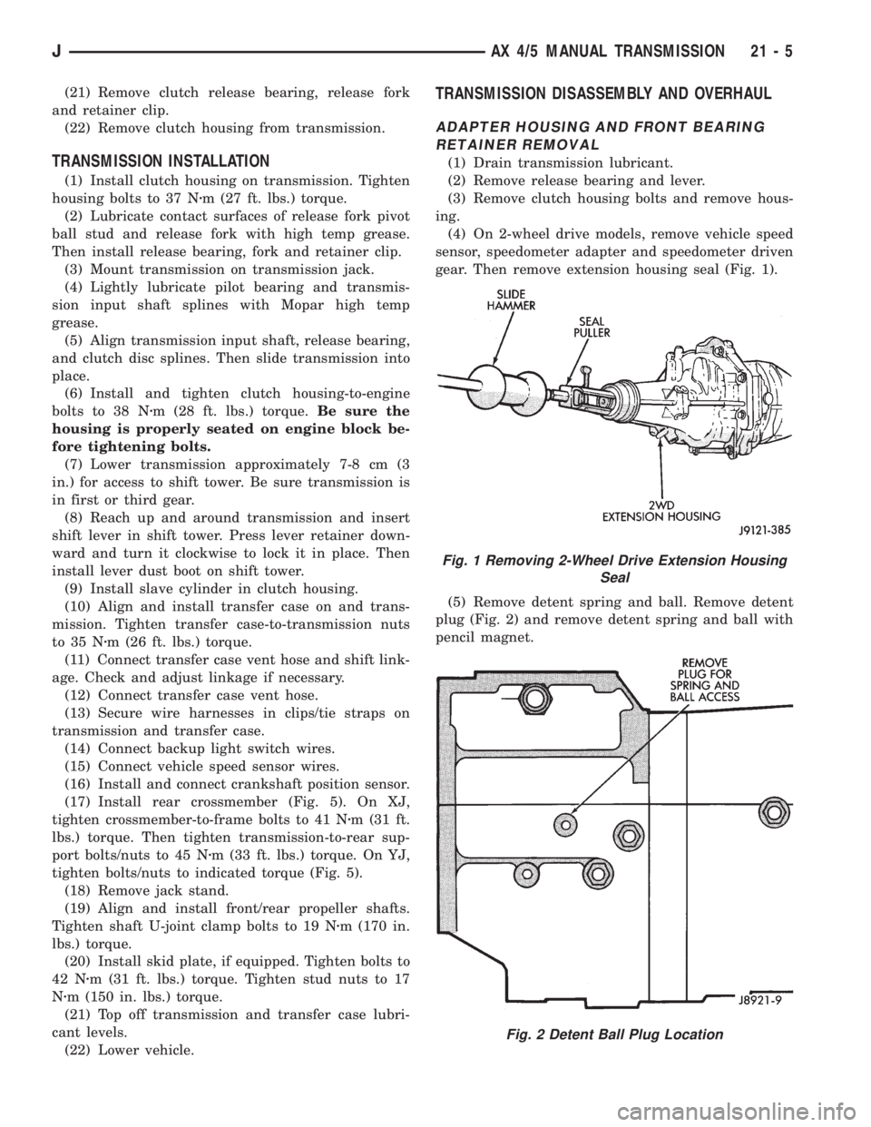
(4) On 2-wheel drive models, remove vehicle speed
sensor, speedometer adapter and speedometer driven
gear. Then remove extension housing seal (Fig. 1).
(5) Remove detent spring and ball. Remove detent
plug (Fig. 2) and remove detent spring and ball with
pencil magnet.
Fig. 1 Removing 2-Wheel Drive Extension Housing
Seal
Fig. 2 Detent Ball Plug Location
JAX 4/5 MANUAL TRANSMISSION 21 - 5
Page 1599 of 2158
(6) Install and tighten clutch housing-to-engine
bolts to 38 Nzm (28 ft. lbs.) torque.Be sure housing
is properly seated on engine before tightening
bolts.
(7) Lower transmission no more than 7.6 cm (3 in.)
for access to the shift tower.
(8) Reach up and around the transmission and in-
sert shift lever in shift tower. Press lever retainer
downward and turn it clockwise to lock it in place.
Then install lever dust boot on shift tower.
(9) Install and connect crankshaft position sensor.
(10) Align and install transfer case on transmis-
sion. Tighten transfer case attaching nuts to 35 Nzm
(26 ft. lbs.) torque.
(11) Connect transfer case vacuum and vent hoses.
(12) Install and connect transfer case shift linkage.
Check and adjust linkage if necessary.
(13) Secure wire harnesses to clips/tie straps on
transmission and transfer case.
(14) Connect backup light switch wires.
(15) Install clutch slave cylinder.
(16) Connect vehicle speed sensor wires.
(17) On XJ, install rear crossmember and attach
cushion and bracket. Tighten crossmember-to-frame
bolts to 41 Nzm (30 ft. lbs.) torque. Tighten transmis-
sion-to-rear cushion and bracket bolts/nuts to 45 Nzm
(33 ft. lbs.) torque.
(18) On YJ, install rear cushion and bracket and
skid plate. Tighten attaching bolts/nuts to indicated
torque (Fig. 1).
(19) Align and install front/rear propeller shafts.
Tighten shaft U-joint clamp bolts to 19 Nzm (170 in.
lbs.) torque.
(20) On XJ, install skid plate if removed. Tighten
bolts to 42 Nzm (31 ft. lbs.) torque. Tighten stud nuts
to 17 Nzm (150 in. lbs.) torque.
(21) Top off transmission and transfer lubricant
levels.
(22) Remove supports and lower vehicle.
TRANSMISSION DISASSEMBLY AND OVERHAUL
ADAPTER HOUSING REMOVAL
(1) Remove release bearing, release lever and re-
lease fork from clutch housing. Then remove clutch
housing from transmission.
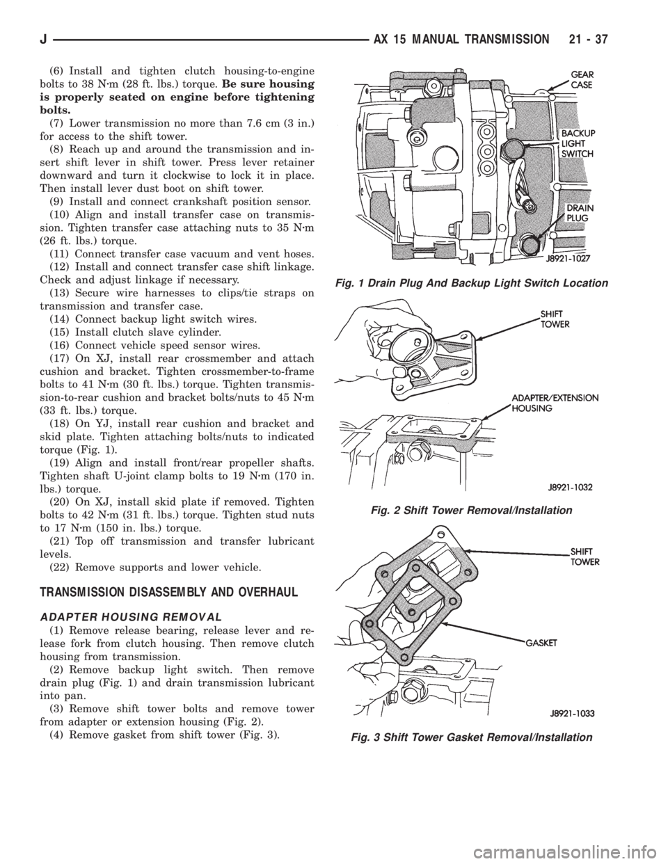
(2) Remove backup light switch. Then remove
drain plug (Fig. 1) and drain transmission lubricant
into pan.
(3) Remove shift tower bolts and remove tower
from adapter or extension housing (Fig. 2).
(4) Remove gasket from shift tower (Fig. 3).
Fig. 1 Drain Plug And Backup Light Switch Location
Fig. 2 Shift Tower Removal/Installation
Fig. 3 Shift Tower Gasket Removal/Installation
JAX 15 MANUAL TRANSMISSION 21 - 37
Page 1677 of 2158
30RH/32RH TRANSMISSION REMOVAL AND INSTALLATION
INDEX
page page
ConverterÐPump SealÐDrive Plate Service.... 116
Transmission and Converter Installation........ 117Transmission and Converter Removal......... 115
TRANSMISSION AND CONVERTER REMOVAL
(1) Remove fan shroud attaching bolts.
(2) Disconnect transmission fill tube at upper
bracket.
(3) Raise vehicle.
(4) Remove inspection cover from converter hous-
ing and remove skid plate for access, if necessary.
(5) Remove transmission fill tube and fill tube O-
ring.
(6) Remove starter motor.
(7) Mark propeller shafts and axle yokes for align-
ment reference.
(8) Disconnect propeller shafts at yokes. Secure
shafts to frame rails with wire.
(9) Disconnect exhaust pipes at exhaust manifolds,
if necessary.
(10) Drain transfer case lubricant, if transfer case
will also be serviced.
(11) Disconnect vehicle speed sensor wires.
(12) Disconnect transfer case shift linkage.
(13) Disconnect gearshift cable/linkage and throttle
valve cable at transmission levers.
(14) Disconnect transfer case vent hose. Then dis-
connect indicator switch wires on XJ, or vacuum
switch harness on YJ.
(15) Remove wire harness from clips on transfer
case.
(16) Remove transfer case attaching nuts and re-
move transfer case. Use transmission jack or helper
to support and remove transfer case.
(17) Disconnect park/neutral position switch wires.
(18) Disconnect and remove crankshaft position
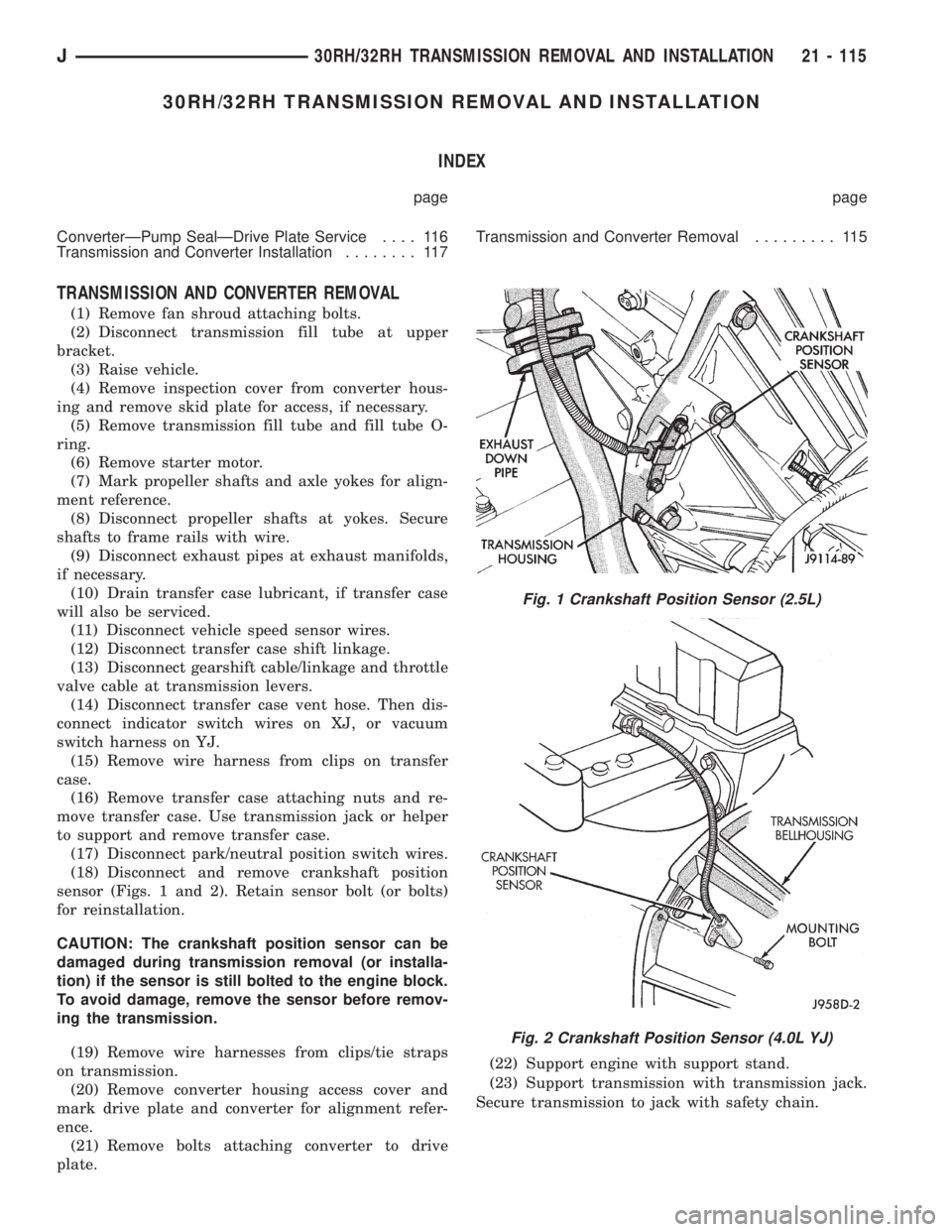
sensor (Figs. 1 and 2). Retain sensor bolt (or bolts)
for reinstallation.
CAUTION: The crankshaft position sensor can be
damaged during transmission removal (or installa-
tion) if the sensor is still bolted to the engine block.
To avoid damage, remove the sensor before remov-
ing the transmission.
(19) Remove wire harnesses from clips/tie straps
on transmission.
(20) Remove converter housing access cover and
mark drive plate and converter for alignment refer-
ence.
(21) Remove bolts attaching converter to drive
plate.(22) Support engine with support stand.
(23) Support transmission with transmission jack.
Secure transmission to jack with safety chain.
Fig. 1 Crankshaft Position Sensor (2.5L)
Fig. 2 Crankshaft Position Sensor (4.0L YJ)
J30RH/32RH TRANSMISSION REMOVAL AND INSTALLATION 21 - 115
Page 1944 of 2158
(3) Pull downward and remove the grille from ex-
haust port in the door opening panel.
INSTALLATION
(1) Position the slot located in the upper end of re-
placement grille at the exhaust port and insert edge
in the slot.
(2) Push inward and seat the grille in the exhaust
port.
(3) Install the screw to attach the grille to the door
opening panel.
EXTERIOR NAMEPLATESÐXJ
SERVICE INFORMATION
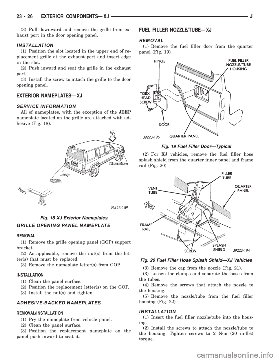
All of nameplates, with the exception of the JEEP
nameplate located on the grille are attached with ad-
hesive (Fig. 18).
GRILLE OPENING PANEL NAMEPLATE
REMOVAL
(1) Remove the grille opening panel (GOP) support
bracket.
(2) As applicable, remove the nut(s) from the let-
ter(s) that must be replaced.
(3) Remove the nameplate letter(s) from GOP.
INSTALLATION
(1) Clean the panel surface.
(2) Position the replacement letter(s) on the GOP.
(3) Install the nut(s) and tighten.
ADHESIVE-BACKED NAMEPLATES
REMOVAL/INSTALLATION
(1) Pry the nameplate from vehicle panel.
(2) Clean the panel surface.
(3) Position the replacement nameplate on the
panel push inward to seat it.
FUEL FILLER NOZZLE/TUBEÐXJ
REMOVAL
(1) Remove the fuel filler door from the quarter
panel (Fig. 19).
(2) For XJ vehicles, remove the fuel filler hose
splash shield from the quarter inner panel and frame
rail (Fig. 20).
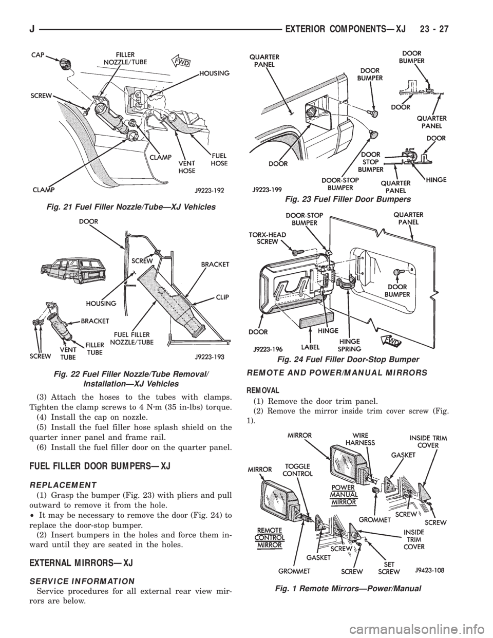
(3) Remove the cap from the nozzle (Fig. 21).
(3) Loosen the clamps and separate the hoses from
the tubes.
(4) Remove the screws that attach the nozzle to
the housing.
(5) Remove the nozzle/tube from the fuel filler
housing (Fig. 22).
INSTALLATION
(1) Insert the fuel filler nozzle/tube into the hous-
ing.
(2) Install the screws to attach the nozzle/tube to
the housing. Tighten screws to 2 Nzm (20 in-lbs)
torque.
Fig. 18 XJ Exterior Nameplates
Fig. 19 Fuel Filler DoorÐTypical
Fig. 20 Fuel Filler Hose Splash ShieldÐXJ Vehicles
23 - 26 EXTERIOR COMPONENTSÐXJJ
Page 1945 of 2158
(3) Attach the hoses to the tubes with clamps.
Tighten the clamp screws to 4 Nzm (35 in-lbs) torque.
(4) Install the cap on nozzle.
(5) Install the fuel filler hose splash shield on the
quarter inner panel and frame rail.
(6) Install the fuel filler door on the quarter panel.
FUEL FILLER DOOR BUMPERSÐXJ
REPLACEMENT
(1) Grasp the bumper (Fig. 23) with pliers and pull
outward to remove it from the hole.
²It may be necessary to remove the door (Fig. 24) to
replace the door-stop bumper.
(2) Insert bumpers in the holes and force them in-
ward until they are seated in the holes.
EXTERNAL MIRRORSÐXJ
SERVICE INFORMATION
Service procedures for all external rear view mir-
rors are below.
REMOTE AND POWER/MANUAL MIRRORS
REMOVAL
(1) Remove the door trim panel.
(2) Remove the mirror inside trim cover screw (Fig.
1).
Fig. 21 Fuel Filler Nozzle/TubeÐXJ Vehicles
Fig. 22 Fuel Filler Nozzle/Tube Removal/
InstallationÐXJ Vehicles
Fig. 23 Fuel Filler Door Bumpers
Fig. 24 Fuel Filler Door-Stop Bumper
Fig. 1 Remote MirrorsÐPower/Manual
JEXTERIOR COMPONENTSÐXJ 23 - 27