1995 JEEP YJ stop light
[x] Cancel search: stop lightPage 1499 of 2158
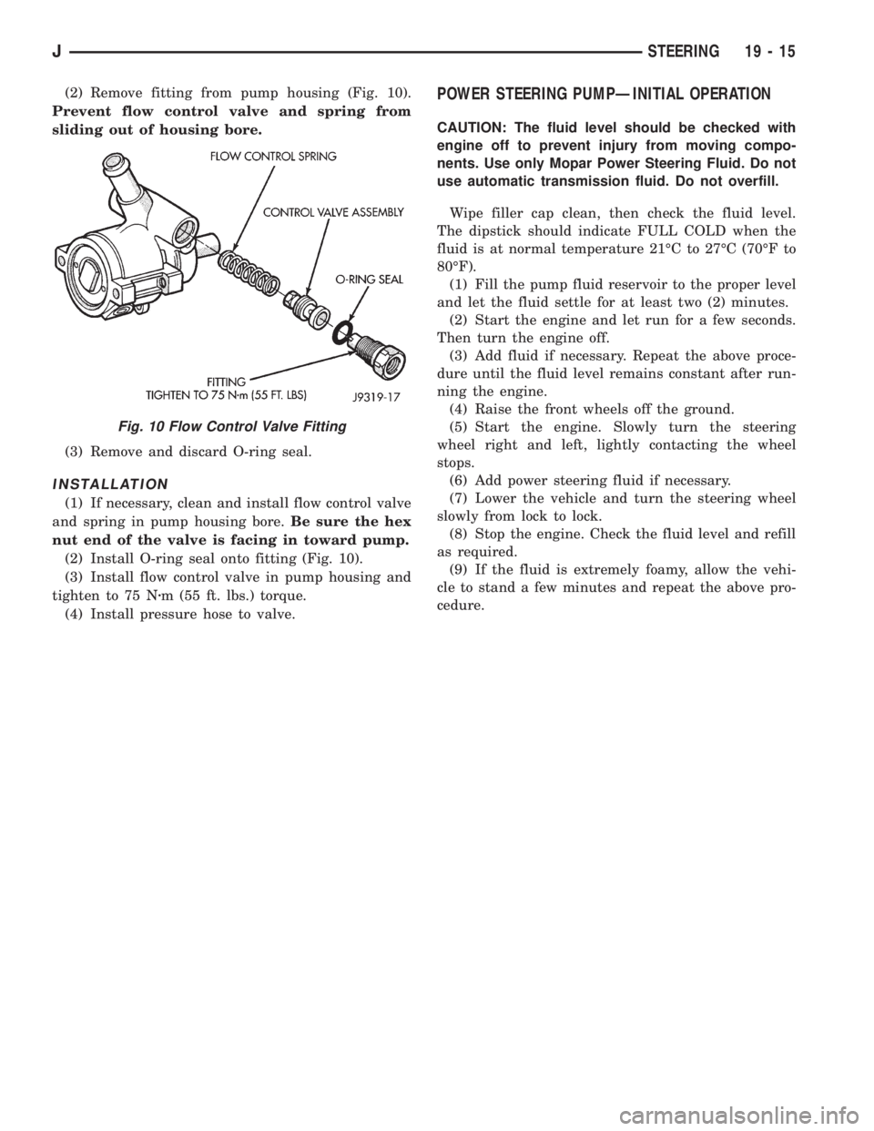
(2) Remove fitting from pump housing (Fig. 10).
Prevent flow control valve and spring from
sliding out of housing bore.
(3) Remove and discard O-ring seal.
INSTALLATION
(1) If necessary, clean and install flow control valve
and spring in pump housing bore.Be sure the hex
nut end of the valve is facing in toward pump.
(2) Install O-ring seal onto fitting (Fig. 10).
(3) Install flow control valve in pump housing and
tighten to 75 Nzm (55 ft. lbs.) torque.
(4) Install pressure hose to valve.
POWER STEERING PUMPÐINITIAL OPERATION
CAUTION: The fluid level should be checked with
engine off to prevent injury from moving compo-
nents. Use only Mopar Power Steering Fluid. Do not
use automatic transmission fluid. Do not overfill.
Wipe filler cap clean, then check the fluid level.
The dipstick should indicate FULL COLD when the
fluid is at normal temperature 21ÉC to 27ÉC (70ÉF to
80ÉF).
(1) Fill the pump fluid reservoir to the proper level
and let the fluid settle for at least two (2) minutes.
(2) Start the engine and let run for a few seconds.
Then turn the engine off.
(3) Add fluid if necessary. Repeat the above proce-
dure until the fluid level remains constant after run-
ning the engine.
(4) Raise the front wheels off the ground.
(5) Start the engine. Slowly turn the steering
wheel right and left, lightly contacting the wheel
stops.
(6) Add power steering fluid if necessary.
(7) Lower the vehicle and turn the steering wheel
slowly from lock to lock.
(8) Stop the engine. Check the fluid level and refill
as required.
(9) If the fluid is extremely foamy, allow the vehi-
cle to stand a few minutes and repeat the above pro-
cedure.
Fig. 10 Flow Control Valve Fitting
JSTEERING 19 - 15
Page 1636 of 2158
CONVERTER STALL TEST
Stall testing involves determining maximum engine
rpm obtainable at full throttle with the rear wheels
locked and the transmission in D range. This test
checks the holding ability of the converter overrun-
ning clutch and both of the transmission clutches.
When stall testing is completed, refer to the Stall
Speed Specifications chart and Stall Speed Diagnosis
guides.
WARNING: NEVER ALLOW ANYONE TO STAND IN
FRONT OF THE VEHICLE DURING A STALL TEST.
ALWAYS BLOCK THE FRONT WHEELS AND APPLY
THE SERVICE AND PARKING BRAKES DURING
THE TEST.
STALL TEST PROCEDURE
(1) Connect tachometer to engine.
(2) Check and adjust transmission fluid level.
(3) Start and run engine until transmission fluid
reaches normal operating temperature.
(4) Block front wheels.
(5) Fully apply service and parking brakes.
(6) Open throttle completely and record maximum
engine rpm registered on tachometer. It will take
from 3 to 10 seconds to reach maximum rpm. How-
ever, once maximum rpm has been achieved,do not
hold wide open throttle for more than 5 sec-
onds.
CAUTION: Stalling the converter causes a rapid in-
crease in fluid temperature. To avoid fluid overheat-
ing, hold wide open throttle for no more than 5
seconds after reaching peak rpm. In addition, if
more than one stall test is required, run the engine
at 1000 rpm with the transmission in Neutral for at
least 20 seconds to cool the fluid.
(7) Stall speeds should be in 1700-2150 rpm range.
CAUTION: If engine exceeds 2150 rpm, release ac-
celerator pedal immediately as transmission clutch
slippage is occurring.
(8) Shift transmission into Neutral. Run engine for
20-30 seconds at 1000 rpm to cool fluid. Then stop
engine, shift transmission into Park and release
brakes.
(9) Refer to Stall Test Diagnosis.
STALL TEST DIAGNOSIS
Stall Speed Too Low
Low stall speeds with a properly tuned engine in-
dicate a torque converter overrunning clutch prob-
lem. The condition should be confirmed by road
testing prior to converter replacement.The converter overrunning clutch is slipping when
stall speeds are 250 to 350 rpm below specified min-
imum.
A converter overrunning clutch failure will result
in sluggish acceleration in all speed ranges. It will
also require greater than normal throttle opening to
maintain cruising speeds.
Stall Speed Too High
If stall speed exceeds 2150 rpm, transmission
clutch slippage is occurring.
Stall Speed Normal But Acceleration Is Sluggish
If stall speeds are within specified range but abnor-
mal throttle opening is required for acceleration, or
to maintain cruise speeds, the converter overrunning
clutch is seized. The torque converter will have to be
replaced.
Converter Noise During Test
A whining noise caused by fluid flow is normal dur-
ing a stall test. However, loud metallic noises indi-
cate a damaged converter. To confirm that noise is
originating from the converter, operate the vehicle at
light throttle in Drive and Neutral on a hoist and lis-
ten for noise from the converter housing.
AIR PRESSURE TEST
Air pressure testing can be used to check clutch
and band operation with the transmission either in
the vehicle, or on the work bench as a final check af-
ter overhaul.
Air pressure testing requires that the oil pan and
valve body be removed from the transmission.
The servo and clutch apply passages are shown in
Figure 8.
Air Test Procedure
(1) Place one or two fingers on the clutch housing
and apply air pressure through front clutch apply
passage (Fig. 8). Piston movement can be felt and a
soft thud heard as the clutch applies.
(2) Place one or two fingers on the clutch housing
and apply air pressure through rear clutch apply
passage (Fig. 8). Piston movement can be felt and a
soft thud heard as the clutch applies.
(3) Apply air pressure to the front servo apply pas-
sage. The servo rod should extend and cause the
band to tighten around the drum. Spring tension
should release the servo when air pressure is re-
moved.
(4) Apply air pressure to the rear servo apply pas-
sage. The servo rod should extend and cause the
band to tighten around the drum. Spring tension
should release the servo when air pressure is re-
moved.
21 - 74 30RH/32RH TRANSMISSION DIAGNOSISJ
Page 1675 of 2158
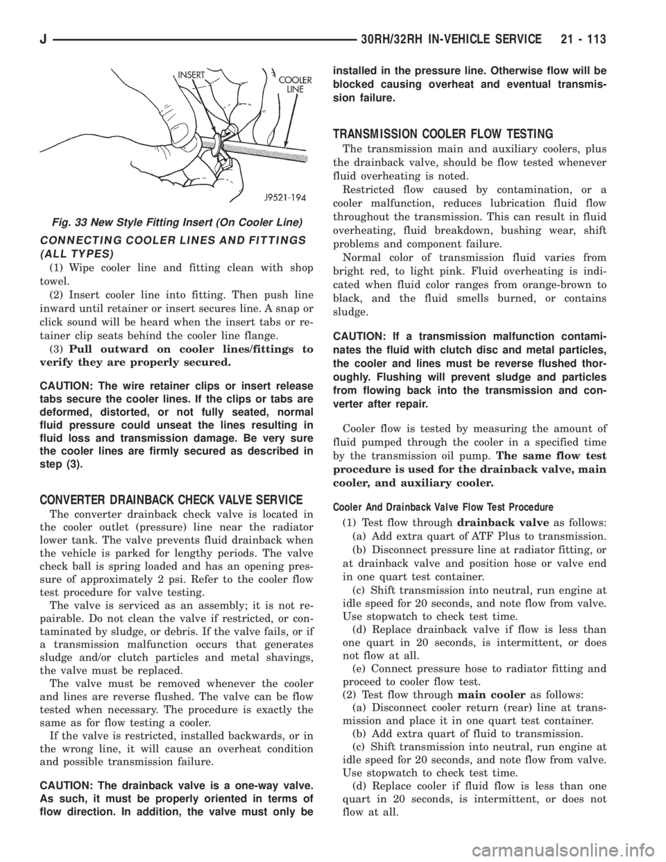
CONNECTING COOLER LINES AND FITTINGS
(ALL TYPES)
(1) Wipe cooler line and fitting clean with shop
towel.
(2) Insert cooler line into fitting. Then push line
inward until retainer or insert secures line. A snap or
click sound will be heard when the insert tabs or re-
tainer clip seats behind the cooler line flange.
(3)Pull outward on cooler lines/fittings to
verify they are properly secured.
CAUTION: The wire retainer clips or insert release
tabs secure the cooler lines. If the clips or tabs are
deformed, distorted, or not fully seated, normal
fluid pressure could unseat the lines resulting in
fluid loss and transmission damage. Be very sure
the cooler lines are firmly secured as described in
step (3).
CONVERTER DRAINBACK CHECK VALVE SERVICE
The converter drainback check valve is located in
the cooler outlet (pressure) line near the radiator
lower tank. The valve prevents fluid drainback when
the vehicle is parked for lengthy periods. The valve
check ball is spring loaded and has an opening pres-
sure of approximately 2 psi. Refer to the cooler flow
test procedure for valve testing.
The valve is serviced as an assembly; it is not re-
pairable. Do not clean the valve if restricted, or con-
taminated by sludge, or debris. If the valve fails, or if
a transmission malfunction occurs that generates
sludge and/or clutch particles and metal shavings,
the valve must be replaced.
The valve must be removed whenever the cooler
and lines are reverse flushed. The valve can be flow
tested when necessary. The procedure is exactly the
same as for flow testing a cooler.
If the valve is restricted, installed backwards, or in
the wrong line, it will cause an overheat condition
and possible transmission failure.
CAUTION: The drainback valve is a one-way valve.
As such, it must be properly oriented in terms of
flow direction. In addition, the valve must only beinstalled in the pressure line. Otherwise flow will be
blocked causing overheat and eventual transmis-
sion failure.
TRANSMISSION COOLER FLOW TESTING
The transmission main and auxiliary coolers, plus
the drainback valve, should be flow tested whenever
fluid overheating is noted.
Restricted flow caused by contamination, or a
cooler malfunction, reduces lubrication fluid flow
throughout the transmission. This can result in fluid
overheating, fluid breakdown, bushing wear, shift
problems and component failure.
Normal color of transmission fluid varies from
bright red, to light pink. Fluid overheating is indi-
cated when fluid color ranges from orange-brown to
black, and the fluid smells burned, or contains
sludge.
CAUTION: If a transmission malfunction contami-
nates the fluid with clutch disc and metal particles,
the cooler and lines must be reverse flushed thor-
oughly. Flushing will prevent sludge and particles
from flowing back into the transmission and con-
verter after repair.
Cooler flow is tested by measuring the amount of
fluid pumped through the cooler in a specified time
by the transmission oil pump.The same flow test
procedure is used for the drainback valve, main
cooler, and auxiliary cooler.
Cooler And Drainback Valve Flow Test Procedure
(1) Test flow throughdrainback valveas follows:
(a) Add extra quart of ATF Plus to transmission.
(b) Disconnect pressure line at radiator fitting, or
at drainback valve and position hose or valve end
in one quart test container.
(c) Shift transmission into neutral, run engine at
idle speed for 20 seconds, and note flow from valve.
Use stopwatch to check test time.
(d) Replace drainback valve if flow is less than
one quart in 20 seconds, is intermittent, or does
not flow at all.
(e) Connect pressure hose to radiator fitting and
proceed to cooler flow test.
(2) Test flow throughmain cooleras follows:
(a) Disconnect cooler return (rear) line at trans-
mission and place it in one quart test container.
(b) Add extra quart of fluid to transmission.
(c) Shift transmission into neutral, run engine at
idle speed for 20 seconds, and note flow from valve.
Use stopwatch to check test time.
(d) Replace cooler if fluid flow is less than one
quart in 20 seconds, is intermittent, or does not
flow at all.
Fig. 33 New Style Fitting Insert (On Cooler Line)
J30RH/32RH IN-VEHICLE SERVICE 21 - 113
Page 1719 of 2158
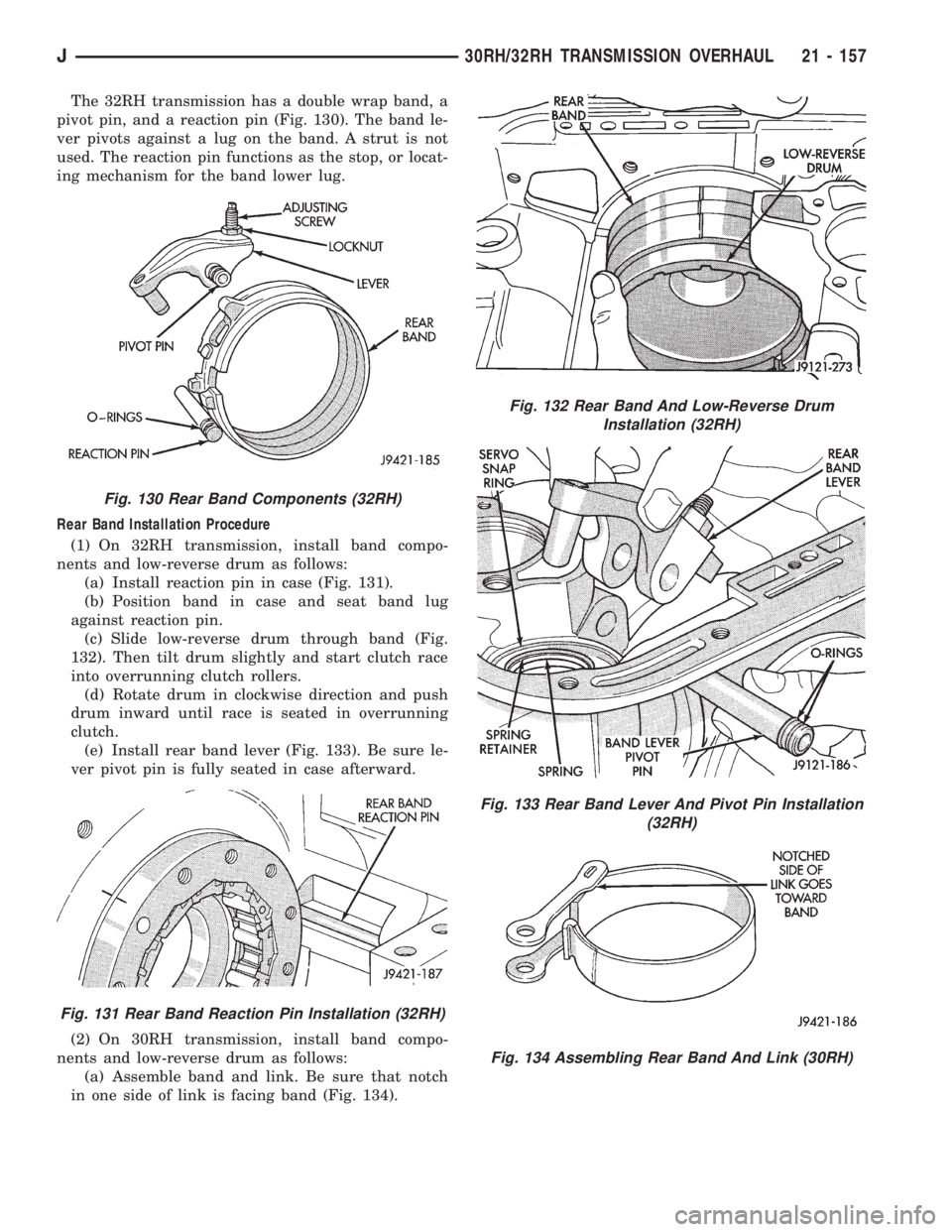
The 32RH transmission has a double wrap band, a
pivot pin, and a reaction pin (Fig. 130). The band le-
ver pivots against a lug on the band. A strut is not
used. The reaction pin functions as the stop, or locat-
ing mechanism for the band lower lug.
Rear Band Installation Procedure
(1) On 32RH transmission, install band compo-
nents and low-reverse drum as follows:
(a) Install reaction pin in case (Fig. 131).
(b) Position band in case and seat band lug
against reaction pin.
(c) Slide low-reverse drum through band (Fig.
132). Then tilt drum slightly and start clutch race
into overrunning clutch rollers.
(d) Rotate drum in clockwise direction and push
drum inward until race is seated in overrunning
clutch.
(e) Install rear band lever (Fig. 133). Be sure le-
ver pivot pin is fully seated in case afterward.
(2) On 30RH transmission, install band compo-
nents and low-reverse drum as follows:
(a) Assemble band and link. Be sure that notch
in one side of link is facing band (Fig. 134).
Fig. 130 Rear Band Components (32RH)
Fig. 131 Rear Band Reaction Pin Installation (32RH)
Fig. 132 Rear Band And Low-Reverse Drum
Installation (32RH)
Fig. 133 Rear Band Lever And Pivot Pin Installation
(32RH)
Fig. 134 Assembling Rear Band And Link (30RH)
J30RH/32RH TRANSMISSION OVERHAUL 21 - 157
Page 1943 of 2158
(3) Retain the tape stripe/decal firmly against flat
surface and separate the carrier from tape stripe/de-
cal.
(4) Use a sponge and apply solution to the tape
stripe/decal adhesive and to panel surface.
(5) Position the adhesive side of tape stripe/decal
on the panel with the bottom aligned with the char-
acter line.
²Align the end of the replacement tape stripe/decal
with the end of existing tape stripe/decal.
²Correctly align the index darts and index notches.
(6) If a complete replacement tape stripe/decal is
not being installed:
²Position the replacement tape stripe/decal section
at the center of the repair area.
²Align it with the existing tape stripe/decal.
²Allow at least 12 mm (1/2 in) of the tape stripe/de-
cal section to overlap the tape stripe/decal edges.
(7) Apply the wetting solution to the outer side of
the tape stripe/decal.
CAUTION: Avoid unnecessary pulling and stretch-
ing at the ends.
(8) Slide a squeegee from the center to the ends of
the tape stripe/decal. Use firm strokes to remove all
of the air bubbles.
(9) If a wrinkle is trapped in the tape stripe/decal
stop immediately. Lift the wrinkled area and re-align
it with the character line to remove the wrinkle.Do
not lift the tape stripe/decal if only a few air
bubbles exist.
(10) Where applicable, allow 12 mm (1/2 in) extra
tape stripe/decal to extend beyond edges.
(11) Fold the excess tape onto the inside flange and
adhere it with finger pressure.
(12) Inspect the tape stripe/decal installation with
the reflected light to find any damage.
(13) Remove all the air and moisture bubbles from
the tape stripe/decal with a needle or pin.
(14) Install any removed components and clean the
vehicle as necessary.
QUARTER WINDOW APPLIQUEÐXJ
REMOVAL/INSTALLATION
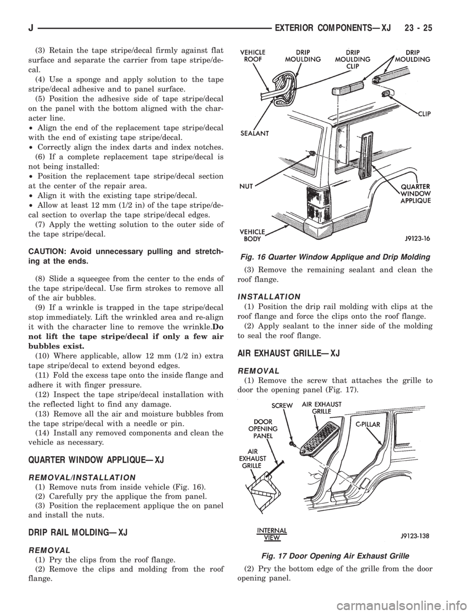
(1) Remove nuts from inside vehicle (Fig. 16).
(2) Carefully pry the applique the from panel.
(3) Position the replacement applique the on panel
and install the nuts.
DRIP RAIL MOLDINGÐXJ
REMOVAL
(1) Pry the clips from the roof flange.
(2) Remove the clips and molding from the roof
flange.(3) Remove the remaining sealant and clean the
roof flange.
INSTALLATION
(1) Position the drip rail molding with clips at the
roof flange and force the clips onto the roof flange.
(2) Apply sealant to the inner side of the molding
to seal the roof flange.
AIR EXHAUST GRILLEÐXJ
REMOVAL
(1) Remove the screw that attaches the grille to
door the opening panel (Fig. 17).
(2) Pry the bottom edge of the grille from the door
opening panel.
Fig. 16 Quarter Window Applique and Drip Molding
Fig. 17 Door Opening Air Exhaust Grille
JEXTERIOR COMPONENTSÐXJ 23 - 25
Page 2038 of 2158
painted panel surface. The solution will permit ease
of tape stripe/decal movement when positioning it on
the panel.
(5) Position adhesive-coated side of tape stripe/de-
cal on the panel with the bottom aligned with char-
acter line. Where applicable:
²align the end of the replacement tape stripe/decal
with the end of the existing tape stripe/decal, and
correctly align the index darts and index notches.
(6) If a complete replacement tape stripe/decal is
not being installed:
²Position the replacement tape stripe/decal section
at the center of the repair area.
²Align it with the existing tape stripe/decal and al-
low at least 12 mm (1/2 in) of the tape stripe/decal
section to overlap the existing tape stripe/decal
edges.(7) Apply wetting solution to the outer side of the
tape stripe/decal to allow the squeegee to freely slide
while adhering the stripe/decal to the panel.
CAUTION: Avoid unnecessary pulling and stretch-
ing at the ends of the tape stripe/decal because this
could cause it to tear.
(8) Position and slide a squeegee from the center to
the ends of the tape stripe/decal. This will ensure
complete bonding of the tape stripe/decal to the
painted panel surface.
(9) If a wrinkle is trapped in the tape stripe/decal
during the squeegee operation, stop. Lift wrinkled
area and re-align stripe/decal with panel character
line.Do not lift the tape stripe/decal if only a
few air bubbles exist.
(10) Where applicable, allow 12 mm (1/2 in) extra
tape stripe/decal to extend beyond the edges to be
folded over.
(11) Fold the excess tape stripe/decal back onto in-
side flange area.Use care to avoid trapping air
under the tape stripe/decal.Where necessary, trim
excess tape stripe/decal.
(12) Inspect tape installation with reflected light to
detect any defects that could have developed during
the installation.
(13) Remove all air and moisture bubbles from the
tape stripe/decal with a needle or pin.
(14) Install any removed components and clean the
vehicle as necessary.
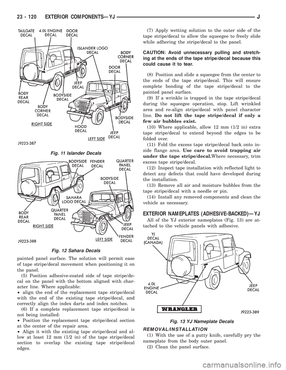
EXTERIOR NAMEPLATES (ADHESIVE-BACKED)ÐYJ
All of the YJ exterior nameplates (Fig. 13) are at-
tached to the vehicle panels with adhesive.
REMOVAL/INSTALLATION
(1) With the use of a putty knife, carefully pry the
nameplate from the body outer panel.
(2) Clean the panel surface.
Fig. 11 Islander Decals
Fig. 12 Sahara Decals
Fig. 13 YJ Nameplate Decals
23 - 120 EXTERIOR COMPONENTSÐYJJ
Page 2128 of 2158
BUMPERÐXJ, LIFTGATE LICENSE PLATE
SCREW ANCHOR.....................23-65
BUMPERÐXJ, REAR SEATBACK LATCH
STRIKER...........................23-84
BUMPERS......................13-16,13-5
BUS, CCD; FUEL/IGNITION (XJ).......8W-30-5
BUSHING AND PISTON CLEARANCE,
AW-4 .............................21-339
BUSHING REPLACEMENT, AXLE......2-12,2-34
BUSHING REPLACEMENT, LEAF SPRING
EYE; FRONT SUSPENSION AND AXLE.....2-17
BUSHING REPLACEMENT, LEAF SPRING
EYE; REAR SUSPENSION AND AXLES . . . 3-5,3-7
BUSHINGS, CLUTCH AND BRAKE PEDAL . . . 0-22
BUZZER, COMBINATION; INTERIOR
LIGHTING (YJ)....................8W-44-1
BUZZER MODULE.................8U-1,8U-2
BUZZER MODULE SCHEMATIC - YJ.......8U-4
CABLE, ACCELERATOR PEDAL AND
THROTTLE.....................14-17,14-58
CABLE ADJUSTMENT, PARK INTERLOCK . 21-195
CABLE ADJUSTMENT, SHIFT...........21-195
CABLE ADJUSTMENT, TRANSMISSION
THROTTLE.........................21-194
CABLE ADJUSTMENT, TRANSMISSION
THROTTLE VALVE....................21-71
CABLE ADJUSTMENT (XJ), PARK
INTERLOCK........................21-101
CABLE ADJUSTMENT (XJ), SHIFT.......21-100
CABLE ADJUSTMENT (XJ/YJ), THROTTLE
VALVE..............................21-101
CABLE REMOVE/INSTALL, SERVO.......8H-10
CABLE REPLACEMENT, TRANSMISSION
THROTTLE.........................21-193
CABLE REPLACEMENT (XJ), PARKING
BRAKE REAR.........................5-67
CABLE REPLACEMENT (YJ), PARKING
BRAKE FRONT........................5-67
CABLE REPLACEMENT (YJ), PARKING
BRAKE REAR.........................5-68
CABLE REPLACEMENTÐXJ, LATCH
RELEASE...........................23-11
CABLE RESISTANCE, SPARK PLUG......8D-14
CABLE, SERVO.......................8H-1
CABLE, SPEEDOMETER.................0-33
CABLE TENSIONER ADJUSTMENT
(XJ/YJ), PARKING BRAKE...............5-69
CABLE TENSIONER REPLACEMENT (XJ),
PARKING BRAKE......................5-66
CABLE, THROTTLE...................14-17
CABLE/LINKAGE ADJUSTMENT,
GEARSHIFT.........................21-71
CABLES, DISTRIBUTOR CAP AND
ROTOR, IGNITION.....................0-20
CABLES, SPARK PLUG SECONDARY.....8D-14,
8D-24
CABLES, VENT DOOR CONTROL.........24-32
CALIBRATION, COMPASS...............8C-5
CALIPER ASSEMBLY...................5-50
CALIPER CLEANING AND INSPECTION.....5-50
CALIPER DISASSEMBLY................5-48
CALIPER INSTALLATION................5-51
CALIPER OPERATION AND WEAR
COMPENSATION......................5-45
CALIPER REMOVAL....................5-48
CAMSHAFT......................9-32,9-74
CAMSHAFT PIN REPLACEMENT......9-34,9-75
CAMSHAFT POSITION SENSOR; FUEL
SYSTEM............................14-60
CAMSHAFT POSITION SENSOR;
FUEL/IGNITION (XJ)................8W-30-3
CAMSHAFT POSITION SENSOR;
FUEL/IGNITION (YJ)................8W-30-3
CAMSHAFT POSITION SENSOR;
IGNITION SYSTEMS..............8D-17,8D-2
CAMSHAFT POSITION SENSOR;
FUEL/IGNITION (XJ-RHD)............8W-30-3
CAMSHAFT POSITION SENSOR TEST;
FUEL SYSTEM.......................14-46
CAMSHAFT POSITION SENSOR TEST;
IGNITION SYSTEMS
...................8D-6
CAMSHAFT POSITION SENSORÐPCM
INPUT
.............................14-22
(CANADA ONLY)ÐXJ, DAYTIME
RUNNING LIGHTS
....................8L-15
(CANADA ONLY)ÐYJ, DAYTIME
RUNNING LIGHTS
....................8L-30
CANISTER, EVAP
..................25-4,25-7CAP AND ROTOR, IGNITION CABLES,
DISTRIBUTOR........................0-20
CAP, DISTRIBUTOR....................8D-7
CAP, FUEL TANK FILLER TUBE;
EMISSION CONTROL SYSTEMS......25-4,25-7
CAP, FUEL TANK FILLER TUBE; FUEL
SYSTEM............................14-13
CAP, RADIATOR PRESSURE.............7-25
CAPACITIES, COOLING SYSTEM..........7-45
CAPACITIES, FLUID.....................0-3
CAPACITIES, FUEL TANK..........14-13,14-67
CAPACITY TEST, FUEL PUMP............14-7
CAR REPLACEMENT, PITMAN SHAFT
SEALSÐIN.........................19-23
CARDAN (CV), DOUBLE................16-11
CARDAN, SINGLE....................16-10
CARGO BARRIERÐXJ................23-101
CARGO LAMP AND DOME LAMP;
INTERIOR LIGHTING (XJ-RHD)........8W-44-1
CARGO LAMP, COURTESY LAMPS AND
DOME LAMP; INTERIOR LIGHTING (XJ) . 8W-44-1
CARGO LAMPÐXJ...................23-94
CARPET/MATÐXJ, FRONT.............23-99
CARPET/MATÐXJ, REAR.............23-100
CARPETÐYJ.......................23-156
CARPETS AND FLOOR MATSÐXJ.......23-99
CARRIERÐYJ, EXTERNAL SPARE/
WHEEL TIRE.......................23-133
CASE (4WD VEHICLES), TRANSFER........0-24
CASE ASSEMBLY, TRANSFER....21-294,21-319
CASE CHANGES, TRANSFER...........21-307
CASE CLEANING AND INSPECTION,
TRANSMISSION.....................21-125
CASE COVER OIL SEAL REPLACEMENT,
TIMING.........................9-30,9-73
CASE COVER, TIMING..............9-31,9-72
CASE DISASSEMBLY AND OVERHAUL,
TRANSFER...................21-289,21-310
CASE IDENTIFICATION, TRANSFER.....21-284,
21-307
CASE INSTALLATION, TRANSFER . 21-288,21-309
CASE LUBRICANT AND FILL LEVEL,
TRANSFER.........................21-284
CASE, NP231 TRANSFER.......21-283,21-305
CASE, NP242 TRANSFER.......21-307,21-331
CASE OVERHAUL, FIRST-REVERSE
BRAKE PISTON AND TRANSMISSION....21-247
CASE REMOVAL, TRANSFER.....21-287,21-309
CASE SKID PLATE, TRANSFER......13-15,13-3
CASE SPECIFICATIONS, TRANSMISSION/
TRANSFER.........................21-333
CATALYTIC CONVERTER............11-1,11-4
CATALYTIC CONVERTOR................25-1
CAUTIONS, AND WARNINGS, NOTES;
WIRING DIAGRAMSÐGENERAL
INFORMATION (XJ)...................8W-1
CCD BUS; FUEL/IGNITION (XJ)........8W-30-5
CENTER HIGH MOUNTED STOP LAMP
(CHMSL)ÐXJ.......................8L-12
CENTER HIGH MOUNTED STOP LAMP
(CHMSL)ÐYJ.......................8L-28
CERTIFICATION LABEL, VEHICLE SAFETY . Intro.-4
CHAIN AND SPROCKETS, TIMING....9-31,9-73
CHANGE AND FILTER REPLACEMENT,
ENGINE OIL
..........................0-16
CHANGE, LUBRICANT; FRONT
SUSPENSION AND AXLE
................2-23
CHANGE, LUBRICANT; REAR
SUSPENSION AND AXLES
...........3-13,3-31
CHANGE, REFILLING AFTER OVERHAUL
OR FLUID/FILTER
..............21-100,21-182
CHANGES AND PARTS
INTERCHANGEABILITY, TRANSMISSION
. . . 21-67
CHANGES, TRANSFER CASE
...........21-307
CHANNEL REPLACEMENTÐYJ, DOOR
FRAME GLASS
......................23-142
CHARGING, BATTERY
..................8A-7
CHARGING REFRIGERANT SYSTEM
......24-11
CHARGING SYSTEM; BATTERY/
STARTING/CHARGING SYSTEMS
DIAGNOSTICS
.......................8A-17
CHARGING SYSTEM; CHARGING
SYSTEM (XJ)
.....................8W-20-1
CHARGING SYSTEM; CHARGING
SYSTEM (XJ-RHD)
.................8W-20-1
CHARGING SYSTEM; CHARGING
SYSTEM (YJ)
.....................8W-20-1CHARGING SYSTEM INDICATOR LAMP;
INSTRUMENT CLUSTER (XJ).........8W-40-3
CHARGING SYSTEM SPECIFICATIONS....8A-23
CHARGING TIME TABLE, BATTERY........8A-8
CHART, MAIN BEARING FITTING......9-48,9-90
CHART, XJ PERFORMANCE
TEMPERATURE AND PRESSURE.........24-13
CHART, YJ PERFORMANCE
TEMPERATURE AND PRESSURE.........24-13
CHARTÐAX 15 MANUAL
TRANSMISSION, SELECTIVE SNAP
RING.............................21-334
CHARTS, BRAKELINE..................5-12
CHARTS, DIAGNOSIS GUIDES...........21-77
CHARTS, GEARTRAIN OPERATION AND
APPLICATION.......................21-169
CHARTS, INSPECTION AND DIAGNOSIS.....6-4
CHASSIS AND BODY COMPONENTS.......0-28
CHASSIS COMPONENT AND WHEEL
BEARING LUBRICANTS.................0-28
CHECK VALVE TEST, POWER BOOSTER.....5-9
CHECKING FLUID LEVEL AND
CONDITION........................21-182
CHECKS, PRELIMINARY.................7-5
CHIME/BUZZER MODULE; INTERIOR
LIGHTING (XJ)....................8W-44-2
CHIME/BUZZER MODULE; INTERIOR
LIGHTING (XJ-RHD)................8W-44-2
CHMSL LAMPS, STOP LAMPS; REAR
LIGHTING (XJ)....................8W-51-1
CHMSL LAMPS, STOP LAMPS; REAR
LIGHTING (XJ-RHD)................8W-51-1
CHMSL LAMPS, STOP LAMPS; REAR
LIGHTING (YJ)....................8W-51-1
(CHMSL)ÐXJ, CENTER HIGH MOUNTED
STOP LAMP.........................8L-12
(CHMSL)ÐYJ, CENTER HIGH MOUNTED
STOP LAMP.........................8L-28
CIGAR LIGHTER; HORN/CIGAR LIGHTER . . . 8E-1
CIGAR LIGHTER; HORN/CIGAR LIGHTER
(YJ).............................8W-41-1
CIGAR LIGHTER; INSTRUMENT CLUSTER
(XJ).............................8W-40-1
CIRCUIT IDENTIFICATION; WIRING
DIAGRAMSÐGENERAL INFORMATION
(XJ)...............................8W-1
CIRCUIT REMOVE/INSTALL, PRINTED....8E-19,
8E-40
CIRCUIT SENSEÐPCM INPUT, IGNITION . . 14-23
CIRCUIT VOLTAGE, OPEN...............8A-6
CLAMPS, FUEL TUBES/LINES/HOSES . 14-62,14-9
CLASSIFICATION OF LUBRICANTS.........0-2
CLASSIFICATIONS AND RATINGS,
BATTERY...........................8A-23
CLEANER, AIR.......................14-29
CLEANER ELEMENT, AIR; EMISSION
CONTROL SYSTEMS...................25-7
CLEANER ELEMENT, AIR; FUEL SYSTEM . . 14-59
CLEANER ELEMENT, AIR; LUBRICATION
AND MAINTENANCE...................0-18
CLEANER HOUSING, AIR...............14-58
CLEANING AND INSPECTION, CALIPER....5-50
CLEANING AND INSPECTION, GEAR......19-42
CLEANING AND INSPECTION,
TRANSMISSION CASE................21-125
CLEANING OF TIRES...................22-2
CLEANING/INSPECTION; FRONT
SUSPENSION AND AXLE
................2-37
CLEANING/INSPECTION; REAR
SUSPENSION AND AXLES
...............3-20
CLEANING/REVERSE FLUSHING,
COOLING SYSTEM
....................7-22
CLEARANCE AND RAMP ANGLE,
GROUND
............................0-11
CLEARANCE, AW-4 BUSHING AND
PISTON
...........................21-339
CLOCKSPRING
.......................19-51
CLUSTER AND GAUGE HOUSINGSÐYJ,
INSTRUMENT
......................23-151
CLUSTER ASSEMBLY REMOVE/INSTALL
. . 8E-17,
8E-35
CLUSTER BEZELÐXJ, INSTRUMENT
.....23-80
CLUSTER BEZELÐYJ, INSTRUMENT
....23-151
CLUSTER CONNECTORS (RHD)
.........8E-11
CLUSTER, GAUGE PACKAGE
.......8E-31,8E-43
CLUSTER GROUND; INSTRUMENT
CLUSTER (XJ)
.....................8W-40-3
4 INDEXJ
Description Group-Page Description Group-Page Description Group-Page
Page 2137 of 2158
HEATER AND A/C CONTROL
REPLACEMENT......................24-23
HEATER AND A/C OPERATION...........24-1
HEATER AND AIR CONDITIONING; AIR
CONDITIONING/HEATER (YJ).........8W-42-2
HEATER CONTROL PANEL LAMP,
ACCESSORY LAMP; INTERIOR
LIGHTING (YJ)....................8W-44-1
HEATER CONTROL REPLACEMENT.......24-32
HEATER CORE.......................24-26
HEATER CORE AND HOUSING..........24-33
HEATER DIAGNOSIS..................24-17
HEATER ELEMENTS; POWER MIRRORS
(XJ-RHD).........................8W-62-1
HEATER, ENGINE BLOCK................7-44
HEATER HOUSING REPLACEMENT.......24-26
HEATER SYSTEM; AIR CONDITIONING/
HEATER (XJ)......................8W-42-1
HEATER SYSTEM; AIR CONDITIONING/
HEATER (XJ-RHD)..................8W-42-1
HEATER SYSTEM; AIR CONDITIONING/
HEATER (YJ)......................8W-42-1
HEATER/DEFROSTER/INSTRUMENT
PANEL OUTLET VACUUM MOTOR
REPLACEMENT......................24-26
HEATING AND AIR CONDITIONING TEST
PROCEDURES.......................24-15
HEATING ELEMENT TEST, OXYGEN
SENSOR (O2S)......................14-48
HEATING SCHEMATICÐXJ..............24-2
HEATING SYSTEM DIAGNOSIS..........24-18
HELPFUL INFORMATION; CHARGING
SYSTEM (XJ).....................8W-20-1
HELPFUL INFORMATION; CHARGING
SYSTEM (XJ-RHD).................8W-20-1
HELPFUL INFORMATION; CHARGING
SYSTEM (YJ).....................8W-20-1
HELPFUL INFORMATION; POWER SEAT
(XJ).............................8W-63-1
HELPFUL INFORMATION; POWER
WINDOWS (XJ)....................8W-60-2
HELPFUL INFORMATION; POWER
WINDOWS (XJ-RHD)...............8W-60-2
HELPFUL INFORMATION; TRAILER TOW
(XJ).............................8W-54-1
HELPFUL INFORMATION; TRAILER TOW
(XJ-RHD).........................8W-54-1
HIGH MOUNTED STOP LAMP
(CHMSL)ÐXJ, CENTER................8L-12
HIGH MOUNTED STOP LAMP
(CHMSL)ÐYJ, CENTER................8L-28
HIGH PEDAL EFFORT, HARD PEDAL OR.....5-6
HIGH-BEAM INDICATOR LAMP;
INSTRUMENT CLUSTER (XJ).........8W-40-2
HIGH-BEAM INDICATOR LAMP;
INSTRUMENT CLUSTER (XJ-RHD).....8W-40-2
HIGH-LINE GAUGE CLUSTER (LHD).......8E-9
HIGH-PRESSURE CUT-OFF SWITCH,
LOW-PRESSURE................24-15,24-16
HINGE REPLACEMENTÐXJ, HOOD.......23-10
HINGE/HINGE PIN REPLACEMENTÐXJ,
DOOR.............................23-52
HINGEÐXJ, LIFTGATE.................23-60
HINGEÐYJ, TAILGATE................23-121
HINGESÐYJ, FULL-METAL DOOR.......23-140
HITCH, TRAILER.....................23-77
HITCHÐXJ, TRAILER.................23-77
HOISTING, JUMP STARTING, TOWING......0-9
HOISTING RECOMMENDATIONS..........0-10
HOLD AFTER DRIVING THROUGH DEEP
WATER PUDDLES, BRAKES DO NOT.......5-7
HOLDDOWN AND FLOOR BRACKETSÐ
XJ, SPARE TIRE/WHEEL...............23-98
HONING CYLINDER BORES...............9-2
HOOD ADJUSTMENTÐXJ..............23-10
HOOD ALIGNMENTÐYJ..............23-107
HOOD HINGE REPLACEMENTÐXJ.......23-10
HOOD INSULATOR PANELÐYJ.........23-107
HOOD LATCH REPLACEMENTÐXJ.......23-11
HOOD LATCH STRIKER REPLACEMENTÐ
XJ ................................23-11
HOOD SAFETY LATCHÐYJ............23-109
HOODÐXJ...........................23-7
HOODÐYJ
.........................23-107
HOOK, REAR TOW
.....................13-9
HOOKS, FRONT TOW
..................13-7
HOOKS, TOW
........................13-13
HORN; HORN/CIGAR LIGHTER
...........8E-1HORN; HORN/CIGAR LIGHTER (YJ)....8W-41-1
HORN; INSTRUMENT CLUSTER (XJ) . . . 8W-40-1
HORN CONTACT/CLOCKSPRING..........8G-4
HORN RELAY........................8G-1
HORN REMOVE/INSTALL...............8G-3
HORN SWITCH.......................8G-1
HORN SWITCH REMOVE/INSTALL........8G-3
HORNS.............................8G-1
HOSE REPLACEMENT, PRESSURE AND
RETURN............................19-11
HOSE ROUTING SCHEMATICS, VACUUM . . . 25-2
HOSE SPLASH SHIELDÐXJ VEHICLES,
FUEL FILLER.........................13-4
HOSES, BRAKE FLUIDÐBRAKE
BLEEDINGÐBRAKELINES...............5-10
HOSES, BRAKELINES..................5-12
HOSES, COOLING SYSTEM..............7-32
HOSES/TUBES PRECAUTIONS,
REFRIGERANT.......................24-10
HOSES/TUBING, RUBBER AND PLASTIC....0-26
HOUSING, AIR CLEANER...............14-58
HOUSING COMPONENTSÐYJ,
EVAPORATIVE........................24-6
HOUSING END PLUG..................19-28
HOUSING, EVAPORATOR...............24-35
HOUSING, EVAPORATOR/BLOWER.......24-29
HOUSING, HEATER CORE..............24-33
HOUSING INSPECTION AND PARK LOCK
COMPONENT OVERHAUL, ADAPTER/
EXTENSION........................21-127
HOUSING LEAK DIAGNOSIS,
CONVERTER........................21-75
HOUSING MISALIGNMENT, CLUTCH........6-4
HOUSING REPLACEMENT, CLUTCH.......6-13
HOUSING REPLACEMENT, HEATER.......24-26
HOUSING SEAL REPLACEMENT,
ADAPTER..........................21-191
HOUSINGÐXJ, LIFTGATE LICENSE
PLATE LAMP........................23-65
HOUSINGSÐYJ, INSTRUMENT CLUSTER
AND GAUGE........................23-151
HOW TO USE THIS GROUP; WIRING
DIAGRAMS (XJ)......................8W-1
HOW TO USE THIS GROUP; WIRING
DIAGRAMS (XJ-RHD)..................8W-1
HOW TO USE THIS GROUP; WIRING
DIAGRAMS (YJ)......................8W-1
HUB BEARING AND AXLE SHAFT.........2-25
HYDRAULIC CONTROL UNIT; ANTI-LOCK
BRAKES (XJ)......................8W-32-2
HYDRAULIC CONTROL UNIT; ANTI-LOCK
BRAKES (XJ-RHD).................8W-32-2
HYDRAULIC CONTROL UNIT; ANTI-LOCK
BRAKES (YJ)......................8W-32-2
HYDRAULIC CONTROL UNIT (HCU).......5-33
HYDRAULIC LINKAGE COMPONENTS.......6-1
HYDRAULIC LINKAGE INSTALLATION,
CLUTCH.............................6-14
HYDRAULIC LINKAGE REMOVAL,
CLUTCH.............................6-13
HYDRAULIC PRESSURE TEST.....21-177,21-72
HYDRAULIC SYSTEM................21-169
HYDRAULIC TAPPETS..............9-24,9-66
HYDROSTATIC LOCK
....................9-4
IDENTIFICATION, AW-4 ACCUMULATOR
COMPONENT
.......................21-342
IDENTIFICATION, AW-4 VALVE AND
SPRING
...........................21-343
IDENTIFICATION, BOLT
..............Intro.-14
IDENTIFICATION, CIRCUIT; WIRING
DIAGRAMSÐGENERAL INFORMATION
(XJ)
...............................8W-1
IDENTIFICATION, ENGINE AND
TRANSMISSION/TRANSFER CASE
......Intro.-5
IDENTIFICATION, MAJOR COMPONENT
. . Intro.-5
IDENTIFICATION NUMBER (VIN)
DECODING, VEHICLE
................Intro.-4
IDENTIFICATION NUMBER (VIN) PLATE,
VEHICLE
..........................Intro.-4
IDENTIFICATION, SECTION; WIRING
DIAGRAMS (XJ)
......................8W-1
IDENTIFICATION, SECTION; WIRING
DIAGRAMS (XJ-RHD)
..................8W-1
IDENTIFICATION, SECTION; WIRING
DIAGRAMS (YJ)
......................8W-1
IDENTIFICATION, TRANSFER CASE
.....21-284,
21-307IDENTIFICATION, TRANSMISSION . 21-166,21-33,
21-67,21-2
IDENTIFICATION, WIRE CODE; WIRING
DIAGRAMSÐGENERAL INFORMATION
(XJ)...............................8W-1
IDENTIFICATION/SYSTEM OPERATION,
COMPONENT.........................8D-1
IDLE AIR CONTROL (IAC) MOTOR; FUEL
SYSTEM............................14-62
IDLE AIR CONTROL (IAC) MOTOR;
FUEL/IGNITION (XJ)................8W-30-2
IDLE AIR CONTROL (IAC) MOTOR;
FUEL/IGNITION (YJ)................8W-30-2
IDLE AIR CONTROL (IAC) MOTOR;
FUEL/IGNITION (XJ-RHD)............8W-30-2
IDLE AIR CONTROL (IAC) MOTORÐPCM
OUTPUT............................14-27
IDLE AIR CONTROL MOTOR TEST.......14-49
IDLE SWITCH, EXTENDED...........8W-30-5
IDLE SWITCH TEST, EXTENDED.........14-48
IDLE SWITCHÐPCM INPUT, EXTENDED . . . 14-23
IGNITION CABLES, DISTRIBUTOR CAP
AND ROTOR.........................0-20
IGNITION CIRCUIT SENSEÐPCM INPUT . . 14-23
IGNITION COIL; FUEL SYSTEM..........14-62
IGNITION COIL; FUEL/IGNITION (XJ) . . . 8W-30-2
IGNITION COIL; FUEL/IGNITION (YJ) . . . 8W-30-2
IGNITION COIL; IGNITION SYSTEMS.....8D-22,
8D-4,8D-9
IGNITION COIL; FUEL/IGNITION
(XJ-RHD).........................8W-30-2
IGNITION COIL RESISTANCE............8D-9
IGNITION COILÐPCM OUTPUT..........14-28
IGNITION FEED; FUEL/IGNITION
(XJ-RHD).........................8W-30-1
IGNITION KEY-IN SWITCH..........8U-1,8U-2
IGNITION SECONDARY CIRCUIT
DIAGNOSIS.........................8D-10
IGNITION SWITCH; BRAKES.............5-35
IGNITION SWITCH; FUEL/IGNITION (XJ) . 8W-30-1
IGNITION SWITCH; FUEL/IGNITION (YJ) . 8W-30-1
IGNITION SWITCH; FUEL/IGNITION
(XJ-RHD).........................8W-30-1
IGNITION SWITCH AND KEY CYLINDER
SERVICE...........................8D-26
IGNITION SWITCH CONTINUITY TESTS . . . 8D-30
IGNITION SWITCH LAMP; INTERIOR
LIGHTING (XJ)....................8W-44-1
IGNITION SWITCH LAMP; INTERIOR
LIGHTING (XJ-RHD)................8W-44-1
IGNITION SWITCH SERVICE............19-54
IGNITION SWITCHÐXJ MODELS........8D-26
IGNITION SWITCHÐYJ MODELS........8D-29
IGNITION TIMING....................8D-11
ILLUMINATION LAMPS, CLUSTER . . 8E-16,8E-26,
8E-34,8E-4
ILLUMINATION LAMPS, INSTRUMENT
PANEL; INTERIOR LIGHTING (XJ).....8W-44-1
ILLUMINATION LAMPS, INSTRUMENT
PANEL; INTERIOR LIGHTING (XJ-RHD) . 8W-44-1
ILLUMINATION, RADIO; RADIO (XJ)....8W-47-1
ILLUMINATION, RADIO; RADIO
(XJ-RHD).........................8W-47-1
ILLUMINATION, RADIO; RADIO (YJ)....8W-47-1
ILLUMINATION RELAY CONNECTIONS,
RADIO
..............................8F-4
ILLUMINATION RELAY, RADIO
........8F-1,8F-4
IMPACT SENSOR/INFLATOR ASSEMBLY
. . . 8M-2
INCORRECT FLUID LEVEL, EFFECTS OF
. . . 21-71
INDEX, DIAGRAM; AIR CONDITIONING/
HEATER (XJ)
......................8W-42-2
INDEX, DIAGRAM; AIR CONDITIONING/
HEATER (XJ-RHD)
..................8W-42-2
INDEX, DIAGRAM; AIR CONDITIONING/
HEATER (YJ)
...............8W-42-1,8W-42-2
INDEX, DIAGRAM; ANTI-LOCK BRAKES
(XJ)
.............................8W-32-3
INDEX, DIAGRAM; ANTI-LOCK BRAKES
(XJ-RHD)
.........................8W-32-3
INDEX, DIAGRAM; ANTI-LOCK BRAKES
(YJ)
.............................8W-32-2
INDEX, DIAGRAM; CHARGING SYSTEM
(XJ)
.............................8W-20-1
INDEX, DIAGRAM; CHARGING SYSTEM
(XJ-RHD)
.........................8W-20-1
INDEX, DIAGRAM; CHARGING SYSTEM
(YJ)
.............................8W-20-1
JINDEX 13
Description Group-Page Description Group-Page Description Group-Page