1995 JEEP YJ radiator cap
[x] Cancel search: radiator capPage 1382 of 2158
INSTALLATION
(1) Install the muffler onto the catalytic converter
outlet. Ensure that the locator on the converter
aligns with the notch on the muffler, if so equipped.
Install the clamp and tighten the nuts finger tight.
(2) Install the exhaust tailpipe into the muffler
outlet. Ensure that the locator on the exhaust
tailpipe aligns with the notch on the muffler, if so
equipped. Install the clamp and tighten the nuts fin-
ger tight.
(3) Install the front exhaust tailpipe supports and
the rear exhaust tailpipe hanger. Ensure that the ex-
haust tailpipe has sufficient clearance from the floor
pan and shields.
(4) Tighten the nuts on the muffler-to-catalytic
converter and the muffler-to-exhaust tailpipe clamps
to 61 Nzm (45 ft. lbs.) torque.
(5) Lower the vehicle.
(6) Start the engine and inspect for exhaust leaks
and contact with the body panels and shields.
ENGINE EXHAUST MANIFOLDÐ2.5L ENGINE
REMOVAL
(1) Disconnect the battery negative cable.
(2) Remove all components attached to the intake
manifold.
(3) Raise the vehicle.
(4) Disconnect the exhaust pipe from the engine
exhaust manifold.
(5) Lower the vehicle.
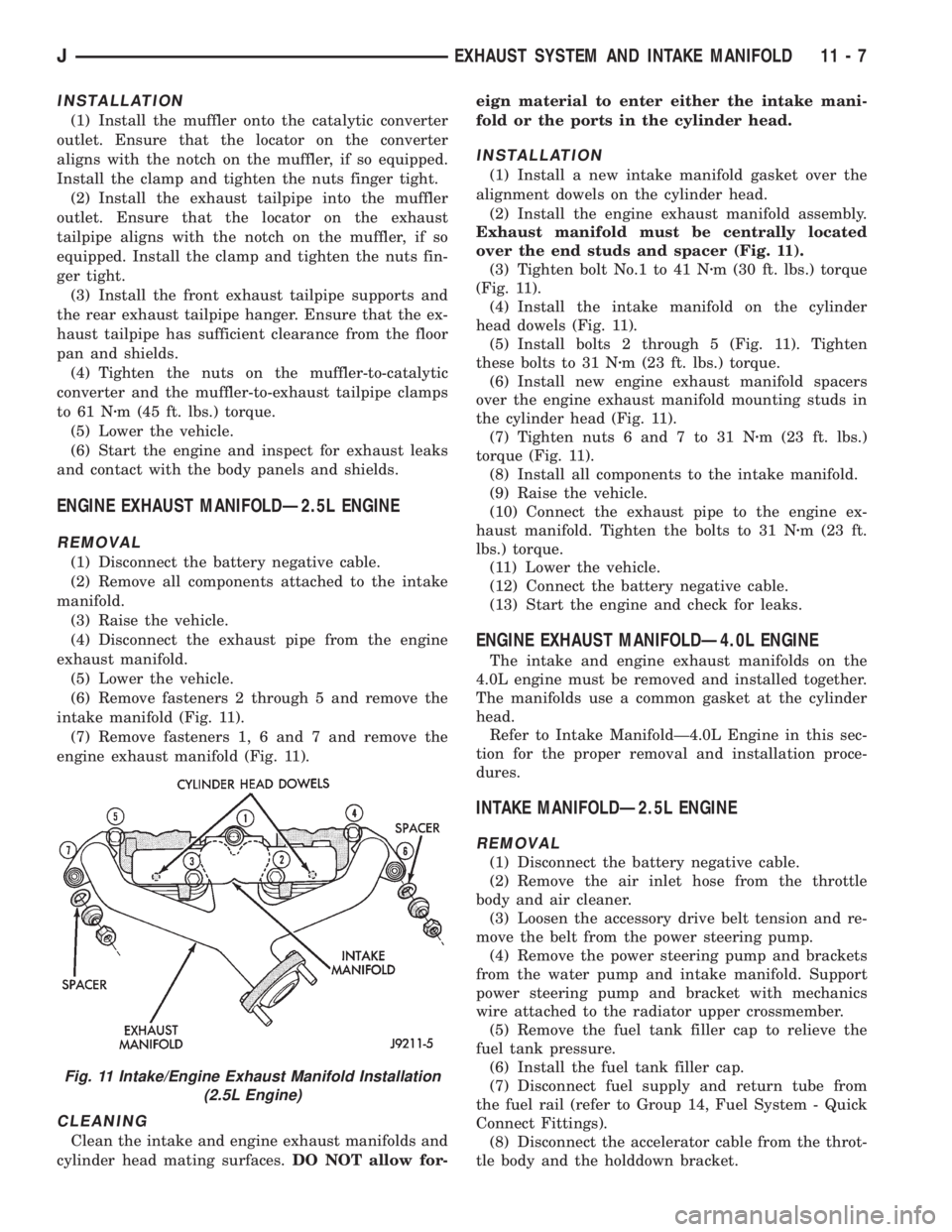
(6) Remove fasteners 2 through 5 and remove the
intake manifold (Fig. 11).
(7) Remove fasteners 1, 6 and 7 and remove the
engine exhaust manifold (Fig. 11).
CLEANING
Clean the intake and engine exhaust manifolds and
cylinder head mating surfaces.DO NOT allow for-eign material to enter either the intake mani-
fold or the ports in the cylinder head.
INSTALLATION
(1) Install a new intake manifold gasket over the
alignment dowels on the cylinder head.
(2) Install the engine exhaust manifold assembly.
Exhaust manifold must be centrally located
over the end studs and spacer (Fig. 11).
(3) Tighten bolt No.1 to 41 Nzm (30 ft. lbs.) torque
(Fig. 11).
(4) Install the intake manifold on the cylinder
head dowels (Fig. 11).
(5) Install bolts 2 through 5 (Fig. 11). Tighten
these bolts to 31 Nzm (23 ft. lbs.) torque.
(6) Install new engine exhaust manifold spacers
over the engine exhaust manifold mounting studs in
the cylinder head (Fig. 11).
(7) Tighten nuts 6 and 7 to 31 Nzm (23 ft. lbs.)
torque (Fig. 11).
(8) Install all components to the intake manifold.
(9) Raise the vehicle.
(10) Connect the exhaust pipe to the engine ex-
haust manifold. Tighten the bolts to 31 Nzm (23 ft.
lbs.) torque.
(11) Lower the vehicle.
(12) Connect the battery negative cable.
(13) Start the engine and check for leaks.
ENGINE EXHAUST MANIFOLDÐ4.0L ENGINE
The intake and engine exhaust manifolds on the
4.0L engine must be removed and installed together.
The manifolds use a common gasket at the cylinder
head.
Refer to Intake ManifoldÐ4.0L Engine in this sec-
tion for the proper removal and installation proce-
dures.
INTAKE MANIFOLDÐ2.5L ENGINE
REMOVAL
(1) Disconnect the battery negative cable.
(2) Remove the air inlet hose from the throttle
body and air cleaner.
(3) Loosen the accessory drive belt tension and re-
move the belt from the power steering pump.
(4) Remove the power steering pump and brackets
from the water pump and intake manifold. Support
power steering pump and bracket with mechanics
wire attached to the radiator upper crossmember.
(5) Remove the fuel tank filler cap to relieve the
fuel tank pressure.
(6) Install the fuel tank filler cap.
(7) Disconnect fuel supply and return tube from
the fuel rail (refer to Group 14, Fuel System - Quick
Connect Fittings).
(8) Disconnect the accelerator cable from the throt-
tle body and the holddown bracket.
Fig. 11 Intake/Engine Exhaust Manifold Installation
(2.5L Engine)
JEXHAUST SYSTEM AND INTAKE MANIFOLD 11 - 7
Page 1437 of 2158
MULTI-PORT FUEL INJECTION (MFI)ÐGENERAL DIAGNOSIS
INDEX
page page
Automatic Shutdown (ASD) Relay Testing....... 46
Camshaft Position Sensor Test............... 46
Crankshaft Position Sensor Test.............. 47
Diagnostic Trouble Code (DTC)............... 54
DRB Scan Tool........................... 54
Engine Coolant Temperature Sensor Test....... 46
Extended Idle Switch Test................... 48
Fuel Injector Test......................... 51
Fuel Pump Relay Testing................... 47
Fuel System Pressure Test.................. 51
General Information....................... 35
Idle Air Control Motor Test................... 49
Intake Manifold Air Temperature Sensor Test..... 46Manifold Absolute Pressure (Map) Sensor Test . . . 47
On-Board Diagnostics (OBD)................. 51
Oxygen Sensor (O2S) Heating Element Test..... 48
Pcm System Schematics.................... 41
Powertrain Control Module (PCM) 60-Way
Connector............................. 40
RelaysÐOperation/Testing.................. 50
Starter Motor Relay Test.................... 51
Throttle Position Sensor (TPS) Test............ 48
Torque Converter Clutch Relay Test............ 48
Vehicle Speed Sensor Test.................. 48
Visual Inspection.......................... 35
GENERAL INFORMATION
All 2.5L 4-cylinder and 4.0L 6-cylinder engines are
equipped with sequential Multi-Port Fuel Injection
(MFI). The MFI system provides precise air/fuel ra-
tios for all driving conditions.
VISUAL INSPECTION
A visual inspection for loose, disconnected, or incor-
rectly routed wires and hoses should be made. This
should be done before attempting to diagnose or ser-
vice the fuel injection system. A visual check will
help spot these faults and save unnecessary test and
diagnostic time. A thorough visual inspection will in-
clude the following checks:
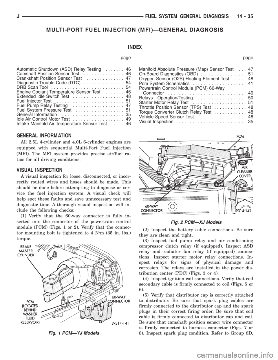
(1) Verify that the 60-way connector is fully in-
serted into the connector of the powertrain control
module (PCM) (Figs. 1 or 2). Verify that the connec-
tor mounting bolt is tightened to 4 Nzm (35 in. lbs.)
torque.(2) Inspect the battery cable connections. Be sure
they are clean and tight.
(3) Inspect fuel pump relay and air conditioning
compressor clutch relay (if equipped). Inspect ASD
relay and radiator fan relay (if equipped) connec-
tions. Inspect starter motor relay connections. In-
spect relays for signs of physical damage and
corrosion. The relays are installed in the power dis-
tribution center (PDC) (Figs. 3 or 4).
(4) Inspect ignition coil connections. Verify that coil
secondary cable is firmly connected to coil (Figs. 5 or
6).
(5) Verify that distributor cap is correctly attached
to distributor. Be sure that spark plug cables are
firmly connected to the distributor cap and the spark
plugs in their correct firing order. Be sure that coil
cable is firmly connected to distributor cap and coil.
Be sure that camshaft position sensor wire connector
is firmly connected to harness connector (Figs. 7 or
8). Inspect spark plug condition. Refer to Group 8D,
Fig. 1 PCMÐYJ Models
Fig. 2 PCMÐXJ Models
JFUEL SYSTEM GENERAL DIAGNOSIS 14 - 35
Page 2024 of 2158
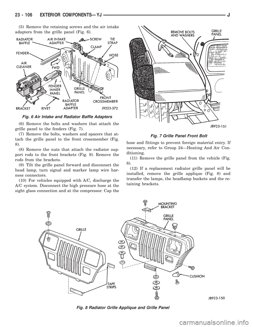
(5) Remove the retaining screws and the air intake
adapters from the grille panel (Fig. 6).
(6) Remove the bolts and washers that attach the
grille panel to the fenders (Fig. 7).
(7) Remove the bolts, washers and spacers that at-
tach the grille panel to the front crossmember (Fig.
8).
(8) Remove the nuts that attach the radiator sup-
port rods to the front brackets (Fig. 9). Remove the
rods from the brackets.
(9) Tilt the grille panel forward and disconnect the
head lamp, turn signal and marker lamp wire har-
ness connectors.
(10) For vehicles equipped with A/C, discharge the
A/C system. Disconnect the high pressure hose at the
sight glass connection and at the compressor. Cap thehose and fittings to prevent foreign material entry. If
necessary, refer to Group 24ÐHeating And Air Con-
ditioning.
(11) Remove the grille panel from the vehicle (Fig.
8).
(12) If a replacement radiator grille panel will be
installed, remove the grille applique (Fig. 8) and
transfer the lamps, the headlamp buckets and the re-
taining brackets.
Fig. 7 Grille Panel Front Bolt
Fig. 8 Radiator Grille Applique and Grille Panel
Fig. 6 Air Intake and Radiator Baffle Adapters
23 - 106 EXTERIOR COMPONENTSÐYJJ
Page 2090 of 2158
oil until you are ready to use it. Install the cap im-
mediately after using. Store the oil only in a clean
moisture-free container.
Keep service tools and the work area clean. Con-
tamination of A/C system through careless work hab-
its must be avoided.
COOLING SYSTEM
To maintain the performance level of the heating/
air conditioning system, the engine cooling system
must be properly maintained.
The use of a bug screen is not recommended. Any
obstructions in front of the radiator or condenser can
reduce the performance of the A/C and cooling sys-
tem. If a bug screen is used it must be cleaned fre-
quently.
COOLANT PRECAUTIONS
WARNING: ANTIFREEZE IS AN ETHYLENE GLYCOL
BASE COOLANT AND IS HARMFUL IF SWAL-
LOWED OR INHALED. IF SWALLOWED, DRINK
TWO GLASSES OF WATER AND INDUCE VOMIT-
ING. IF INHALED, MOVE TO FRESH AIR AREA.
SEEK MEDICAL ATTENTION IMMEDIATELY.
WARNING: WASH SKIN AND CLOTHING THOR-
OUGHLY AFTER COMING IN CONTACT WITH ETH-
YLENE GLYCOL.
WARNING: KEEP OUT OF REACH OF CHILDREN
AND PETS.
WARNING: DO NOT OPEN A COOLING SYSTEM
WHEN THE ENGINE IS AT RUNNING TEMPERA-
TURE. PERSONAL INJURY CAN RESULT.WARNING: DO NOT STORE IN OPEN OR UN-
MARKED CONTAINERS.
WARNING: HOT ENGINE COOLANT CAN CAUSE
SEVERE BURNS. DO NOT OPEN THE RADIATOR
DRAIN COCK WHEN THE COOLING SYSTEM IS
HOT AND PRESSURIZED. ALLOW THE COOLANT
TO DECREASE TO ROOM TEMPERATURE BEFORE
STARTING REPAIR OPERATIONS.
The engine cooling system is designed to develop
internal pressure of 97 to 124 kPa (14 to 18 psi). Al-
low the vehicle 15 minutes to cool down (or until a
safe temperature and pressure are attained) before
opening the cooling system. Refer to Group 7, Cooling
System.REFRIGERANT HOSES/TUBES PRECAUTIONS
Kinks or sharp bends in the refrigerant tubing or
hoses will reduce the capacity of the entire system.
High pressures are produced in the system when it is
operating. Extreme care must be exercised to make
sure that all connections are pressure tight. Dirt and
moisture can enter the system when it is opened for
repair.
A good rule for the flexible hose lines is to keep the
radius of all bends at least 10 times the diameter of
the hose. Sharp bends will reduce the flow of refrig-
erant. The flexible hose lines should be routed so
they are at least 80 mm (3 inches) from the exhaust
manifold. It is a good practice to inspect all flexible
hose lines at least once a year to make sure they are
in good condition and properly routed.
24 - 10 HEATING AND AIR CONDITIONINGJ
Page 2114 of 2158
(11) Connect the heater hoses.
(12) Fill cooling system.
FRESH AIR DOOR VACUUM MOTOR
REMOVAL
(1) Remove glove box and assist handle.
(2) Disconnect vacuum hose from the motor.
(3) Remove motor lever retaining clip.
(4) Remove motor attaching nuts and remove the
motor from the fresh air duct.
INSTALLATION
(1) Position motor on fresh air duct and install the
motor attaching nuts.
(2) Align motor lever with the air door lever and
install the lever retaining clip.
(3) Connect vacuum hose to the motor.
(4) Install glove box and assist handle.
FRESH AIR INTAKE DUCT
REVIEW WARNINGS AND CAUTIONS IN
THIS GROUP BEFORE PERFORMING THIS
OPERATION.
REMOVAL
(1) Drain coolant from the radiator.
(2) Disconnect heater hoses.
(3) Remove nuts attaching the heater housing
studs to the dash panel from inside the engine com-
partment.
(4) Disconnect speedometer cable.
(5) Remove glove box and assist handle.
(6) Tilt heater housing back and pull it rearward
and out from under the instrument panel.
(7) Disconnect vent cables.
(8) Remove windshield bracket bolts and lower
windshield.
(9) Remove fresh air intake grille from the cowl.
(10) Remove fresh air intake duct.
INSTALLATION
(1) Install fresh air intake duct.
(2) Install defroster nozzle and duct.
(3) Raise and secure the windshield.
(4) Install fresh air grille on the cowl.
(5) Install vent cables.
(6) Position heater housing on the dash panel. Be
sure all the housing studs extend through the dash
panel.
(7) Install seals on the blower motor and heater
core inlet and outlet tubes.
(8) Install nuts on the heater housing studs.
CAUTION: DO NOT over tighten the attaching nuts.
The housing could become distorted causing air
leaks and improper heater door operation. Tightenthe nuts alternately and evenly until 2 stud threads
are visible beyond each nut.
(9) Install glove box and assist handle.
(10) Connect speedometer cable.
(11) Connect heater hoses.
(12) Fill cooling system.
TEMPERATURE CONTROL THERMOSTAT
REMOVAL
(1) Remove mounting bolts and lower the evapora-
tor housing.
(2) Remove the attaching screws holding the top
and bottom housings together.
(3) Separate the housings.
(4) Remove the thermostat.
INSTALLATION
(1) Install temperature control thermostat. Insert
thermostat capillary tube into the evaporator coil a
minimum of 50 mm (2 inch).
CAUTION: Handle the tube with care to avoid bends
or kinks that could cause the thermostat to mal-
function.
(2) Assemble the housing and install the attaching
screws. DO NOT over tighten the attaching screws.
(3) Install the evaporator housing.
A/C CONDENSER
REVIEW WARNINGS AND CAUTIONS IN
THIS GROUP BEFORE PERFORMING THIS
OPERATION.
REMOVAL
(1) Recover refrigerant from A/C system.
(2) Drain the radiator.
(3) Remove fan shroud and radiator.
(4) Disconnect A/C line from the condenser.
(5) Remove condenser attaching screws and tilt the
bottom of the condenser toward the engine.Plug all
the condenser openings to prevent entry of dirt
or moisture.
(6) Working from under the vehicle, disconnect the
receiver-drier to-evaporator hose fitting from the re-
ceiver-drier.
(7) Remove condenser and receiver-drier as an as-
sembly.
(8) Remove receiver-drier from the condenser, if
necessary.
INSTALLATION
Add 30 ml (1 fluid oz.) of refrigerant oil to the A/C
system if the condenser is replaced.
(1) Attach receiver-drier to the condenser.
(2) Install condenser and connect A/C line to the
receiver-drier.
24 - 34 HEATING AND AIR CONDITIONINGJ
Page 2115 of 2158
(3) Install condenser attaching screws.
(4) Connect condenser A/C line.
(5) Install radiator and fan shroud.
(6) Fill coolant system (Refer to cooling for proper
procedure).
(7) Evacuate, charge and leak test the air condi-
tioning system.
RECEIVER-DRIER REPLACEMENT
REVIEW ALL WARNINGS AND CAUTIONS IN
THIS GROUP BEFORE PERFORMING THIS
OPERATION.
REMOVAL
(1) Recover refrigerant from A/C system.
(2) Disconnect A/C lines from the receiver-drier.
(3) Remove receiver-drier attaching screws and re-
move receiver-drier.
INSTALLATION
(1) Position receiver-drier in place and install re-
ceiver-drier attaching screws.
(2) Connect A/C lines to receiver-drier.
(3) Evacuate, charge and leak test the air condi-
tioning system.
EVAPORATOR AND HOUSING
REVIEW ALL WARNINGS AND CAUTIONS IN
THIS GROUP BEFORE PERFORMING THIS
OPERATION.
REMOVAL
(1) Recover refrigerant from A/C system.
(2) Disconnect A/C lines.
(3) Remove hose clamps and dash grommet retain-
ing screws.
(4) Remove the evaporator housing-to-instrument
panel attaching screws and the housing mounting
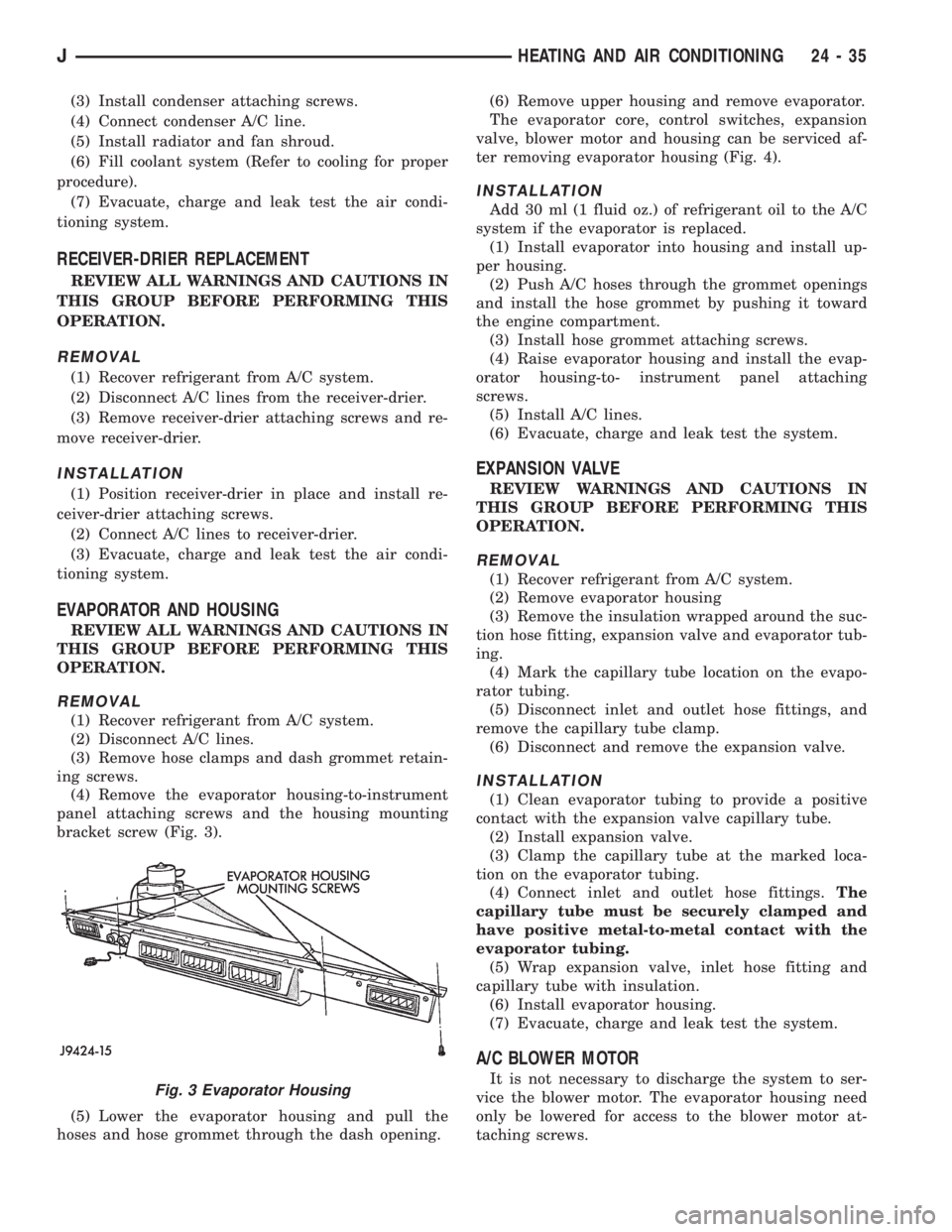
bracket screw (Fig. 3).
(5) Lower the evaporator housing and pull the
hoses and hose grommet through the dash opening.(6) Remove upper housing and remove evaporator.
The evaporator core, control switches, expansion
valve, blower motor and housing can be serviced af-
ter removing evaporator housing (Fig. 4).
INSTALLATION
Add 30 ml (1 fluid oz.) of refrigerant oil to the A/C
system if the evaporator is replaced.
(1) Install evaporator into housing and install up-
per housing.
(2) Push A/C hoses through the grommet openings
and install the hose grommet by pushing it toward
the engine compartment.
(3) Install hose grommet attaching screws.
(4) Raise evaporator housing and install the evap-
orator housing-to- instrument panel attaching
screws.
(5) Install A/C lines.
(6) Evacuate, charge and leak test the system.
EXPANSION VALVE
REVIEW WARNINGS AND CAUTIONS IN
THIS GROUP BEFORE PERFORMING THIS
OPERATION.
REMOVAL
(1) Recover refrigerant from A/C system.
(2) Remove evaporator housing
(3) Remove the insulation wrapped around the suc-
tion hose fitting, expansion valve and evaporator tub-
ing.
(4) Mark the capillary tube location on the evapo-
rator tubing.
(5) Disconnect inlet and outlet hose fittings, and
remove the capillary tube clamp.
(6) Disconnect and remove the expansion valve.
INSTALLATION
(1) Clean evaporator tubing to provide a positive
contact with the expansion valve capillary tube.
(2) Install expansion valve.
(3) Clamp the capillary tube at the marked loca-
tion on the evaporator tubing.
(4) Connect inlet and outlet hose fittings.The
capillary tube must be securely clamped and
have positive metal-to-metal contact with the
evaporator tubing.
(5) Wrap expansion valve, inlet hose fitting and
capillary tube with insulation.
(6) Install evaporator housing.
(7) Evacuate, charge and leak test the system.
A/C BLOWER MOTOR
It is not necessary to discharge the system to ser-
vice the blower motor. The evaporator housing need
only be lowered for access to the blower motor at-
taching screws.Fig. 3 Evaporator Housing
JHEATING AND AIR CONDITIONING 24 - 35
Page 2128 of 2158
BUMPERÐXJ, LIFTGATE LICENSE PLATE
SCREW ANCHOR.....................23-65
BUMPERÐXJ, REAR SEATBACK LATCH
STRIKER...........................23-84
BUMPERS......................13-16,13-5
BUS, CCD; FUEL/IGNITION (XJ).......8W-30-5
BUSHING AND PISTON CLEARANCE,
AW-4 .............................21-339
BUSHING REPLACEMENT, AXLE......2-12,2-34
BUSHING REPLACEMENT, LEAF SPRING
EYE; FRONT SUSPENSION AND AXLE.....2-17
BUSHING REPLACEMENT, LEAF SPRING
EYE; REAR SUSPENSION AND AXLES . . . 3-5,3-7
BUSHINGS, CLUTCH AND BRAKE PEDAL . . . 0-22
BUZZER, COMBINATION; INTERIOR
LIGHTING (YJ)....................8W-44-1
BUZZER MODULE.................8U-1,8U-2
BUZZER MODULE SCHEMATIC - YJ.......8U-4
CABLE, ACCELERATOR PEDAL AND
THROTTLE.....................14-17,14-58
CABLE ADJUSTMENT, PARK INTERLOCK . 21-195
CABLE ADJUSTMENT, SHIFT...........21-195
CABLE ADJUSTMENT, TRANSMISSION
THROTTLE.........................21-194
CABLE ADJUSTMENT, TRANSMISSION
THROTTLE VALVE....................21-71
CABLE ADJUSTMENT (XJ), PARK
INTERLOCK........................21-101
CABLE ADJUSTMENT (XJ), SHIFT.......21-100
CABLE ADJUSTMENT (XJ/YJ), THROTTLE
VALVE..............................21-101
CABLE REMOVE/INSTALL, SERVO.......8H-10
CABLE REPLACEMENT, TRANSMISSION
THROTTLE.........................21-193
CABLE REPLACEMENT (XJ), PARKING
BRAKE REAR.........................5-67
CABLE REPLACEMENT (YJ), PARKING
BRAKE FRONT........................5-67
CABLE REPLACEMENT (YJ), PARKING
BRAKE REAR.........................5-68
CABLE REPLACEMENTÐXJ, LATCH
RELEASE...........................23-11
CABLE RESISTANCE, SPARK PLUG......8D-14
CABLE, SERVO.......................8H-1
CABLE, SPEEDOMETER.................0-33
CABLE TENSIONER ADJUSTMENT
(XJ/YJ), PARKING BRAKE...............5-69
CABLE TENSIONER REPLACEMENT (XJ),
PARKING BRAKE......................5-66
CABLE, THROTTLE...................14-17
CABLE/LINKAGE ADJUSTMENT,
GEARSHIFT.........................21-71
CABLES, DISTRIBUTOR CAP AND
ROTOR, IGNITION.....................0-20
CABLES, SPARK PLUG SECONDARY.....8D-14,
8D-24
CABLES, VENT DOOR CONTROL.........24-32
CALIBRATION, COMPASS...............8C-5
CALIPER ASSEMBLY...................5-50
CALIPER CLEANING AND INSPECTION.....5-50
CALIPER DISASSEMBLY................5-48
CALIPER INSTALLATION................5-51
CALIPER OPERATION AND WEAR
COMPENSATION......................5-45
CALIPER REMOVAL....................5-48
CAMSHAFT......................9-32,9-74
CAMSHAFT PIN REPLACEMENT......9-34,9-75
CAMSHAFT POSITION SENSOR; FUEL
SYSTEM............................14-60
CAMSHAFT POSITION SENSOR;
FUEL/IGNITION (XJ)................8W-30-3
CAMSHAFT POSITION SENSOR;
FUEL/IGNITION (YJ)................8W-30-3
CAMSHAFT POSITION SENSOR;
IGNITION SYSTEMS..............8D-17,8D-2
CAMSHAFT POSITION SENSOR;
FUEL/IGNITION (XJ-RHD)............8W-30-3
CAMSHAFT POSITION SENSOR TEST;
FUEL SYSTEM.......................14-46
CAMSHAFT POSITION SENSOR TEST;
IGNITION SYSTEMS
...................8D-6
CAMSHAFT POSITION SENSORÐPCM
INPUT
.............................14-22
(CANADA ONLY)ÐXJ, DAYTIME
RUNNING LIGHTS
....................8L-15
(CANADA ONLY)ÐYJ, DAYTIME
RUNNING LIGHTS
....................8L-30
CANISTER, EVAP
..................25-4,25-7CAP AND ROTOR, IGNITION CABLES,
DISTRIBUTOR........................0-20
CAP, DISTRIBUTOR....................8D-7
CAP, FUEL TANK FILLER TUBE;
EMISSION CONTROL SYSTEMS......25-4,25-7
CAP, FUEL TANK FILLER TUBE; FUEL
SYSTEM............................14-13
CAP, RADIATOR PRESSURE.............7-25
CAPACITIES, COOLING SYSTEM..........7-45
CAPACITIES, FLUID.....................0-3
CAPACITIES, FUEL TANK..........14-13,14-67
CAPACITY TEST, FUEL PUMP............14-7
CAR REPLACEMENT, PITMAN SHAFT
SEALSÐIN.........................19-23
CARDAN (CV), DOUBLE................16-11
CARDAN, SINGLE....................16-10
CARGO BARRIERÐXJ................23-101
CARGO LAMP AND DOME LAMP;
INTERIOR LIGHTING (XJ-RHD)........8W-44-1
CARGO LAMP, COURTESY LAMPS AND
DOME LAMP; INTERIOR LIGHTING (XJ) . 8W-44-1
CARGO LAMPÐXJ...................23-94
CARPET/MATÐXJ, FRONT.............23-99
CARPET/MATÐXJ, REAR.............23-100
CARPETÐYJ.......................23-156
CARPETS AND FLOOR MATSÐXJ.......23-99
CARRIERÐYJ, EXTERNAL SPARE/
WHEEL TIRE.......................23-133
CASE (4WD VEHICLES), TRANSFER........0-24
CASE ASSEMBLY, TRANSFER....21-294,21-319
CASE CHANGES, TRANSFER...........21-307
CASE CLEANING AND INSPECTION,
TRANSMISSION.....................21-125
CASE COVER OIL SEAL REPLACEMENT,
TIMING.........................9-30,9-73
CASE COVER, TIMING..............9-31,9-72
CASE DISASSEMBLY AND OVERHAUL,
TRANSFER...................21-289,21-310
CASE IDENTIFICATION, TRANSFER.....21-284,
21-307
CASE INSTALLATION, TRANSFER . 21-288,21-309
CASE LUBRICANT AND FILL LEVEL,
TRANSFER.........................21-284
CASE, NP231 TRANSFER.......21-283,21-305
CASE, NP242 TRANSFER.......21-307,21-331
CASE OVERHAUL, FIRST-REVERSE
BRAKE PISTON AND TRANSMISSION....21-247
CASE REMOVAL, TRANSFER.....21-287,21-309
CASE SKID PLATE, TRANSFER......13-15,13-3
CASE SPECIFICATIONS, TRANSMISSION/
TRANSFER.........................21-333
CATALYTIC CONVERTER............11-1,11-4
CATALYTIC CONVERTOR................25-1
CAUTIONS, AND WARNINGS, NOTES;
WIRING DIAGRAMSÐGENERAL
INFORMATION (XJ)...................8W-1
CCD BUS; FUEL/IGNITION (XJ)........8W-30-5
CENTER HIGH MOUNTED STOP LAMP
(CHMSL)ÐXJ.......................8L-12
CENTER HIGH MOUNTED STOP LAMP
(CHMSL)ÐYJ.......................8L-28
CERTIFICATION LABEL, VEHICLE SAFETY . Intro.-4
CHAIN AND SPROCKETS, TIMING....9-31,9-73
CHANGE AND FILTER REPLACEMENT,
ENGINE OIL
..........................0-16
CHANGE, LUBRICANT; FRONT
SUSPENSION AND AXLE
................2-23
CHANGE, LUBRICANT; REAR
SUSPENSION AND AXLES
...........3-13,3-31
CHANGE, REFILLING AFTER OVERHAUL
OR FLUID/FILTER
..............21-100,21-182
CHANGES AND PARTS
INTERCHANGEABILITY, TRANSMISSION
. . . 21-67
CHANGES, TRANSFER CASE
...........21-307
CHANNEL REPLACEMENTÐYJ, DOOR
FRAME GLASS
......................23-142
CHARGING, BATTERY
..................8A-7
CHARGING REFRIGERANT SYSTEM
......24-11
CHARGING SYSTEM; BATTERY/
STARTING/CHARGING SYSTEMS
DIAGNOSTICS
.......................8A-17
CHARGING SYSTEM; CHARGING
SYSTEM (XJ)
.....................8W-20-1
CHARGING SYSTEM; CHARGING
SYSTEM (XJ-RHD)
.................8W-20-1
CHARGING SYSTEM; CHARGING
SYSTEM (YJ)
.....................8W-20-1CHARGING SYSTEM INDICATOR LAMP;
INSTRUMENT CLUSTER (XJ).........8W-40-3
CHARGING SYSTEM SPECIFICATIONS....8A-23
CHARGING TIME TABLE, BATTERY........8A-8
CHART, MAIN BEARING FITTING......9-48,9-90
CHART, XJ PERFORMANCE
TEMPERATURE AND PRESSURE.........24-13
CHART, YJ PERFORMANCE
TEMPERATURE AND PRESSURE.........24-13
CHARTÐAX 15 MANUAL
TRANSMISSION, SELECTIVE SNAP
RING.............................21-334
CHARTS, BRAKELINE..................5-12
CHARTS, DIAGNOSIS GUIDES...........21-77
CHARTS, GEARTRAIN OPERATION AND
APPLICATION.......................21-169
CHARTS, INSPECTION AND DIAGNOSIS.....6-4
CHASSIS AND BODY COMPONENTS.......0-28
CHASSIS COMPONENT AND WHEEL
BEARING LUBRICANTS.................0-28
CHECK VALVE TEST, POWER BOOSTER.....5-9
CHECKING FLUID LEVEL AND
CONDITION........................21-182
CHECKS, PRELIMINARY.................7-5
CHIME/BUZZER MODULE; INTERIOR
LIGHTING (XJ)....................8W-44-2
CHIME/BUZZER MODULE; INTERIOR
LIGHTING (XJ-RHD)................8W-44-2
CHMSL LAMPS, STOP LAMPS; REAR
LIGHTING (XJ)....................8W-51-1
CHMSL LAMPS, STOP LAMPS; REAR
LIGHTING (XJ-RHD)................8W-51-1
CHMSL LAMPS, STOP LAMPS; REAR
LIGHTING (YJ)....................8W-51-1
(CHMSL)ÐXJ, CENTER HIGH MOUNTED
STOP LAMP.........................8L-12
(CHMSL)ÐYJ, CENTER HIGH MOUNTED
STOP LAMP.........................8L-28
CIGAR LIGHTER; HORN/CIGAR LIGHTER . . . 8E-1
CIGAR LIGHTER; HORN/CIGAR LIGHTER
(YJ).............................8W-41-1
CIGAR LIGHTER; INSTRUMENT CLUSTER
(XJ).............................8W-40-1
CIRCUIT IDENTIFICATION; WIRING
DIAGRAMSÐGENERAL INFORMATION
(XJ)...............................8W-1
CIRCUIT REMOVE/INSTALL, PRINTED....8E-19,
8E-40
CIRCUIT SENSEÐPCM INPUT, IGNITION . . 14-23
CIRCUIT VOLTAGE, OPEN...............8A-6
CLAMPS, FUEL TUBES/LINES/HOSES . 14-62,14-9
CLASSIFICATION OF LUBRICANTS.........0-2
CLASSIFICATIONS AND RATINGS,
BATTERY...........................8A-23
CLEANER, AIR.......................14-29
CLEANER ELEMENT, AIR; EMISSION
CONTROL SYSTEMS...................25-7
CLEANER ELEMENT, AIR; FUEL SYSTEM . . 14-59
CLEANER ELEMENT, AIR; LUBRICATION
AND MAINTENANCE...................0-18
CLEANER HOUSING, AIR...............14-58
CLEANING AND INSPECTION, CALIPER....5-50
CLEANING AND INSPECTION, GEAR......19-42
CLEANING AND INSPECTION,
TRANSMISSION CASE................21-125
CLEANING OF TIRES...................22-2
CLEANING/INSPECTION; FRONT
SUSPENSION AND AXLE
................2-37
CLEANING/INSPECTION; REAR
SUSPENSION AND AXLES
...............3-20
CLEANING/REVERSE FLUSHING,
COOLING SYSTEM
....................7-22
CLEARANCE AND RAMP ANGLE,
GROUND
............................0-11
CLEARANCE, AW-4 BUSHING AND
PISTON
...........................21-339
CLOCKSPRING
.......................19-51
CLUSTER AND GAUGE HOUSINGSÐYJ,
INSTRUMENT
......................23-151
CLUSTER ASSEMBLY REMOVE/INSTALL
. . 8E-17,
8E-35
CLUSTER BEZELÐXJ, INSTRUMENT
.....23-80
CLUSTER BEZELÐYJ, INSTRUMENT
....23-151
CLUSTER CONNECTORS (RHD)
.........8E-11
CLUSTER, GAUGE PACKAGE
.......8E-31,8E-43
CLUSTER GROUND; INSTRUMENT
CLUSTER (XJ)
.....................8W-40-3
4 INDEXJ
Description Group-Page Description Group-Page Description Group-Page
Page 2130 of 2158
CONTENTS; INSTRUMENT PANEL AND
GAUGESÐXJ........................8E-24
CONTENTS; LAMPS...................8L-19
CONTINUITY (LEFT POSITION), POWER
MIRROR SWITCH.....................8T-3
CONTINUITY, POWER SEAT SWITCH......8R-2
CONTINUITY (RIGHT POSITION), POWER
MIRROR SWITCH.....................8T-3
CONTINUITY TESTS, IGNITION SWITCH . . . 8D-30
CONTROL AND DISPLAY SYMBOLS,
INTERNATIONAL VEHICLE.............Intro.-5
CONTROL AND DISPLAY SYMBOLS,
VEHICLE.........................Intro.-10
CONTROL CABLES, VENT DOOR.........24-32
CONTROL DIAGNOSTIC TROUBLE CODE,
SPEED..............................8H-5
CONTROL, FUEL PUMP ELECTRICAL......14-5
CONTROL (IAC) MOTOR, IDLE AIR; FUEL
SYSTEM............................14-62
CONTROL (IAC) MOTOR, IDLE AIR;
FUEL/IGNITION (XJ)................8W-30-2
CONTROL (IAC) MOTOR, IDLE AIR;
FUEL/IGNITION (YJ)................8W-30-2
CONTROL (IAC) MOTOR, IDLE AIR;
FUEL/IGNITION (XJ-RHD)............8W-30-2
CONTROL (IAC) MOTORÐPCM OUTPUT,
IDLE AIR...........................14-27
CONTROL INFORMATION (VECI) LABEL,
VEHICLE EMISSION....................25-1
CONTROL MODULE (PCM) 60-WAY
CONNECTOR, POWERTRAIN............14-40
CONTROL MODULE (PCM),
POWERTRAIN; EMISSION CONTROL
SYSTEMS...........................25-7
CONTROL MODULE (PCM),
POWERTRAIN; FUEL SYSTEM......14-20,14-64
CONTROL MODULE (PCM),
POWERTRAIN; IGNITION SYSTEMS......8D-11,
8D-23,8D-5
CONTROL MODULE, POWERTRAIN . . . 8H-1,8H-7
CONTROL MODULE (TCM) SERVICE,
TRANSMISSION.....................21-183
CONTROL MODULE, TRANSMISSION;
TRANSMISSION CONTROLS (XJ-RHD) . . 8W-31-1
CONTROL MODULEÐ4.0L ENGINE ONLY,
TRANSMISSION; TRANSMISSION
CONTROLS (XJ)...................8W-31-1
CONTROL MOTOR TEST, IDLE AIR.......14-49
CONTROL PANEL LAMP, ACCESSORY
LAMP AND HEATER; INTERIOR
LIGHTING (YJ)....................8W-44-1
CONTROL REPLACEMENT, HEATER.......24-32
CONTROL REPLACEMENT, HEATER AND
A/C................................24-23
CONTROL SERVO REMOVE/INSTALL,
SPEED..............................8H-9
CONTROL SERVO, SPEED..........8H-1,8H-6
CONTROL SWITCH REMOVE/INSTALL,
SPEED..............................8H-9
CONTROL SWITCH, SPEED.........8H-1,8H-6
CONTROL SYSTEM, EMISSION...........0-20
CONTROL SYSTEM, EVAP
(EVAPORATION)......................25-4
CONTROL SYSTEM MAINTENANCE,
EMISSION............................0-4
CONTROL THERMOSTAT, TEMPERATURE . . 24-34
CONTROL, THERMOSTATIC.............24-16
CONTROL UNIT (ECU), ELECTRONIC......5-34
CONTROL UNIT (HCU), HYDRAULIC.......5-33
CONTROL UNIT, HYDRAULIC; ANTI-LOCK
BRAKES (XJ)......................8W-32-2
CONTROL UNIT, HYDRAULIC; ANTI-LOCK
BRAKES (XJ-RHD).................8W-32-2
CONTROL UNIT, HYDRAULIC; ANTI-LOCK
BRAKES (YJ)......................8W-32-2
CONTROL VALVE FITTING O-RING SEAL,
FLOW..............................19-14
CONTROL, VEHICLE SPEED; VEHICLE
SPEED CONTROL (XJ)..............8W-33-1
CONTROL, VEHICLE SPEED; VEHICLE
SPEED CONTROL (XJ-RHD)..........8W-33-1
CONTROLÐPCM INPUT, SPEED
.........14-25
CONTROLÐPCM OUTPUT, SPEED
.......14-29
CONTROLS AND COMPONENTS,
TRANSMISSION
......................21-67
CONTROLS, EMISSION
.................25-4
CONTROLSÐPCM INPUT, AIR
CONDITIONING (A/C)
..................14-21CONTROLSÐXJ VEHICLES, AIR
CONDITIONING......................24-15
CONTROLSÐYJ VEHICLES, AIR
CONDITIONING......................24-16
CONVERSION FORMULAS AND
EQUIVALENT VALUES...............Intro.-11
CONVERSION, METRIC..............Intro.-16
CONVERSION, METRIC AND ENGLISH/
SAE .............................Intro.-11
CONVERTER, CATALYTIC............11-1,11-4
CONVERTER CLUTCH RELAY TEST,
TORQUE............................14-48
CONVERTER CLUTCH RELAY, TORQUE....14-65
CONVERTER CLUTCH RELAYÐPCM
OUTPUT, TORQUE....................14-29
CONVERTER CLUTCH (TCC) SOLENOID
AND RELAY, TORQUE; FUEL/IGNITION
(XJ).............................8W-30-4
CONVERTER CLUTCH (TCC) SOLENOID
AND RELAY, TORQUE; TRANSMISSION
CONTROLS (YJ)...................8W-31-1
CONVERTER CLUTCH (TCC) SOLENOID
AND RELAYÐ2.5L ENGINE ONLY,
TORQUE; TRANSMISSION CONTROLS
(XJ).............................8W-31-1
CONVERTER DIAGNOSIS, TORQUE . 21-86,21-87,
21-88
CONVERTER HOUSING LEAK DIAGNOSIS . . 21-75
CONVERTER INSTALLATION,
TRANSMISSION.....................21-117
CONVERTER INSTALLATION,
TRANSMISSION AND TORQUE.........21-199
CONVERTER REMOVAL, TRANSMISSION . 21-115
CONVERTER REMOVAL, TRANSMISSION
AND TORQUE......................21-198
CONVERTER STALL TEST..............21-74
CONVERTER STALL TEST, TORQUE.....21-178
CONVERTER STATOR CLUTCH
INSPECTION, TORQUE................21-199
CONVERTER, TORQUE...........21-167,21-67
CONVERTERÐPUMP SEALÐDRIVE
PLATE SERVICE.....................21-116
CONVERTOR, CATALYTIC................25-1
COOLANT............................7-20
COOLANT RESERVE/OVERFLOW SYSTEM . . 7-24
COOLANT ROUTING, SYSTEM.............7-1
COOLANT TEMPERATURE GAUGE,
ENGINE; INSTRUMENT CLUSTER (XJ) . . 8W-40-1
COOLANT TEMPERATURE SENSOR.......25-7
COOLANT TEMPERATURE SENSOR,
ENGINE; FUEL SYSTEM................14-60
COOLANT TEMPERATURE SENSOR,
ENGINE; FUEL/IGNITION (XJ).........8W-30-3
COOLANT TEMPERATURE SENSOR,
ENGINE; FUEL/IGNITION (YJ).........8W-30-3
COOLANT TEMPERATURE SENSOR,
ENGINE; IGNITION SYSTEMS.......8D-19,8D-5
COOLANT TEMPERATURE SENSOR,
ENGINE; FUEL/IGNITION (XJ-RHD).....8W-30-3
COOLANT TEMPERATURE SENSOR TEST,
ENGINE; FUEL SYSTEM................14-46
COOLANT TEMPERATURE SENSOR TEST,
ENGINE; IGNITION SYSTEMS............8D-9
COOLANT TEMPERATURE SENSORÐ
PCM INPUT, ENGINE
..................14-23
COOLANT TEMPERATURE WARNING
LAMP, ENGINE; INSTRUMENT
CLUSTER (XJ)
.....................8W-40-1
COOLANT TEMPERATURE WARNING
LAMP, ENGINE; INSTRUMENT
CLUSTER (XJ-RHD)
................8W-40-1
COOLER FLOW TESTING,
TRANSMISSION
.....................21-113
COOLER LINE AND FITTING SERVICE,
TRANSMISSION
.....................21-111
COOLER LINE FITTINGS, TRANSMISSION
. 21-197
COOLER REVERSE FLUSHING,
TRANSMISSION
.....................21-114
COOLER SERVICE, TRANSMISSION
.....21-196
COOLERS, TRANSMISSION OIL
..........7-36
COOLING FANÐXJ MODELS WITH 4.0L
6-CYLINDER ENGINE, AUXILIARY
ELECTRIC
...........................7-35
COOLING SYSTEM; COOLING SYSTEM
......7-1
COOLING SYSTEM; HEATING AND AIR
CONDITIONING
......................24-10
COOLING SYSTEM CAPACITIES
..........7-45COOLING SYSTEM CLEANING/REVERSE
FLUSHING...........................7-22
COOLING SYSTEM COMPONENTS.........7-1
COOLING SYSTEM DIAGNOSIS............7-6
COOLING SYSTEM, DRAINING...........7-21
COOLING SYSTEM, ENGINE.............0-18
COOLING SYSTEM FANS................7-32
COOLING SYSTEM FOR LEAKS, TESTING . . . 7-22
COOLING SYSTEM HOSES..............7-32
COOLING SYSTEM, REFILLING...........7-21
CORE AND HOUSING, HEATER..........24-33
CORE, HEATER......................24-26
COURTESY LAMPS AND DOME LAMP,
CARGO LAMP; INTERIOR LIGHTING
(XJ).............................8W-44-1
COURTESY LAMPS AND DOME LAMPS;
INTERIOR LIGHTING (YJ)............8W-44-1
COURTESY LAMPS, READING...........8C-1
COVER AND DISC INSTALLATION,
CLUTCH.............................6-10
COVER AND DISC REMOVAL, CLUTCH.....6-10
COVER AND DISC RUNOUT, CLUTCH.......6-3
COVER AND FRAMEÐXJ, BUCKET
SEATBACK..........................23-81
COVER, ENGINE CYLINDER HEAD....9-22,9-64
COVER, FRAME CROSSMEMBER........13-16
COVER OIL SEAL REPLACEMENT,
TIMING CASE....................9-30,9-73
COVER REPLACEMENT, PITMAN SHAFT
AND SIDE..........................19-28
COVER, TIMING CASE..............9-31,9-72
COVERÐXJ, BUCKET SEAT CUSHION....23-81
COVERÐXJ, PARKING BRAKE HANDLE . . . 23-94
COVERÐXJ, REAR SEAT CUSHION......23-82
COVERÐXJ, REAR SEATBACK..........23-84
COVERSÐXJ, B/C-PILLAR AND
LIFTGATE PILLAR TRIM...............23-88
COWL GRILLE AND SCREENÐXJ........23-12
COWL GRILLE AND SCREENÐYJ.......23-109
COWL WEATHERSTRIP SEAL/
CROSSMEMBER AIR DEFLECTORÐXJ....23-11
COWL WEATHERSTRIP SEALÐYJ......23-109
CRANKCASE VENTILATION SYSTEM;
EMISSION CONTROL SYSTEMS..........25-5
CRANKCASE VENTILATION SYSTEM;
LUBRICATION AND MAINTENANCE........0-19
CRANKING SPECIFICATIONS, 2.5L
STARTING SYSTEM COLD..............8A-23
CRANKING SPECIFICATIONS, 4.0L
STARTING SYSTEM COLD..............8A-23
CRANKSHAFT MAIN BEARINGS......9-45,9-87
CRANKSHAFT POSITION SENSOR; FUEL
SYSTEM............................14-60
CRANKSHAFT POSITION SENSOR;
FUEL/IGNITION (XJ)................8W-30-3
CRANKSHAFT POSITION SENSOR;
FUEL/IGNITION (YJ)................8W-30-3
CRANKSHAFT POSITION SENSOR;
IGNITION SYSTEMS..............8D-17,8D-3
CRANKSHAFT POSITION SENSOR;
FUEL/IGNITION (XJ-RHD)............8W-30-3
CRANKSHAFT POSITION SENSOR TEST;
FUEL SYSTEM.......................14-47
CRANKSHAFT POSITION SENSOR TEST;
IGNITION SYSTEMS...................8D-7
CRANKSHAFT POSITION SENSORÐPCM
INPUT.............................14-22
CROSSMEMBER COVER, FRAME........13-16
CROSSMEMBERÐXJ, RADIATOR
SUPPORT...........................23-6
CUSHION AND COVERÐXJ, BUCKET
SEAT ..............................23-81
CUSHION COVERÐXJ, REAR SEAT......23-82
CUSHIONÐXJ, REAR SEAT.............23-82
CUT-OFF SWITCH, LOW-PRESSURE
HIGH-PRESSURE................24-15,24-16
CYCLING CLUTCH SWITCH, FIN
SENSING......................24-15,24-31
CYLINDER AND COMBINATION VALVE
INSTALLATION (WITH ABS), MASTER.....5-20
CYLINDER AND COMBINATION VALVE
REMOVAL (WITH ABS), MASTER.........5-17
CYLINDER BENCH BLEEDING, MASTER
....5-21
CYLINDER BLOCK
.................9-49,9-91
CYLINDER BORES, HONING
..............9-2
CYLINDER, CLUTCH MASTER
............0-22
CYLINDER COMBUSTION PRESSURE
LEAKAGE TEST
........................9-6
6 INDEXJ
Description Group-Page Description Group-Page Description Group-Page