1995 JEEP YJ change wheel
[x] Cancel search: change wheelPage 1474 of 2158
²Have at least a 1/2 degree continuous operating
(propeller shaft) angle
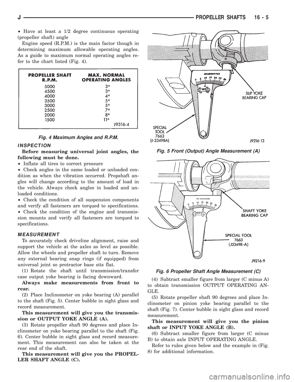
Engine speed (R.P.M.) is the main factor though in
determining maximum allowable operating angles.
As a guide to maximum normal operating angles re-
fer to the chart listed (Fig. 4).
INSPECTION
Before measuring universal joint angles, the
following must be done.
²Inflate all tires to correct pressure
²Check angles in the same loaded or unloaded con-
dition as when the vibration occurred. Propshaft an-
gles will change according to the amount of load in
the vehicle. Always check angles in loaded and un-
loaded conditions.
²Check the condition of all suspension components
and verify all fasteners are torqued to specifications.
²Check the condition of the engine and transmis-
sion mounts and verify all fasteners are torqued to
specifications.
MEASUREMENT
To accurately check driveline alignment, raise and
support the vehicle at the axles as level as possible.
Allow the wheels and propeller shaft to turn. Remove
any external bearing snap rings (if equipped) from
universal joint so protractor base sits flat.
(1) Rotate the shaft until transmission/transfer
case output yoke bearing is facing downward.
Always make measurements from front to
rear.
(2) Place Inclinometer on yoke bearing (A) parallel
to the shaft (Fig. 5). Center bubble in sight glass and
record measurement.
This measurement will give you the transmis-
sion or OUTPUT YOKE ANGLE (A).
(3) Rotate propeller shaft 90 degrees and place In-
clinometer on yoke bearing parallel to the shaft (Fig.
6). Center bubble in sight glass and record measure-
ment. This measurement can also be taken at the
rear end of the shaft.
This measurement will give you the PROPEL-
LER SHAFT ANGLE (C).(4) Subtract smaller figure from larger (C minus A)
to obtain transmission OUTPUT OPERATING AN-
GLE.
(5) Rotate propeller shaft 90 degrees and place In-
clinometer on pinion yoke bearing parallel to the
shaft (Fig. 7). Center bubble in sight glass and record
measurement.
This measurement will give you the pinion
shaft or INPUT YOKE ANGLE (B).
(6) Subtract smaller figure from larger (C minus
B) to obtain axle INPUT OPERATING ANGLE.
Refer to rules given below and the example in (Fig.
8) for additional information.
Fig. 4 Maximum Angles and R.P.M.
Fig. 5 Front (Output) Angle Measurement (A)
Fig. 6 Propeller Shaft Angle Measurement (C)
JPROPELLER SHAFTS 16 - 5
Page 1500 of 2158
STEERING LINKAGEÐXJ
INDEX
page page
Drag Link............................... 16
Pitman Arm.............................. 17
Service Information........................ 16Steering Damper.......................... 17
TieRod ................................ 16
SERVICE INFORMATION
The steering linkage consists of a pitman arm, drag
link, tie rod, and steering damper. Adjustment
sleeves are used on the tie rod and drag link for toe
and steering wheel alignment.
Refer to Group 2, Front Suspension and Axle for
additional information.
The tie-rod end ball stud seals should be inspected
during all oil changes.
A damaged ball stud seal requires removal of the
seal. Inspect the tie-rod end ball stud at the throat
opening. Check for lubricant loss, contamination, ball
stud wear or corrosion. If these conditions exist, re-
place the tie-rod. A replacement seal can be installed
if lubricant is in good condition. Otherwise, a com-
plete replacement ball stud end should be installed.
Lubricate the tie-rod end with MOPARtMulti-Mile-
age Lubricant, or equivalent product.
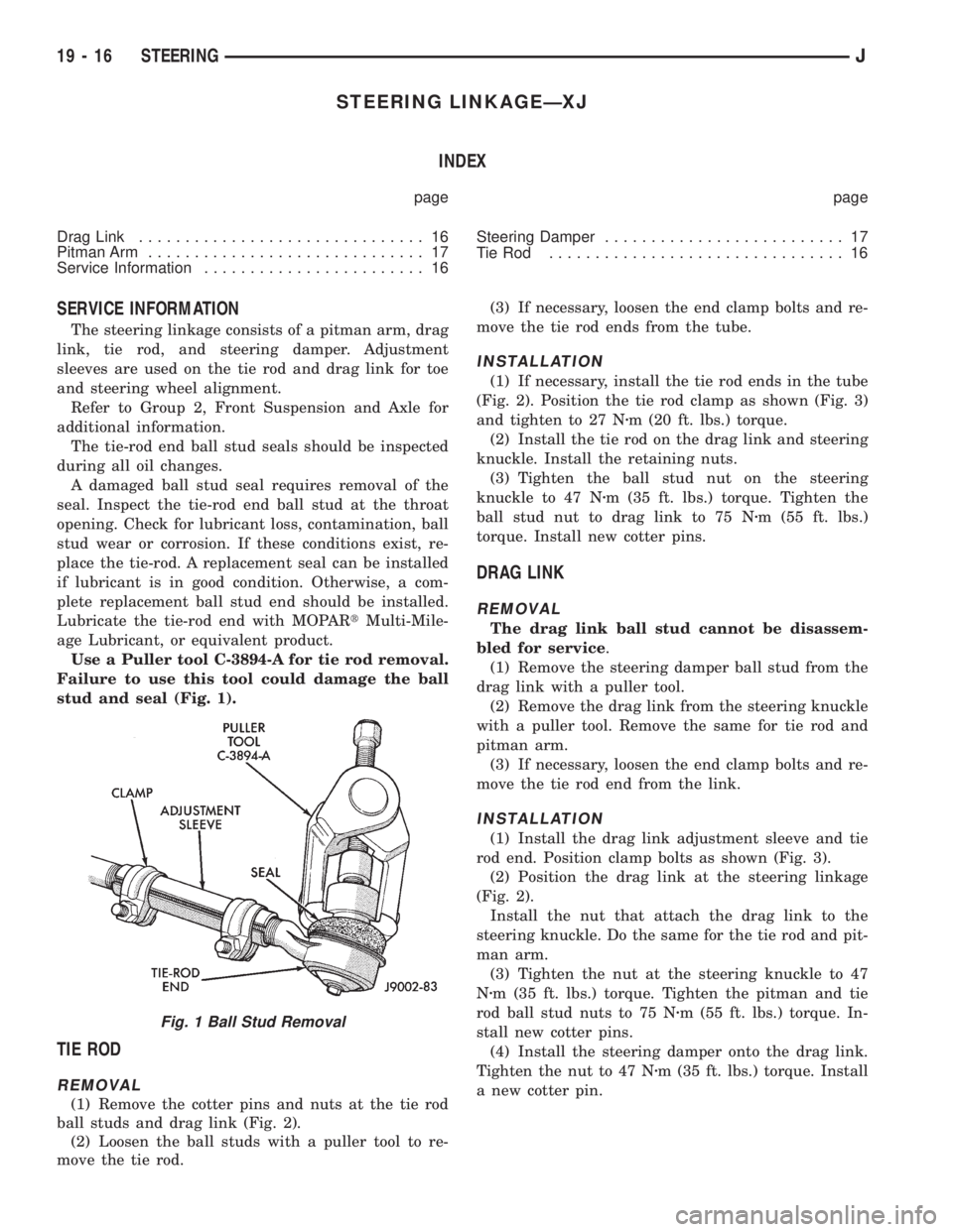
Use a Puller tool C-3894-A for tie rod removal.
Failure to use this tool could damage the ball
stud and seal (Fig. 1).
TIE ROD
REMOVAL
(1) Remove the cotter pins and nuts at the tie rod
ball studs and drag link (Fig. 2).
(2) Loosen the ball studs with a puller tool to re-
move the tie rod.(3) If necessary, loosen the end clamp bolts and re-
move the tie rod ends from the tube.
INSTALLATION
(1) If necessary, install the tie rod ends in the tube
(Fig. 2). Position the tie rod clamp as shown (Fig. 3)
and tighten to 27 Nzm (20 ft. lbs.) torque.
(2) Install the tie rod on the drag link and steering
knuckle. Install the retaining nuts.
(3) Tighten the ball stud nut on the steering
knuckle to 47 Nzm (35 ft. lbs.) torque. Tighten the
ball stud nut to drag link to 75 Nzm (55 ft. lbs.)
torque. Install new cotter pins.
DRAG LINK
REMOVAL
The drag link ball stud cannot be disassem-
bled for service.
(1) Remove the steering damper ball stud from the
drag link with a puller tool.
(2) Remove the drag link from the steering knuckle
with a puller tool. Remove the same for tie rod and
pitman arm.
(3) If necessary, loosen the end clamp bolts and re-
move the tie rod end from the link.
INSTALLATION
(1) Install the drag link adjustment sleeve and tie
rod end. Position clamp bolts as shown (Fig. 3).
(2) Position the drag link at the steering linkage
(Fig. 2).
Install the nut that attach the drag link to the
steering knuckle. Do the same for the tie rod and pit-
man arm.
(3) Tighten the nut at the steering knuckle to 47
Nzm (35 ft. lbs.) torque. Tighten the pitman and tie
rod ball stud nuts to 75 Nzm (55 ft. lbs.) torque. In-
stall new cotter pins.
(4) Install the steering damper onto the drag link.
Tighten the nut to 47 Nzm (35 ft. lbs.) torque. Install
a new cotter pin.
Fig. 1 Ball Stud Removal
19 - 16 STEERINGJ
Page 1503 of 2158
STEERING LINKAGEÐYJ
INDEX
page page
Drag Link............................... 20
Pitman Arm.............................. 20
Service Information........................ 19Steering Damper.......................... 20
TieRod ................................ 19
SERVICE INFORMATION
The steering linkage consists of a pitman arm, drag
link, tie rod, and steering damper. Adjustment
sleeves are used on the tie rod and drag link for toe
and steering wheel alignment.
Refer to Group 2, Front Suspension and Axle for
additional information.The tie-rod end ball stud seals should be inspected
during all oil changes.
A damaged ball stud seal requires removal of the
seal. Inspect the tie-rod end ball stud at the throat
opening. Check for lubricant loss, contamination, ball
stud wear or corrosion. If these conditions exist, re-
place the tie-rod. A replacement seal can be installed
if lubricant is in good condition. Otherwise, a com-
plete replacement ball stud end should be installed.
Lubricate the tie-rod end with MOPARtMulti-Mile-
age Lubricant, or equivalent product.
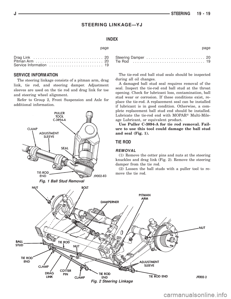
Use Puller C-3894-A for tie rod removal. Fail-
ure to use this tool could damage the ball stud
and seal (Fig. 1).
TIE ROD
REMOVAL
(1) Remove the cotter pins and nuts at the steering
knuckles and drag link (Fig. 2). Remove the steering
damper from the tie rod.
(2) Loosen the ball studs with a puller tool to re-
move the tie rod.
Fig. 1 Ball Stud Removal
Fig. 2 Steering Linkage
JSTEERING 19 - 19
Page 1558 of 2158
STEERING RHD
GENERAL SERVICE PROCEDURE INFORMATION
Right hand drive service procedures and torque
specifications involving steering; linkage, gear and
column are the same as left hand drive vehicles ex-
cept where shown. Refer to appropriate service pro-
cedures regarding each component in the system.
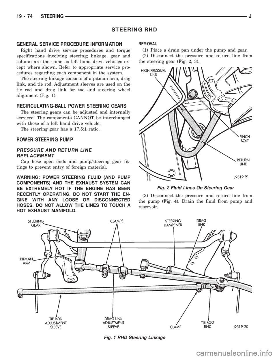
The steering linkage consists of a pitman arm, drag
link, and tie rod. Adjustment sleeves are used on the
tie rod and drag link for toe and steering wheel
alignment (Fig. 1).
RECIRCULATING-BALL POWER STEERING GEARS
The steering gears can be adjusted and internally
serviced. The components CANNOT be interchanged
with those of a left hand drive vehicle.
The steering gear has a 17.5:1 ratio.
POWER STEERING PUMP
PRESSURE AND RETURN LINE
REPLACEMENT
Cap hose open ends and pump/steering gear fit-
tings to prevent entry of foreign material.
WARNING: POWER STEERING FLUID (AND PUMP
COMPONENTS) AND THE EXHAUST SYSTEM CAN
BE EXTREMELY HOT IF THE ENGINE HAS BEEN
RECENTLY OPERATING. DO NOT START THE EN-
GINE WITH ANY LOOSE OR DISCONNECTED
HOSES. DO NOT ALLOW THE LINES TO TOUCH A
HOT EXHAUST MANIFOLD.REMOVAL
(1) Place a drain pan under the pump and gear.
(2) Disconnect the pressure and return line from
the steering gear (Fig. 2, 3).
(3) Disconnect the pressure and return line from
the pump (Fig. 4). Drain the fluid from pump and
reservoir.
Fig. 1 RHD Steering Linkage
Fig. 2 Fluid Lines On Steering Gear
19 - 74 STEERINGJ
Page 1635 of 2158
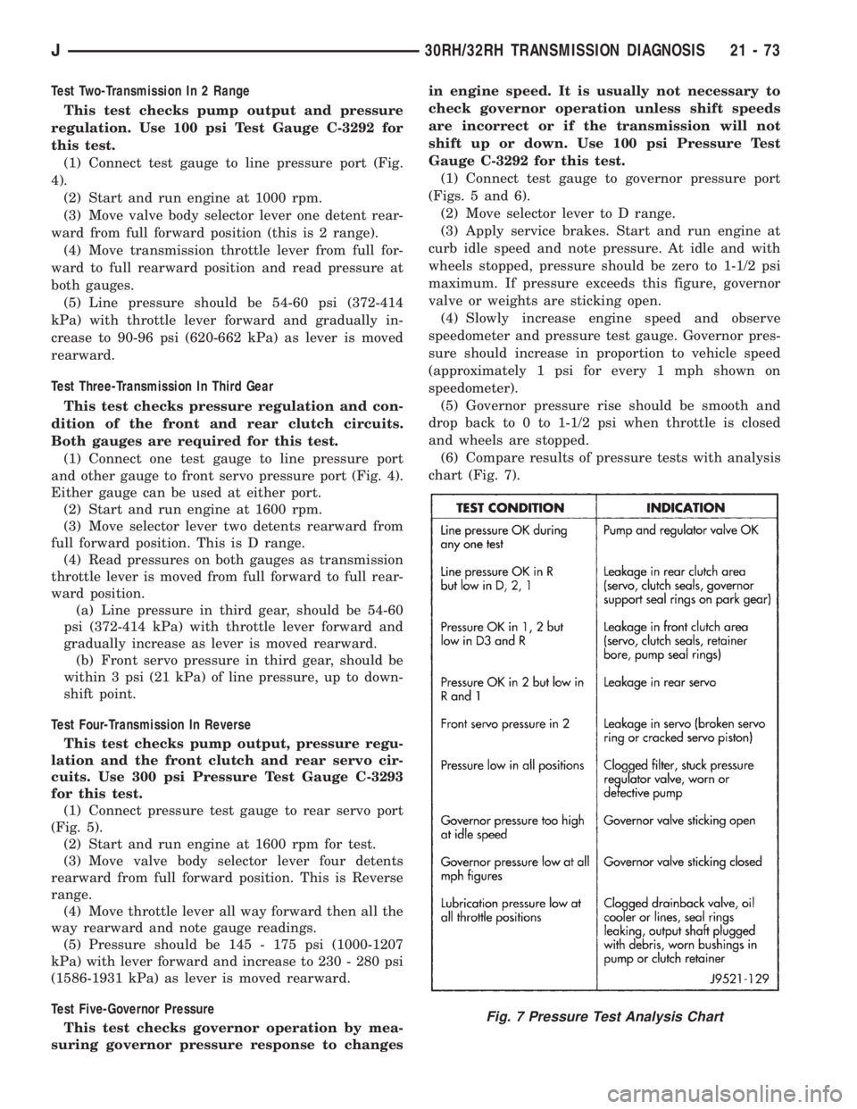
Test Two-Transmission In 2 Range
This test checks pump output and pressure
regulation. Use 100 psi Test Gauge C-3292 for
this test.
(1) Connect test gauge to line pressure port (Fig.
4).
(2) Start and run engine at 1000 rpm.
(3) Move valve body selector lever one detent rear-
ward from full forward position (this is 2 range).
(4) Move transmission throttle lever from full for-
ward to full rearward position and read pressure at
both gauges.
(5) Line pressure should be 54-60 psi (372-414
kPa) with throttle lever forward and gradually in-
crease to 90-96 psi (620-662 kPa) as lever is moved
rearward.
Test Three-Transmission In Third Gear
This test checks pressure regulation and con-
dition of the front and rear clutch circuits.
Both gauges are required for this test.
(1) Connect one test gauge to line pressure port
and other gauge to front servo pressure port (Fig. 4).
Either gauge can be used at either port.
(2) Start and run engine at 1600 rpm.
(3) Move selector lever two detents rearward from
full forward position. This is D range.
(4) Read pressures on both gauges as transmission
throttle lever is moved from full forward to full rear-
ward position.
(a) Line pressure in third gear, should be 54-60
psi (372-414 kPa) with throttle lever forward and
gradually increase as lever is moved rearward.
(b) Front servo pressure in third gear, should be
within 3 psi (21 kPa) of line pressure, up to down-
shift point.
Test Four-Transmission In Reverse
This test checks pump output, pressure regu-
lation and the front clutch and rear servo cir-
cuits. Use 300 psi Pressure Test Gauge C-3293
for this test.
(1) Connect pressure test gauge to rear servo port
(Fig. 5).
(2) Start and run engine at 1600 rpm for test.
(3) Move valve body selector lever four detents
rearward from full forward position. This is Reverse
range.
(4) Move throttle lever all way forward then all the
way rearward and note gauge readings.
(5) Pressure should be 145 - 175 psi (1000-1207
kPa) with lever forward and increase to 230 - 280 psi
(1586-1931 kPa) as lever is moved rearward.
Test Five-Governor Pressure
This test checks governor operation by mea-
suring governor pressure response to changesin engine speed. It is usually not necessary to
check governor operation unless shift speeds
are incorrect or if the transmission will not
shift up or down. Use 100 psi Pressure Test
Gauge C-3292 for this test.
(1) Connect test gauge to governor pressure port
(Figs. 5 and 6).
(2) Move selector lever to D range.
(3) Apply service brakes. Start and run engine at
curb idle speed and note pressure. At idle and with
wheels stopped, pressure should be zero to 1-1/2 psi
maximum. If pressure exceeds this figure, governor
valve or weights are sticking open.
(4) Slowly increase engine speed and observe
speedometer and pressure test gauge. Governor pres-
sure should increase in proportion to vehicle speed
(approximately 1 psi for every 1 mph shown on
speedometer).
(5) Governor pressure rise should be smooth and
drop back to 0 to 1-1/2 psi when throttle is closed
and wheels are stopped.
(6) Compare results of pressure tests with analysis
chart (Fig. 7).
Fig. 7 Pressure Test Analysis Chart
J30RH/32RH TRANSMISSION DIAGNOSIS 21 - 73
Page 1869 of 2158
NP242 TRANSFER CASE
INDEX
page page
General Information....................... 307
Operating Ranges........................ 307
Overhaul Cleaning and Inspection............ 318
Recommended Lubricant/Capacity/Fill Level..... 307
Shift Lever Installation (XJ)................. 309
Shift Lever Removal (XJ)................... 309
Shift Linkage Adjustment................... 309
Shift Mechanism......................... 307Speedometer Service..................... 309
Transfer Case Assembly................... 319
Transfer Case Changes.................... 307
Transfer Case Disassembly and Overhaul...... 310
Transfer Case Identification................. 307
Transfer Case Installation.................. 309
Transfer Case Removal.................... 309
GENERAL INFORMATION
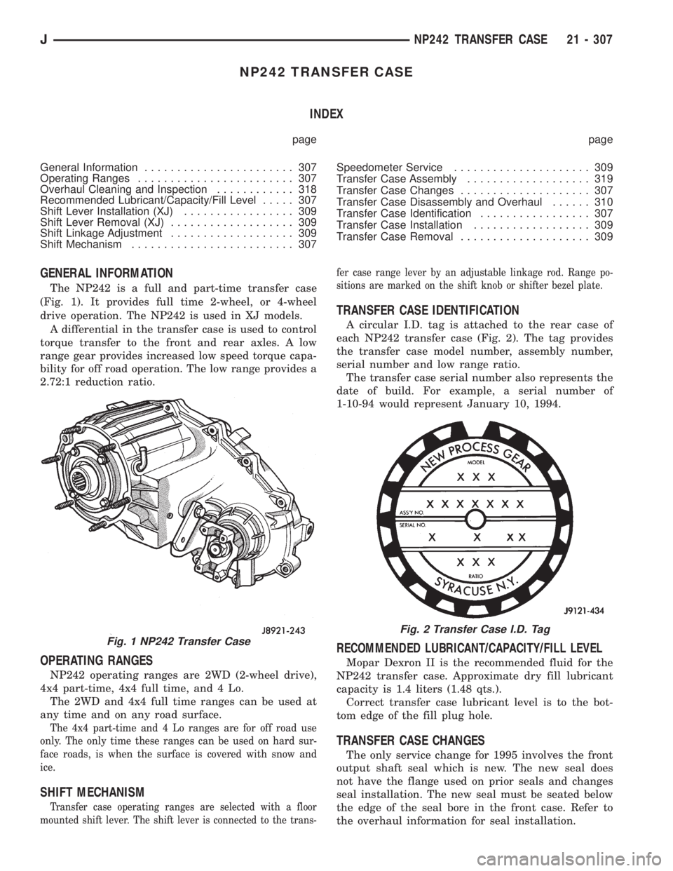
The NP242 is a full and part-time transfer case
(Fig. 1). It provides full time 2-wheel, or 4-wheel
drive operation. The NP242 is used in XJ models.
A differential in the transfer case is used to control
torque transfer to the front and rear axles. A low
range gear provides increased low speed torque capa-
bility for off road operation. The low range provides a
2.72:1 reduction ratio.
OPERATING RANGES
NP242 operating ranges are 2WD (2-wheel drive),
4x4 part-time, 4x4 full time, and 4 Lo.
The 2WD and 4x4 full time ranges can be used at
any time and on any road surface.
The 4x4 part-time and 4 Lo ranges are for off road use
only. The only time these ranges can be used on hard sur-
face roads, is when the surface is covered with snow and
ice.
SHIFT MECHANISM
Transfer case operating ranges are selected with a floor
mounted shift lever. The shift lever is connected to the trans-fer case range lever by an adjustable linkage rod. Range po-
sitions are marked on the shift knob or shifter bezel plate.
TRANSFER CASE IDENTIFICATION
A circular I.D. tag is attached to the rear case of
each NP242 transfer case (Fig. 2). The tag provides
the transfer case model number, assembly number,
serial number and low range ratio.
The transfer case serial number also represents the
date of build. For example, a serial number of
1-10-94 would represent January 10, 1994.
RECOMMENDED LUBRICANT/CAPACITY/FILL LEVEL
Mopar Dexron II is the recommended fluid for the
NP242 transfer case. Approximate dry fill lubricant
capacity is 1.4 liters (1.48 qts.).
Correct transfer case lubricant level is to the bot-
tom edge of the fill plug hole.
TRANSFER CASE CHANGES
The only service change for 1995 involves the front
output shaft seal which is new. The new seal does
not have the flange used on prior seals and changes
seal installation. The new seal must be seated below
the edge of the seal bore in the front case. Refer to
the overhaul information for seal installation.
Fig. 1 NP242 Transfer Case
Fig. 2 Transfer Case I.D. Tag
JNP242 TRANSFER CASE 21 - 307
Page 1910 of 2158
TIRE NOISE OR VIBRATION
The radial-ply tire on your vehicle is more sensitive
to improper mounting, or imbalance.
To determine if tires are the cause of vibration,
drive the vehicle over a smooth road at different
speeds. Note the effect of acceleration and decelera-
tion on noise level. Differential and exhaust noise
will change in intensity as speed varies. Tire noise
will usually remain constant.
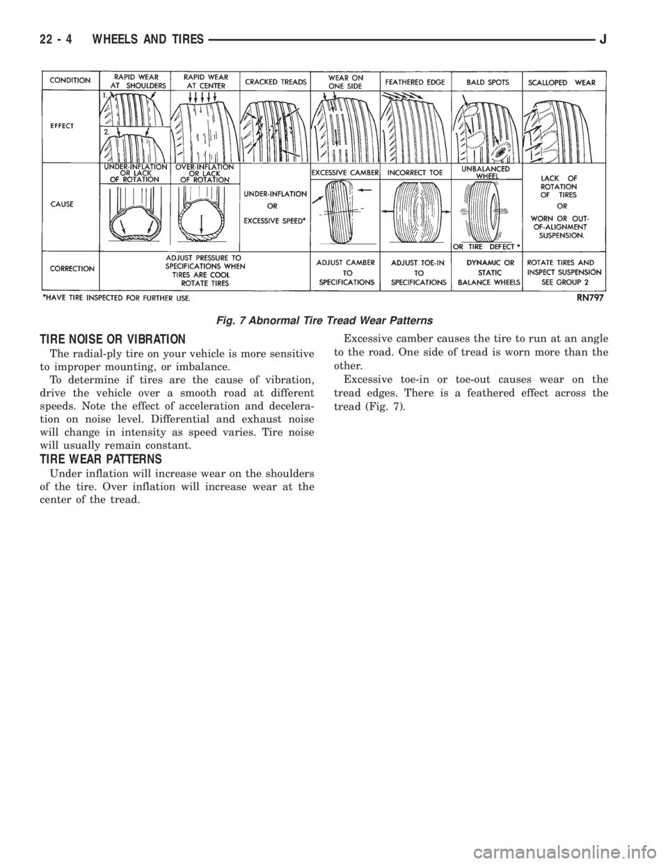
TIRE WEAR PATTERNS
Under inflation will increase wear on the shoulders
of the tire. Over inflation will increase wear at the
center of the tread.Excessive camber causes the tire to run at an angle
to the road. One side of tread is worn more than the
other.
Excessive toe-in or toe-out causes wear on the
tread edges. There is a feathered effect across the
tread (Fig. 7).
Fig. 7 Abnormal Tire Tread Wear Patterns
22 - 4 WHEELS AND TIRESJ
Page 1916 of 2158
VEHICLE VIBRATION
Vehicle vibration can be caused by:
²Tire/wheel unbalance or excessive runout
²Defective tires with extreme tread wear
²Nylon overlay flat spots (performance tires only)
²Incorrect wheel bearing adjustment (if applicable)
²Loose or worn suspension/steering components
²Certain tire tread patterns
²Incorrect drive shaft angles or excessive drive
shaft/yoke runout
²Defective or worn U-joints
²Excessive brake rotor or drum runout
²Loose engine or transmission supports/mounts
²And by engine operated accessories
Refer to the appropriate Groups in this man-
ual for additional information.
VIBRATION TYPES
There are two types of vehicle vibration:
²Mechanical
²Audible.
Mechanical vehicle vibration can be felt through
the seats, floor pan and/or steering wheel.
Audible vehicle vibration is heard above normal
background noise. The sound can be a droning or
drumming noise.
Vibrations are sensitive to change in engine torque,
vehicle speed or engine speed.
ENGINE TORQUE SENSITIVE VIBRATION
This vibration can be increased or decreased by:
²Accelerating
²Decelerating
²Coasting
²Maintaining a constant vehicle speed
VEHICLE SPEED SENSITIVE VIBRATION
This vibration condition always occurs at the same
vehicle speed regardless of the engine torque or en-
gine speed.
ENGINE SPEED (RPM) SENSITIVE VIBRATION
This vibration occurs at varying engine speeds. It
can be isolated by increasing or decreasing the en-
gine speed with the transmission in NEUTRAL posi-
tion.
VIBRATION DIAGNOSIS
A vibration diagnosis should always begin with a
10 mile (16 km) trip (to warm the vehicle and tires).
Then a road test to identify the vibration. Corrective
action should not be attempted until the vibration
type has been identified via a road test.
During the road test, drive the vehicle on a smooth
surface. If vibration exists, note and record the fol-
lowing information:²Identify the vehicle speed range when the vibra-
tion occurs
²Identify the type of vibration
²Identify the vibration sensitivity
²Determine if the vibration is affected by changes
in vehicle speed, engine speed and engine torque.
When the vibration has been identified, refer to the
Vibration Diagnosis chart for causes. Consider cor-
recting only those causes coded in the chart that are
related to the vibration condition.
Refer to the following cause codes and descriptions
for explanations when referring to the chart.
TRRÐTire and Wheel Radial Runout:Vehicle
speed sensitive, mechanical vibration. The runout
will not cause vibration below 20 mph (32 km/h).
WHÐWheel Hop:Vehicle speed sensitive, me-
chanical vibration. The wheel hop generates rapid
up-down movement in the steering wheel. The vibra-
tion is most noticeable in the 20 - 40 mph (32 - 64
km/h) range. The wheel hop will not cause vibration
below 20 mph (32 km/h). Wheel hop is caused by a
tire/wheel that has a radial runout of more than
0.045 of-an-inch (1.14 mm). If wheel runout is accept-
able and combined runout cannot be reduced by re-
positioning the tire on wheel, replace tire.
TBÐTire/Wheel Balance:Vehicle speed sensitive,
mechanical vibration. Static tire/wheel unbalance
will not cause vibration below 30 mph (46 km/h). Dy-
namic tire/wheel unbalance will not cause vibration
below 40 mph (64 km/h).
TLRÐTire/Wheel Lateral runout:Vehicle speed
sensitive, mechanical vibration. The runout will not
cause vibration below 50 - 55 mph (80 - 88 km/h). Ex-
cessive lateral runout will also cause front-end
shimmy.
TWÐTire Wear:Vehicle speed sensitive, audible
vibration. Abnormal tire wear causes small vibration
in the 30 - 55 mph (88 km/h) range. This will pro-
duce a whine noise at high speed. The whine will
change to a growl noise when the speed is reduced.
WÐTire Waddle:Vehicle speed sensitive, mechan-
ical vibration. Irregular tire uniformity can cause
side-to-side motion during speeds up to 15 mph (24
km/h). If the motion is excessive, identify the defec-
tive tire and replace it.
UAJÐUniversal Joint (Drive Shaft) Angles:
Torque/vehicle speed sensitive, mechanical/audible vi-
bration. Incorrect drive shaft angles cause mechani-
cal vibration below 20 mph (32 km/h) and in the 70
mph (112 km/h) range. The incorrect angles can also
produce an audible vibration in the 20 - 50 mph (32 -
80 km/h) range. Caster adjustment could be required
to correct the angles.
UJÐUniversal Joints:Engine torque/vehicle
speed sensitive, mechanical/audible vibration. If the
22 - 10 WHEELS AND TIRESJ