1995 JEEP YJ power steering fluid
[x] Cancel search: power steering fluidPage 1497 of 2158
INSTALLATION
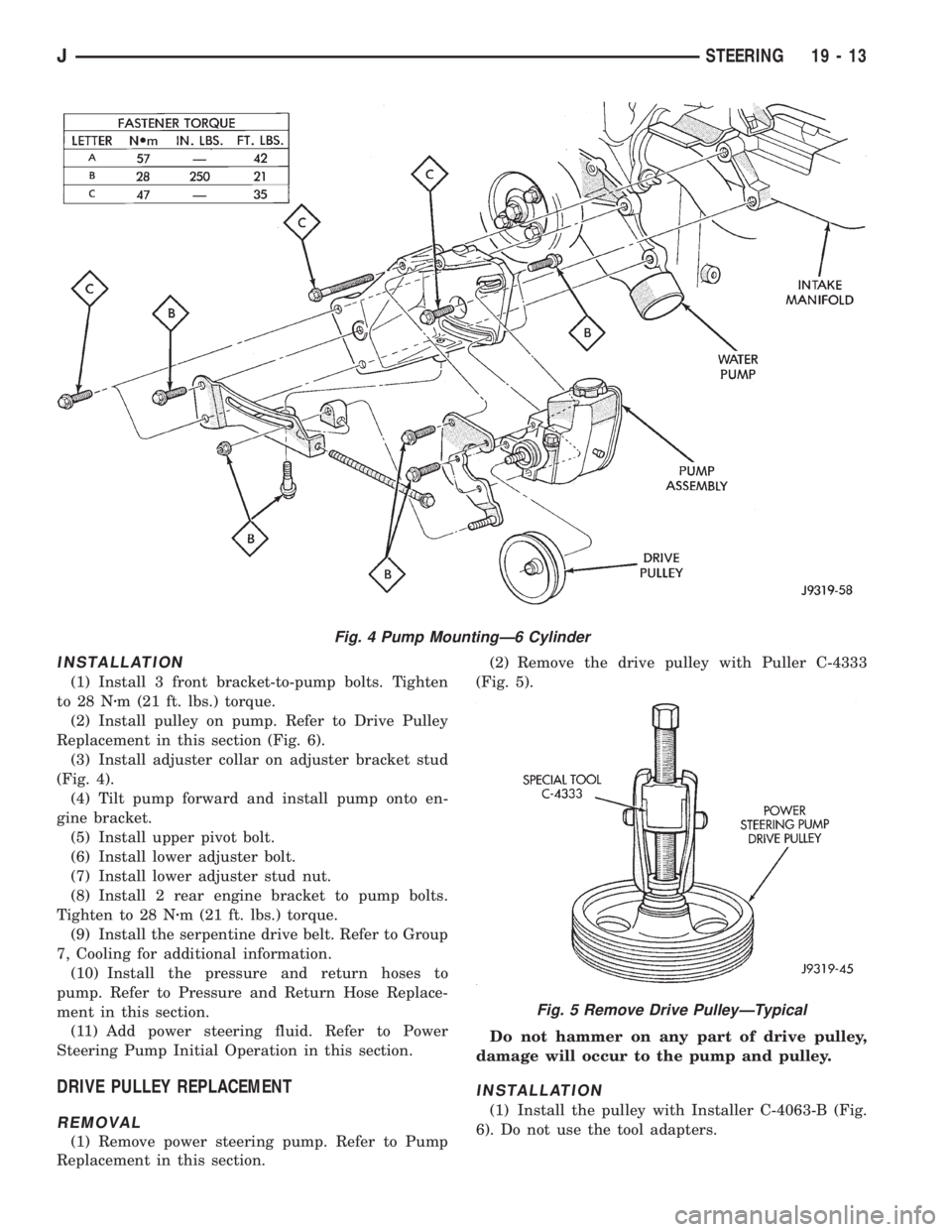
(1) Install 3 front bracket-to-pump bolts. Tighten
to 28 Nzm (21 ft. lbs.) torque.
(2) Install pulley on pump. Refer to Drive Pulley
Replacement in this section (Fig. 6).
(3) Install adjuster collar on adjuster bracket stud
(Fig. 4).
(4) Tilt pump forward and install pump onto en-
gine bracket.
(5) Install upper pivot bolt.
(6) Install lower adjuster bolt.
(7) Install lower adjuster stud nut.
(8) Install 2 rear engine bracket to pump bolts.
Tighten to 28 Nzm (21 ft. lbs.) torque.
(9) Install the serpentine drive belt. Refer to Group
7, Cooling for additional information.
(10) Install the pressure and return hoses to
pump. Refer to Pressure and Return Hose Replace-
ment in this section.
(11) Add power steering fluid. Refer to Power
Steering Pump Initial Operation in this section.
DRIVE PULLEY REPLACEMENT
REMOVAL
(1) Remove power steering pump. Refer to Pump
Replacement in this section.(2) Remove the drive pulley with Puller C-4333
(Fig. 5).
Do not hammer on any part of drive pulley,
damage will occur to the pump and pulley.
INSTALLATION
(1) Install the pulley with Installer C-4063-B (Fig.
6). Do not use the tool adapters.
Fig. 4 Pump MountingÐ6 Cylinder
Fig. 5 Remove Drive PulleyÐTypical
JSTEERING 19 - 13
Page 1498 of 2158
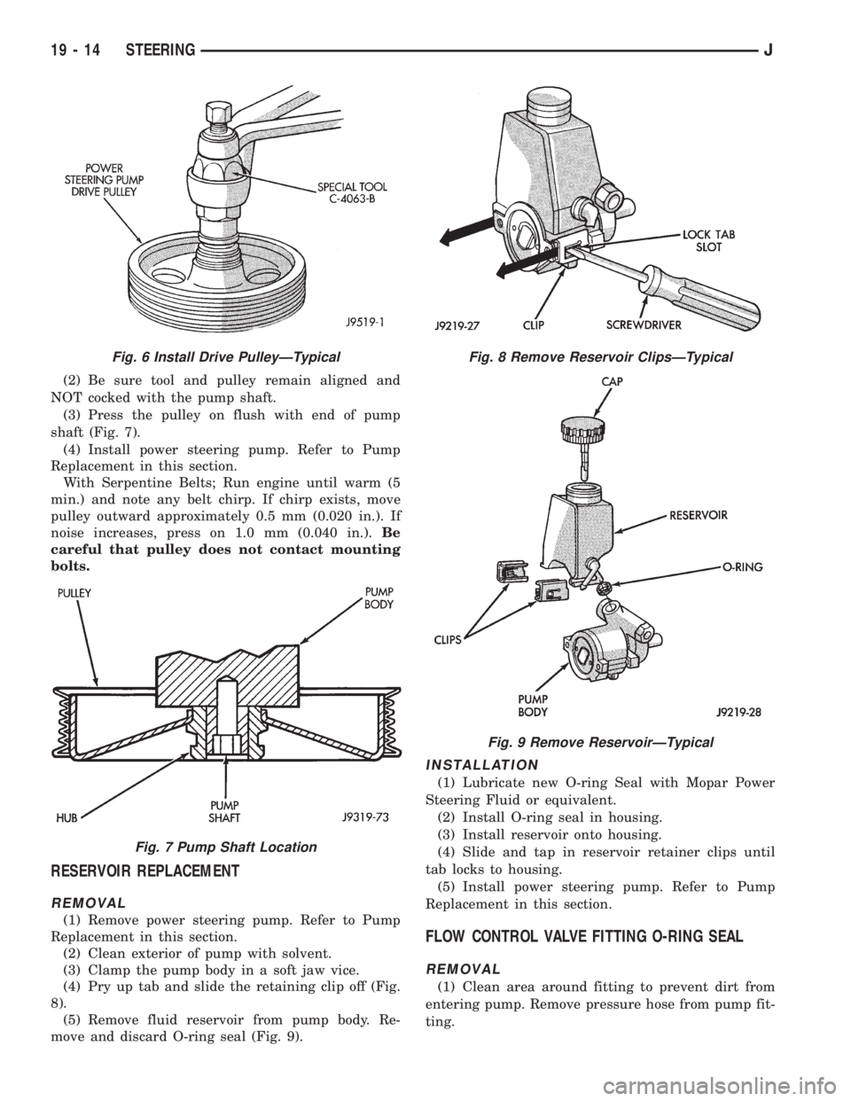
(2) Be sure tool and pulley remain aligned and
NOT cocked with the pump shaft.
(3) Press the pulley on flush with end of pump
shaft (Fig. 7).
(4) Install power steering pump. Refer to Pump
Replacement in this section.
With Serpentine Belts; Run engine until warm (5
min.) and note any belt chirp. If chirp exists, move
pulley outward approximately 0.5 mm (0.020 in.). If
noise increases, press on 1.0 mm (0.040 in.).Be
careful that pulley does not contact mounting
bolts.
RESERVOIR REPLACEMENT
REMOVAL
(1) Remove power steering pump. Refer to Pump
Replacement in this section.
(2) Clean exterior of pump with solvent.
(3) Clamp the pump body in a soft jaw vice.
(4) Pry up tab and slide the retaining clip off (Fig.
8).
(5) Remove fluid reservoir from pump body. Re-
move and discard O-ring seal (Fig. 9).
INSTALLATION
(1) Lubricate new O-ring Seal with Mopar Power
Steering Fluid or equivalent.
(2) Install O-ring seal in housing.
(3) Install reservoir onto housing.
(4) Slide and tap in reservoir retainer clips until
tab locks to housing.
(5) Install power steering pump. Refer to Pump
Replacement in this section.
FLOW CONTROL VALVE FITTING O-RING SEAL
REMOVAL
(1) Clean area around fitting to prevent dirt from
entering pump. Remove pressure hose from pump fit-
ting.
Fig. 6 Install Drive PulleyÐTypical
Fig. 7 Pump Shaft Location
Fig. 8 Remove Reservoir ClipsÐTypical
Fig. 9 Remove ReservoirÐTypical
19 - 14 STEERINGJ
Page 1499 of 2158
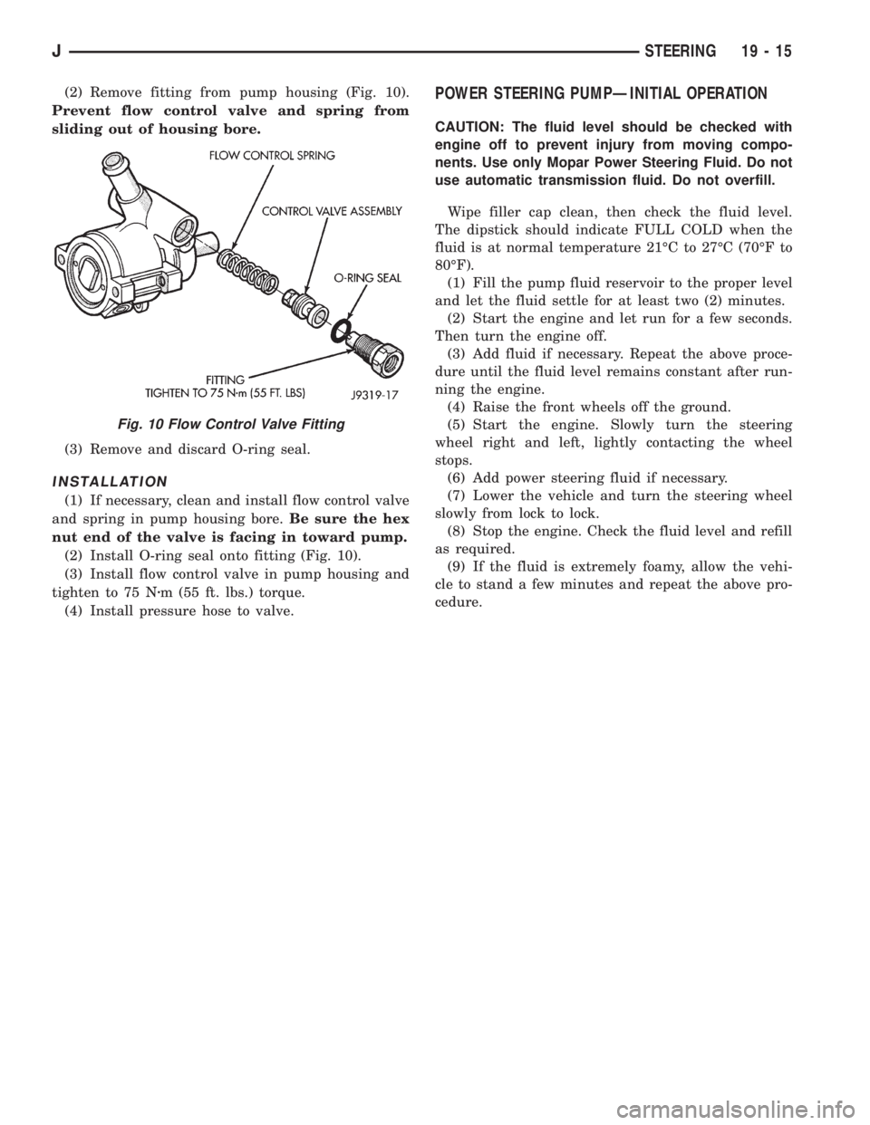
(2) Remove fitting from pump housing (Fig. 10).
Prevent flow control valve and spring from
sliding out of housing bore.
(3) Remove and discard O-ring seal.
INSTALLATION
(1) If necessary, clean and install flow control valve
and spring in pump housing bore.Be sure the hex
nut end of the valve is facing in toward pump.
(2) Install O-ring seal onto fitting (Fig. 10).
(3) Install flow control valve in pump housing and
tighten to 75 Nzm (55 ft. lbs.) torque.
(4) Install pressure hose to valve.
POWER STEERING PUMPÐINITIAL OPERATION
CAUTION: The fluid level should be checked with
engine off to prevent injury from moving compo-
nents. Use only Mopar Power Steering Fluid. Do not
use automatic transmission fluid. Do not overfill.
Wipe filler cap clean, then check the fluid level.
The dipstick should indicate FULL COLD when the
fluid is at normal temperature 21ÉC to 27ÉC (70ÉF to
80ÉF).
(1) Fill the pump fluid reservoir to the proper level
and let the fluid settle for at least two (2) minutes.
(2) Start the engine and let run for a few seconds.
Then turn the engine off.
(3) Add fluid if necessary. Repeat the above proce-
dure until the fluid level remains constant after run-
ning the engine.
(4) Raise the front wheels off the ground.
(5) Start the engine. Slowly turn the steering
wheel right and left, lightly contacting the wheel
stops.
(6) Add power steering fluid if necessary.
(7) Lower the vehicle and turn the steering wheel
slowly from lock to lock.
(8) Stop the engine. Check the fluid level and refill
as required.
(9) If the fluid is extremely foamy, allow the vehi-
cle to stand a few minutes and repeat the above pro-
cedure.
Fig. 10 Flow Control Valve Fitting
JSTEERING 19 - 15
Page 1507 of 2158
PITMAN SHAFT SEALSÐIN CAR REPLACEMENT
REMOVAL
(1) Remove pitman arm from gear. Refer to Pitman
Arm Removal in Steering Linkage.
(2) Clean exposed end of pitman shaft and hous-
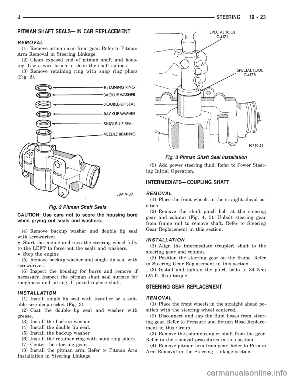
ing. Use a wire brush to clean the shaft splines.
(3) Remove retaining ring with snap ring pliers
(Fig. 2).
CAUTION: Use care not to score the housing bore
when prying out seals and washers.
(4) Remove backup washer and double lip seal
with screwdriver.
²Start the engine and turn the steering wheel fully
to the LEFT to force out the seals and washers.
²Stop the engine
(5) Remove backup washer and single lip seal with
screwdriver.
(6) Inspect the housing for burrs and remove if
necessary. Inspect the pitman shaft seal surface for
roughness and pitting. If pitted replace shaft.
INSTALLATION
(1) Install single lip seal with Installer or a suit-
able size deep socket (Fig. 3).
(2) Coat the double lip seal and washer with
grease.
(3) Install the backup washer.
(4) Install the double lip seal.
(5) Install the backup washer.
(6) Install the retainer ring with snap ring pliers.
(7) Center the steering gear.
(8) Install the pitman arm. Refer to Pitman Arm
Installation in Steering Linkage.(9) Add power steering fluid. Refer to Power Steer-
ing Initial Operation.
INTERMEDIATEÐCOUPLING SHAFT
REMOVAL
(1) Place the front wheels in the straight ahead po-
sition.
(2) Remove the shaft pinch bolt at the steering
gear and column (Fig. 4, 5). Unbolt steering gear
from frame rail to remove shaft. Refer to Steering
Gear Replacement in this section.
INSTALLATION
(1) Align the intermediate (coupler) shaft to the
steering gear and column.
(2) Position the steering gear on the frame. Refer
to Steering Gear Replacement in this section.
(3) Install and tighten the pinch bolts to 34 Nzm
(25 ft. lbs.) torque.
STEERING GEAR REPLACEMENT
REMOVAL
(1) Place the front wheels in the straight ahead po-
sition with the steering wheel centered.
(2) Disconnect and cap the fluid hoses from steer-
ing gear. Refer to Pressure and Return Hose Replace-
ment in this Group.
(3) Remove the column coupler shaft from the gear.
Refer to the removal procedures in this section.
(4) Remove pitman arm from gear. Refer to Pitman
Arm Removal in the Steering Linkage section.
Fig. 2 Pitman Shaft Seals
Fig. 3 Pitman Shaft Seal Installation
JSTEERING 19 - 23
Page 1508 of 2158
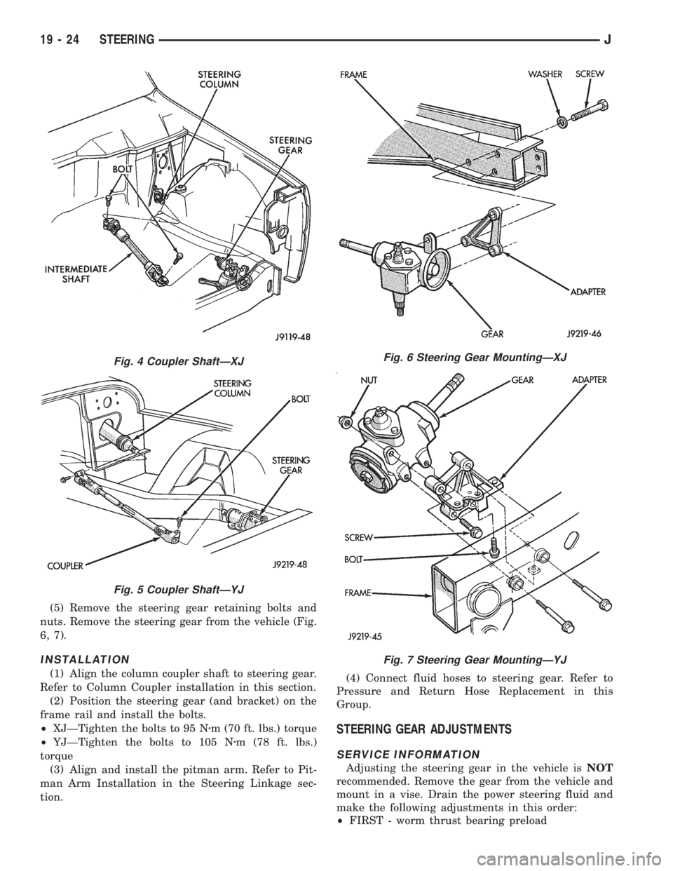
(5) Remove the steering gear retaining bolts and
nuts. Remove the steering gear from the vehicle (Fig.
6, 7).
INSTALLATION
(1) Align the column coupler shaft to steering gear.
Refer to Column Coupler installation in this section.
(2) Position the steering gear (and bracket) on the
frame rail and install the bolts.
²XJÐTighten the bolts to 95 Nzm (70 ft. lbs.) torque
²YJÐTighten the bolts to 105 Nzm (78 ft. lbs.)
torque
(3) Align and install the pitman arm. Refer to Pit-
man Arm Installation in the Steering Linkage sec-
tion.(4) Connect fluid hoses to steering gear. Refer to
Pressure and Return Hose Replacement in this
Group.
STEERING GEAR ADJUSTMENTS
SERVICE INFORMATION
Adjusting the steering gear in the vehicle isNOT
recommended. Remove the gear from the vehicle and
mount in a vise. Drain the power steering fluid and
make the following adjustments in this order:
²FIRST - worm thrust bearing preload
Fig. 4 Coupler ShaftÐXJ
Fig. 5 Coupler ShaftÐYJ
Fig. 6 Steering Gear MountingÐXJ
Fig. 7 Steering Gear MountingÐYJ
19 - 24 STEERINGJ
Page 1510 of 2158
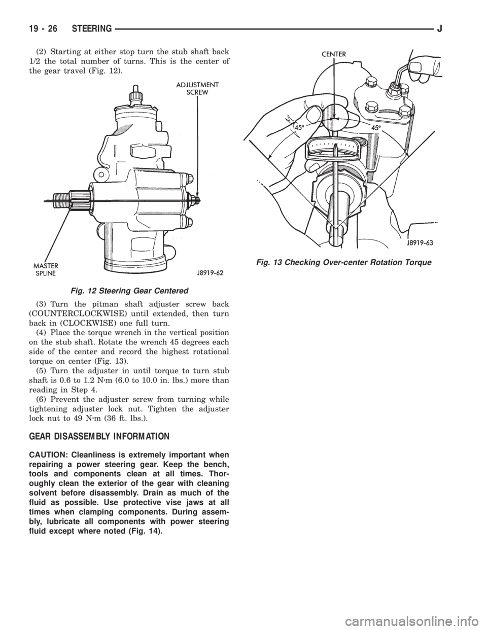
(2) Starting at either stop turn the stub shaft back
1/2 the total number of turns. This is the center of
the gear travel (Fig. 12).
(3) Turn the pitman shaft adjuster screw back
(COUNTERCLOCKWISE) until extended, then turn
back in (CLOCKWISE) one full turn.
(4) Place the torque wrench in the vertical position
on the stub shaft. Rotate the wrench 45 degrees each
side of the center and record the highest rotational
torque on center (Fig. 13).
(5) Turn the adjuster in until torque to turn stub
shaft is 0.6 to 1.2 Nzm (6.0 to 10.0 in. lbs.) more than
reading in Step 4.
(6) Prevent the adjuster screw from turning while
tightening adjuster lock nut. Tighten the adjuster
lock nut to 49 Nzm (36 ft. lbs.).
GEAR DISASSEMBLY INFORMATION
CAUTION: Cleanliness is extremely important when
repairing a power steering gear. Keep the bench,
tools and components clean at all times. Thor-
oughly clean the exterior of the gear with cleaning
solvent before disassembly. Drain as much of the
fluid as possible. Use protective vise jaws at all
times when clamping components. During assem-
bly, lubricate all components with power steering
fluid except where noted (Fig. 14).
Fig. 12 Steering Gear Centered
Fig. 13 Checking Over-center Rotation Torque
19 - 26 STEERINGJ
Page 1512 of 2158
PITMAN SHAFT AND SIDE COVER REPLACEMENT
REMOVE
(1) Remove steering gear from vehicle. Refer to
Power Steering Gear Replacement in this section.
(2) Remove pitman arm from steering gear. Refer
to Pitman Arm Removal in the Steering Linkage sec-
tion.
(3) Rotate stub shaft back and forth to drain power
steering fluid.
DISASSEMBLE
²Clean exposed end of pitman shaft and housing.
²Clean pitman shaft spline with a wire brush.
(1) Remove preload adjuster nut.
(2) Rotate stub shaft with socket to center gear.
Remove side cover bolts.
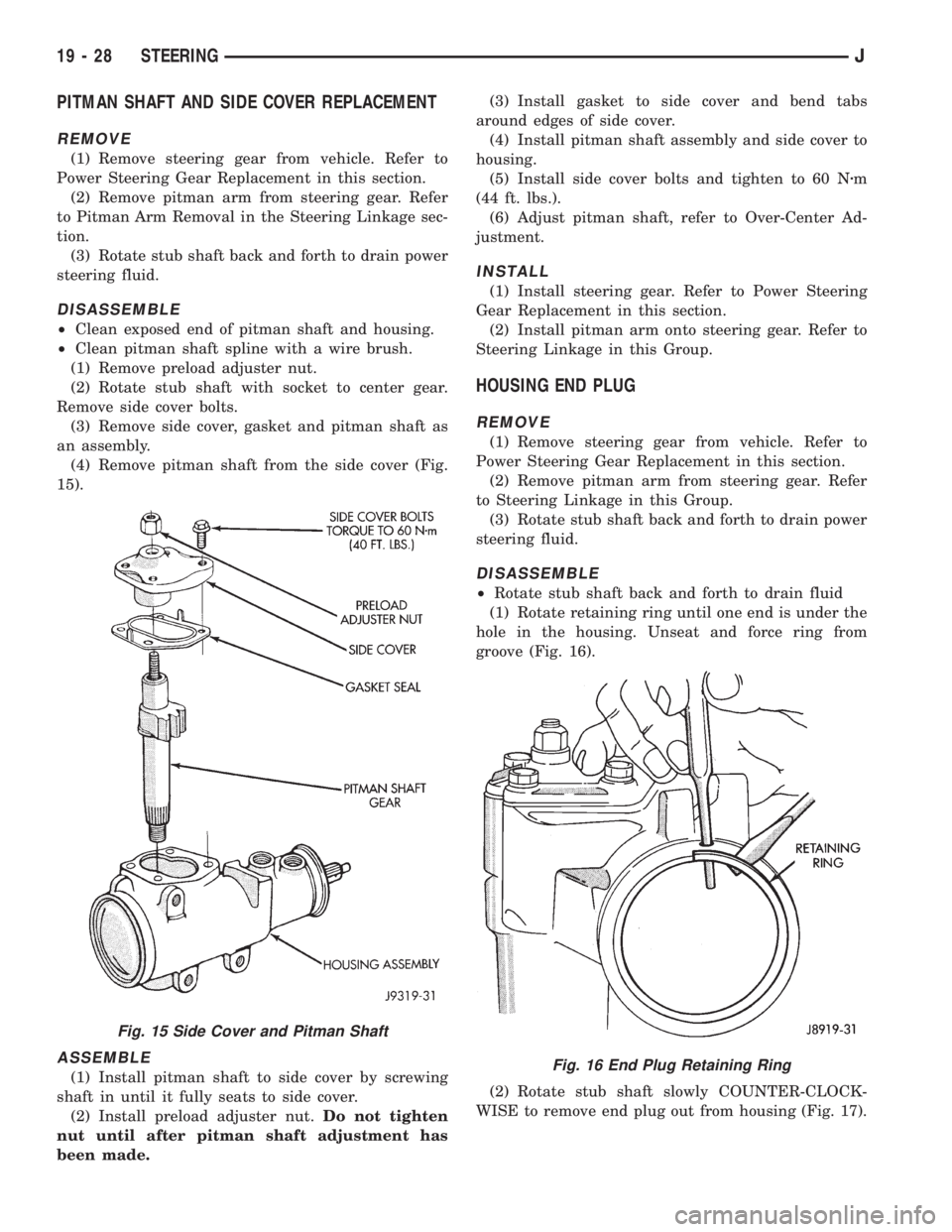
(3) Remove side cover, gasket and pitman shaft as
an assembly.
(4) Remove pitman shaft from the side cover (Fig.
15).
ASSEMBLE
(1) Install pitman shaft to side cover by screwing
shaft in until it fully seats to side cover.
(2) Install preload adjuster nut.Do not tighten
nut until after pitman shaft adjustment has
been made.(3) Install gasket to side cover and bend tabs
around edges of side cover.
(4) Install pitman shaft assembly and side cover to
housing.
(5) Install side cover bolts and tighten to 60 Nzm
(44 ft. lbs.).
(6) Adjust pitman shaft, refer to Over-Center Ad-
justment.
INSTALL
(1) Install steering gear. Refer to Power Steering
Gear Replacement in this section.
(2) Install pitman arm onto steering gear. Refer to
Steering Linkage in this Group.
HOUSING END PLUG
REMOVE
(1) Remove steering gear from vehicle. Refer to
Power Steering Gear Replacement in this section.
(2) Remove pitman arm from steering gear. Refer
to Steering Linkage in this Group.
(3) Rotate stub shaft back and forth to drain power
steering fluid.
DISASSEMBLE
²Rotate stub shaft back and forth to drain fluid
(1) Rotate retaining ring until one end is under the
hole in the housing. Unseat and force ring from
groove (Fig. 16).
(2) Rotate stub shaft slowly COUNTER-CLOCK-
WISE to remove end plug out from housing (Fig. 17).
Fig. 15 Side Cover and Pitman Shaft
Fig. 16 End Plug Retaining Ring
19 - 28 STEERINGJ
Page 1513 of 2158
CAUTION: Do not turn stub shaft any farther than
necessary. The recirculating balls will drop out of
the rack piston circuit and fall inside the rack pis-
ton chamber.
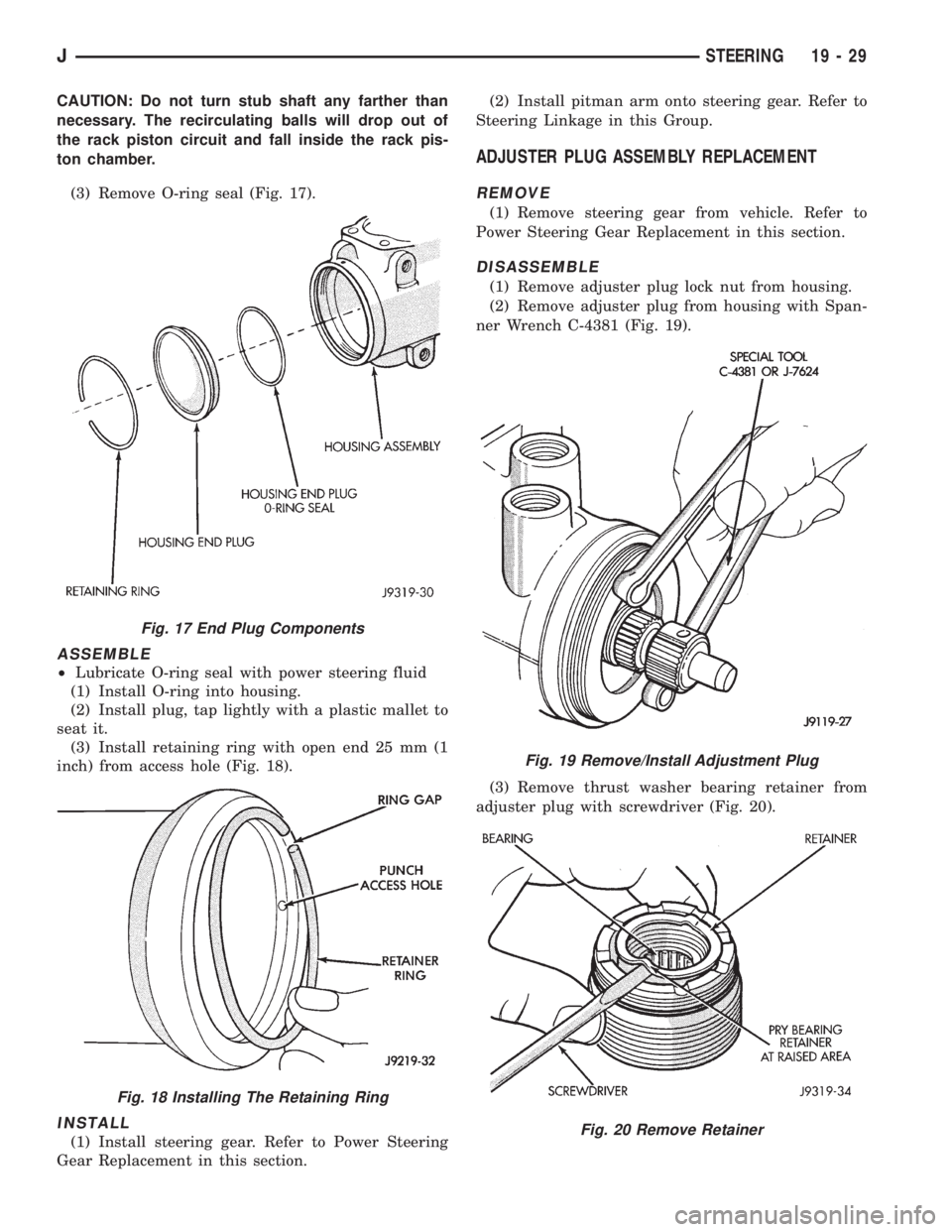
(3) Remove O-ring seal (Fig. 17).
ASSEMBLE
²Lubricate O-ring seal with power steering fluid
(1) Install O-ring into housing.
(2) Install plug, tap lightly with a plastic mallet to
seat it.
(3) Install retaining ring with open end 25 mm (1
inch) from access hole (Fig. 18).
INSTALL
(1) Install steering gear. Refer to Power Steering
Gear Replacement in this section.(2) Install pitman arm onto steering gear. Refer to
Steering Linkage in this Group.
ADJUSTER PLUG ASSEMBLY REPLACEMENT
REMOVE
(1) Remove steering gear from vehicle. Refer to
Power Steering Gear Replacement in this section.
DISASSEMBLE
(1) Remove adjuster plug lock nut from housing.
(2) Remove adjuster plug from housing with Span-
ner Wrench C-4381 (Fig. 19).
(3) Remove thrust washer bearing retainer from
adjuster plug with screwdriver (Fig. 20).
Fig. 17 End Plug Components
Fig. 18 Installing The Retaining Ring
Fig. 19 Remove/Install Adjustment Plug
Fig. 20 Remove Retainer
JSTEERING 19 - 29