1995 JEEP YJ power steering fluid
[x] Cancel search: power steering fluidPage 1340 of 2158
(29) Disconnect the exhaust pipe from the mani-
fold.
(30) Disconnect the engine speed sensor wire con-
nection.
(31) Remove the exhaust pipe support.
(32) Remove the flywheel and converter housing
access cover.
(33)Vehicles with Automatic Transmission:
(a) Mark the converter and drive plate location.
(b) Remove the converter-to-drive plate bolts.
(34) Remove the upper flywheel and converter
housing bolts and loosen the bottom bolts.
(35) Remove the engine mount cushion-to-engine
compartment bracket bolts.
(36) Lower the vehicle.
(37) Attach a lifting device to the engine.
(38) Raise the engine off the front supports.
(39) Place a support or floor jack under the con-
verter (or flywheel) housing.
(40) Remove the remaining converter (or flywheel)
housing bolts.
(41) Lift the engine out of the engine compart-
ment.
INSTALLATION
CAUTION: When installing the engine into a vehicle
equipped with an automatic transmission, be care-
ful not to damage the trigger wheel on the flywheel.
(1) Attach a lifting device to the engine and lower
the engine into the engine compartment. For easier
installation, it may be necessary to remove the en-
gine mount cushions from the engine mount bracket
as an aide in alignment of the engine to the trans-
mission.
(2)Vehicles with Manual Transmission:
(a) Insert the transmission shaft into the clutch
spline.
(b) Align the flywheel housing with the engine.(c) Install and tighten the flywheel housing lower
bolts finger tight.
(3)Vehicles with Automatic Transmission:
(a) Align the transmission torque converter hous-
ing with the engine.
(b) Loosely install the converter housing lower
bolts and install the next higher bolt and nut on
each side.
(c) Tighten all 4 bolts finger tight.
(4) Install the engine mount cushions (if removed).
(5) Lower the engine and engine mount cushions
onto the engine compartment brackets. Install the
bolts and finger tighten the nuts.
(6) Remove the engine lifting device.
(7) Raise and support the vehicle.
(8) Install the remaining flywheel and converter
housing bolts. Tighten all bolts to 38 Nzm (28 ft. lbs.)
torque.
(9)Vehicles with Automatic Transmission:
(a) Install the converter-to-drive plate bolts.
(b) Ensure the installation reference marks are
aligned.
(10) Install the flywheel and converter housing ac-
cess cover.
(11) Install the exhaust pipe support and tighten
the screw.
(12) Tighten the engine mount-to-bracket bolts.
(13) Connect the engine speed sensor wire connec-
tions and tighten the screws.
(14) Connect the exhaust pipe to the manifold.
(15) Install the starter motor and connect the ca-
ble.
(16) Connect the wires to the starter motor sole-
noid.
(17) Lower the vehicle.
(18) Connect all the vacuum hoses and wire con-
nectors identified during engine removal.
(19) If equipped with power steering:
(a) Remove the protective caps
(b) Connect the hoses to the fittings at the steer-
ing gear. Tighten the nut to 52 Nzm (38 ft. lbs.)
torque.
(c) Fill the pump reservoir with fluid.
(20) Install the power brake vacuum check valve to
the booster, if equipped.
(21) Connect the fuel inlet and return hoses at the
fuel rail. Verify that the quick-connect fitting assem-
bly fits securely over the fuel lines by giving the fuel
lines a firm tug.
(22) Install the fuel line bracket to the intake man-
ifold.
(23) Connect the distributor electrical connector
and oil pressure switch connector.
(24) Connect the injection system wire harness
connector on the dash panel.
(25) Connect the line pressure cable (if equipped
with automatic transmission).
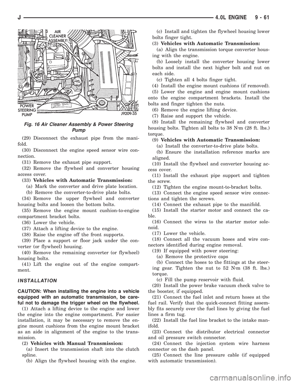
Fig. 16 Air Cleaner Assembly & Power Steering
Pump
J4.0L ENGINE 9 - 61
Page 1343 of 2158
(16) Remove the pulley-to-water pump flange
alignment capscrew and install the fan and spacer or
Tempatrol fan assembly.
(17) Tighten the serpentine drive belt according to
the specifications listed in Group 7, Cooling System.
(18) Install the fan shroud and radiator (refer to
Group 7, Cooling System for the proper procedure).
(19) Connect the radiator hoses.
(20) Connect the throttle valve rod and retainer.
(21) Connect the throttle cable and install the rod.
(22) Install the throttle valve rod spring.
(23) Connect the speed control cable, if equipped.
(24) Connect the oxygen sensor wire connector.
(25) Install the vacuum hose and check valve on
the brake booster.
(26) Connect the coolant temperature sensor wire
connector.
(27) Connect the idle speed actuator wire connec-
tor.
(28) Connect the fuel inlet and return hoses at the
fuel rail. Verify that the quick-connect fitting assem-
bly fits securely over the fuel lines by giving the fuel
lines a firm tug.
(29) Install the fuel line bracket to the intake man-
ifold.
(30) Connect all fuel injection wire connections.
(31) Install the engine ground strap.
(32) Connect the ignition coil wire connector.
(33) Remove the coolant temperature sending unit
to permit air to escape from the block. Fill the cool-
ing system with coolant. Install the coolant tempera-
ture sending unit when the system is filled.
(34) If equipped with power steering:
(a) Remove the protective caps
(b) Connect the hoses to the fittings at the steer-
ing gear. Tighten the nut to 52 Nzm (38 ft. lbs.)
torque.
(c) Fill the pump reservoir with fluid.
(35) Install the battery and connect the battery ca-
bles.
(36) Install the air cleaner bonnet to the throttle
body.
(37) Install the air cleaner.
(38) Lower the hood and secure in place.
(39) Start the engine and inspect for leaks.
(40) Stop the engine and check the fluid levels.
Add fluid, as required.
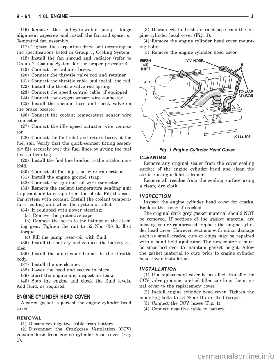
ENGINE CYLINDER HEAD COVER
A cured gasket is part of the engine cylinder head
cover.
REMOVAL
(1) Disconnect negative cable from battery.
(2) Disconnect the Crankcase Ventilation (CCV)
vacuum hose from engine cylinder head cover (Fig.
1).(3) Disconnect the fresh air inlet hose from the en-
gine cylinder head cover (Fig. 1).
(4) Remove the engine cylinder head cover mount-
ing bolts.
(5) Remove the engine cylinder head cover.
CLEANING
Remove any original sealer from the cover sealing
surface of the engine cylinder head and clean the
surface using a fabric cleaner.
Remove all residue from the sealing surface using
a clean, dry cloth.
INSPECTION
Inspect the engine cylinder head cover for cracks.
Replace the cover, if cracked.
The original dark grey gasket material should NOT
be removed. If sections of the gasket material are
missing or are compressed, replace the engine cylin-
der head cover. However, sections with minor damage
such as small cracks, cuts or chips may be repaired
with a hand held applicator. The new material must
be smoothed over to maintain gasket height. Allow
the gasket material to cure prior to engine cylinder
head cover installation.
INSTALLATION
(1) If a replacement cover is installed, transfer the
CCV valve grommet and oil filler cap from the origi-
nal cover to the replacement cover.
(2) Install engine cylinder head cover. Tighten the
mounting bolts to 13 Nzm (115 in. lbs.) torque.
(3) Connect the CCV hoses (Fig. 1).
(4) Connect negative cable to battery.
Fig. 1 Engine Cylinder Head Cover
9 - 64 4.0L ENGINEJ
Page 1466 of 2158
(2) Place a small container or shop towel beneath
the switch to collect any excess fluid.
(3) Remove the switch.
INSTALLATION
(1) Install the power steering switch.
(2) Connect the electrical connector to the switch.
(3) Check power steering fluid and add as neces-
sary.
(4) Start the engine and again check power steer-
ing fluid. Add fluid if necessary.
POWERTRAIN CONTROL MODULE (PCM)
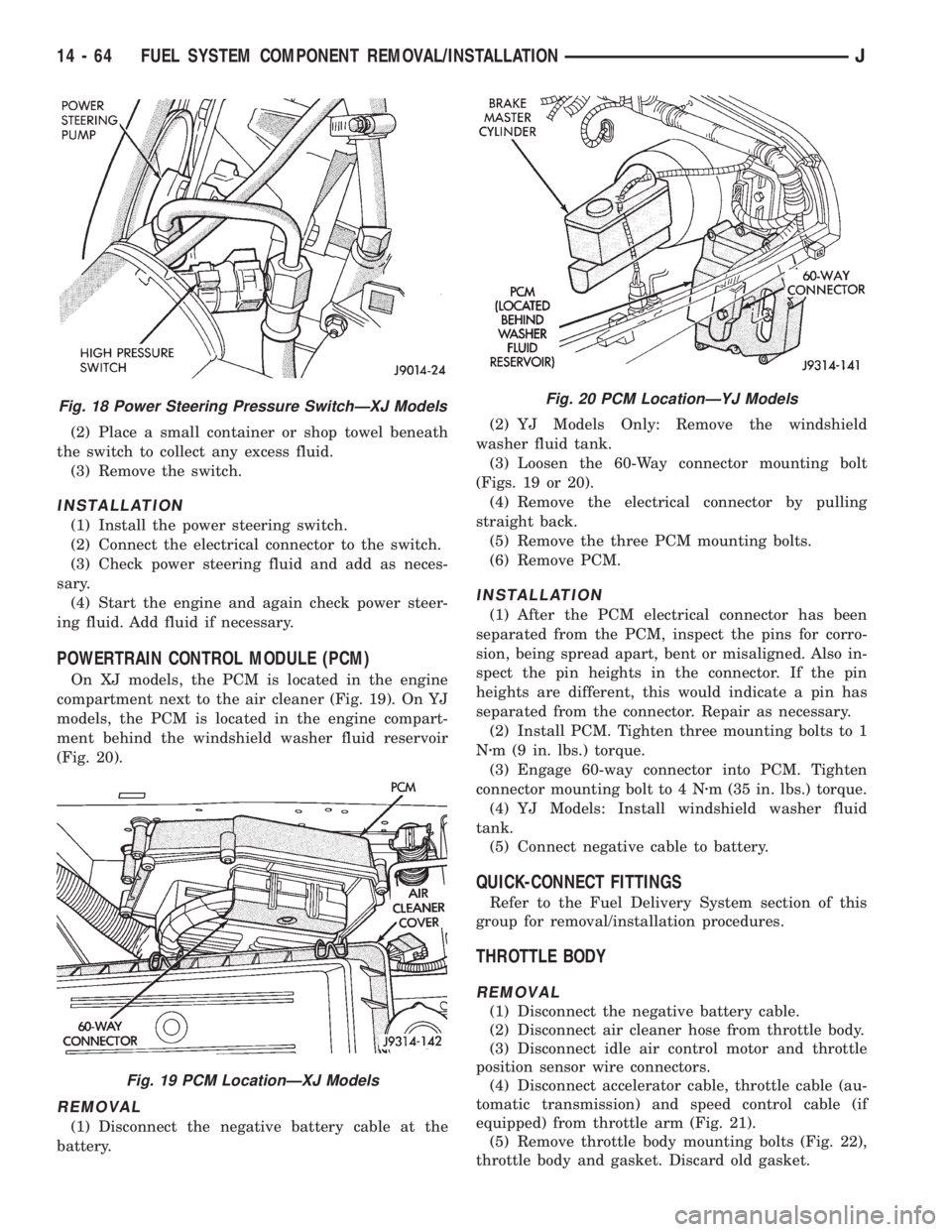
On XJ models, the PCM is located in the engine
compartment next to the air cleaner (Fig. 19). On YJ
models, the PCM is located in the engine compart-
ment behind the windshield washer fluid reservoir
(Fig. 20).
REMOVAL
(1) Disconnect the negative battery cable at the
battery.(2) YJ Models Only: Remove the windshield
washer fluid tank.
(3) Loosen the 60-Way connector mounting bolt
(Figs. 19 or 20).
(4) Remove the electrical connector by pulling
straight back.
(5) Remove the three PCM mounting bolts.
(6) Remove PCM.
INSTALLATION
(1) After the PCM electrical connector has been
separated from the PCM, inspect the pins for corro-
sion, being spread apart, bent or misaligned. Also in-
spect the pin heights in the connector. If the pin
heights are different, this would indicate a pin has
separated from the connector. Repair as necessary.
(2) Install PCM. Tighten three mounting bolts to 1
Nzm (9 in. lbs.) torque.
(3) Engage 60-way connector into PCM. Tighten
connector mounting bolt to 4 Nzm (35 in. lbs.) torque.
(4) YJ Models: Install windshield washer fluid
tank.
(5) Connect negative cable to battery.
QUICK-CONNECT FITTINGS
Refer to the Fuel Delivery System section of this
group for removal/installation procedures.
THROTTLE BODY
REMOVAL
(1) Disconnect the negative battery cable.
(2) Disconnect air cleaner hose from throttle body.
(3) Disconnect idle air control motor and throttle
position sensor wire connectors.
(4) Disconnect accelerator cable, throttle cable (au-
tomatic transmission) and speed control cable (if
equipped) from throttle arm (Fig. 21).
(5) Remove throttle body mounting bolts (Fig. 22),
throttle body and gasket. Discard old gasket.
Fig. 18 Power Steering Pressure SwitchÐXJ Models
Fig. 19 PCM LocationÐXJ Models
Fig. 20 PCM LocationÐYJ Models
14 - 64 FUEL SYSTEM COMPONENT REMOVAL/INSTALLATIONJ
Page 1485 of 2158
STEERING
CONTENTS
page page
GENERAL INFORMATION.................. 1
GENERAL INFORMATION................. 48
MANUAL STEERING GEAR................ 37
POWER STEERING PUMP................. 11
POWER STEERING SYSTEM DIAGNOSIS...... 3
RECIRCULATING BALL POWER STEERING
GEAR............................... 21STEERING COLUMN GENERAL SERVICEÐXJ . 47
STEERING COLUMNÐYJ................. 58
STEERING LINKAGEÐXJ................. 16
STEERING LINKAGEÐYJ................. 19
STEERING RHD......................... 74
TORQUE SPECIFICATIONS................ 78
GENERAL INFORMATION
STEERING SYSTEM COMPONENTS
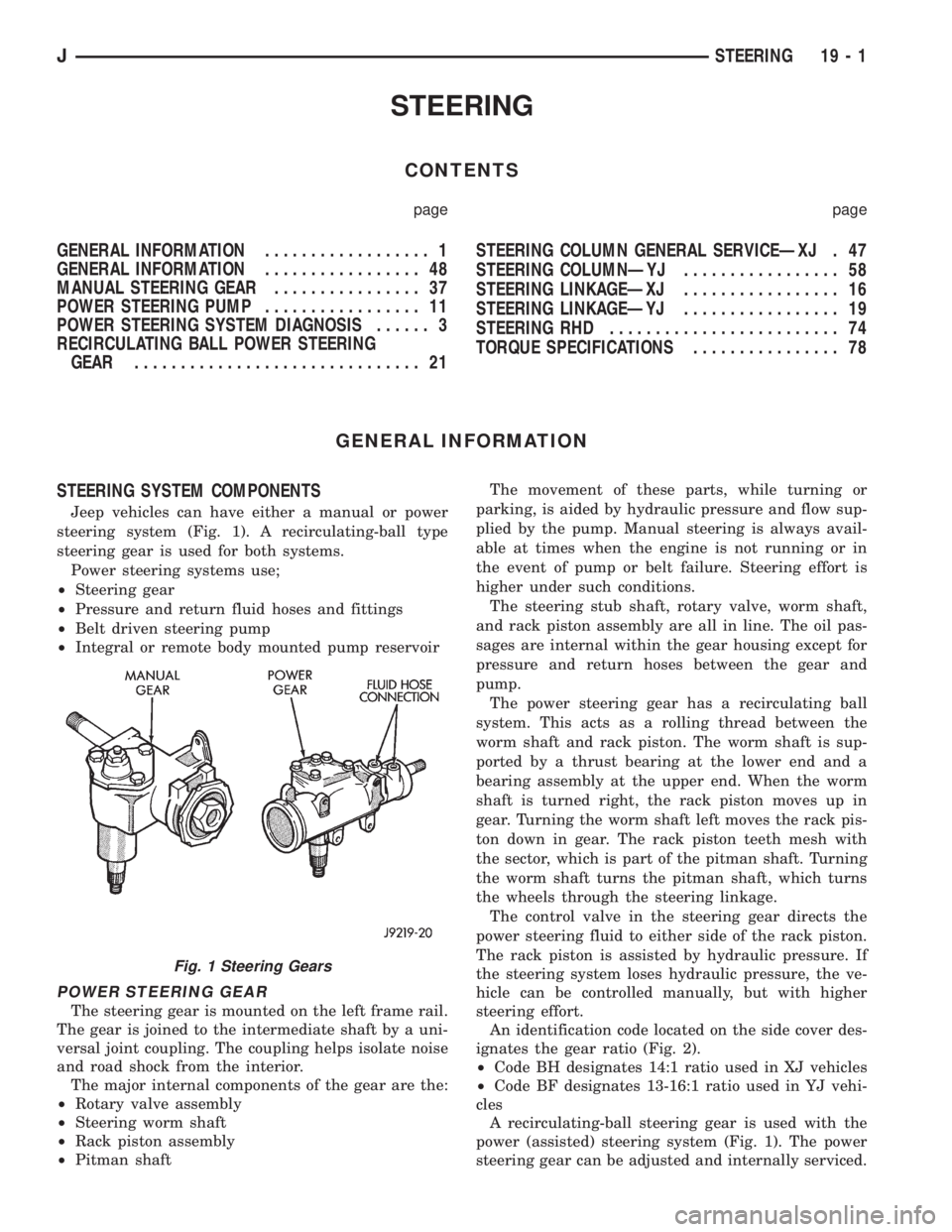
Jeep vehicles can have either a manual or power
steering system (Fig. 1). A recirculating-ball type
steering gear is used for both systems.
Power steering systems use;
²Steering gear
²Pressure and return fluid hoses and fittings
²Belt driven steering pump
²Integral or remote body mounted pump reservoir
POWER STEERING GEAR
The steering gear is mounted on the left frame rail.
The gear is joined to the intermediate shaft by a uni-
versal joint coupling. The coupling helps isolate noise
and road shock from the interior.
The major internal components of the gear are the:
²Rotary valve assembly
²Steering worm shaft
²Rack piston assembly
²Pitman shaftThe movement of these parts, while turning or
parking, is aided by hydraulic pressure and flow sup-
plied by the pump. Manual steering is always avail-
able at times when the engine is not running or in
the event of pump or belt failure. Steering effort is
higher under such conditions.
The steering stub shaft, rotary valve, worm shaft,
and rack piston assembly are all in line. The oil pas-
sages are internal within the gear housing except for
pressure and return hoses between the gear and
pump.
The power steering gear has a recirculating ball
system. This acts as a rolling thread between the
worm shaft and rack piston. The worm shaft is sup-
ported by a thrust bearing at the lower end and a
bearing assembly at the upper end. When the worm
shaft is turned right, the rack piston moves up in
gear. Turning the worm shaft left moves the rack pis-
ton down in gear. The rack piston teeth mesh with
the sector, which is part of the pitman shaft. Turning
the worm shaft turns the pitman shaft, which turns
the wheels through the steering linkage.
The control valve in the steering gear directs the
power steering fluid to either side of the rack piston.
The rack piston is assisted by hydraulic pressure. If
the steering system loses hydraulic pressure, the ve-
hicle can be controlled manually, but with higher
steering effort.
An identification code located on the side cover des-
ignates the gear ratio (Fig. 2).
²Code BH designates 14:1 ratio used in XJ vehicles
²Code BF designates 13-16:1 ratio used in YJ vehi-
cles
A recirculating-ball steering gear is used with the
power (assisted) steering system (Fig. 1). The power
steering gear can be adjusted and internally serviced.
Fig. 1 Steering Gears
JSTEERING 19 - 1
Page 1486 of 2158
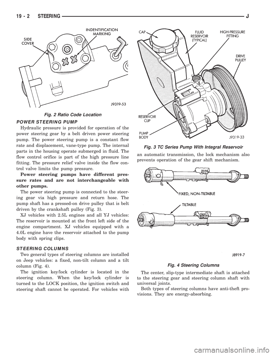
POWER STEERING PUMP
Hydraulic pressure is provided for operation of the
power steering gear by a belt driven power steering
pump. The power steering pump is a constant flow
rate and displacement, vane-type pump. The internal
parts in the housing operate submerged in fluid. The
flow control orifice is part of the high pressure line
fitting. The pressure relief valve inside the flow con-
trol valve limits the pump pressure.
Power steering pumps have different pres-
sure rates and are not interchangeable with
other pumps.
The power steering pump is connected to the steer-
ing gear via high pressure and return hose. The
pump shaft has a pressed-on drive pulley that is belt
driven by the crankshaft pulley (Fig. 3).
XJ vehicles with 2.5L engines and all YJ vehicles:
The reservoir is mounted at the front left side of the
engine compartment. XJ vehicles equipped with a
4.0L engine have the reservoir attached to the pump
body with spring clips.
STEERING COLUMNS
Two general types of steering columns are installed
on Jeep vehicles: a fixed, non-tilt column and a tilt
column (Fig. 4).
The ignition key/lock cylinder is located in the
steering column. When the key/lock cylinder is
turned to the LOCK position, the ignition switch and
steering shaft cannot be operated. For vehicles withan automatic transmission, the lock mechanism also
prevents operation of the gear shift mechanism.
The center, slip-type intermediate shaft is attached
to the steering gear and steering column shaft with
universal joints.
Both types of steering columns have anti-theft pro-
visions. They are energy-absorbing.
Fig. 2 Ratio Code Location
Fig. 3 TC Series Pump With Integral Reservoir
Fig. 4 Steering Columns
19 - 2 STEERINGJ
Page 1487 of 2158
POWER STEERING SYSTEM DIAGNOSIS
PUMP PRESSURE TEST
(1) Check belt tension and adjust as necessary.
(2) Disconnect high pressure hose at gear or pump.
Use a container for dripping fluid.
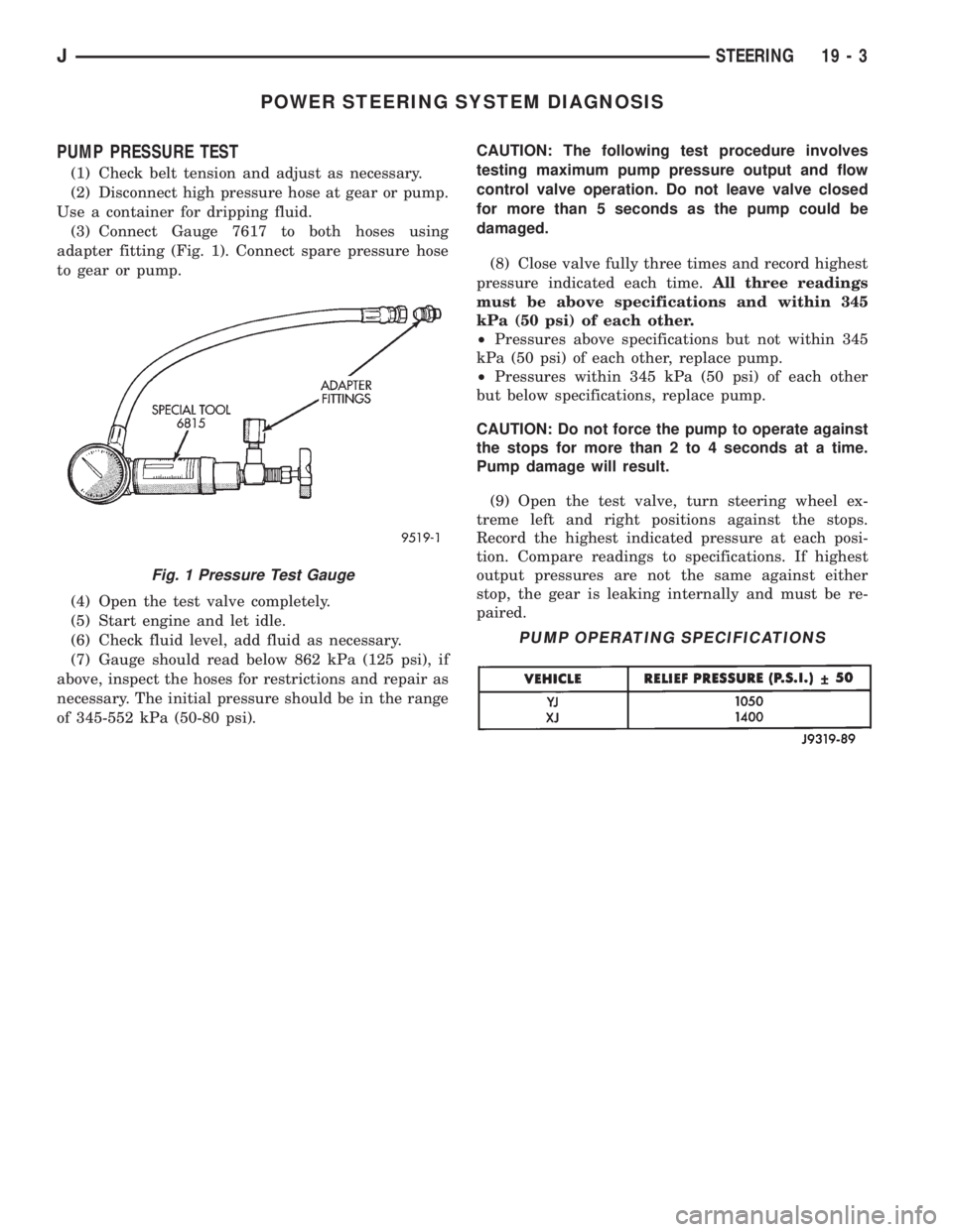
(3) Connect Gauge 7617 to both hoses using
adapter fitting (Fig. 1). Connect spare pressure hose
to gear or pump.
(4) Open the test valve completely.
(5) Start engine and let idle.
(6) Check fluid level, add fluid as necessary.
(7) Gauge should read below 862 kPa (125 psi), if
above, inspect the hoses for restrictions and repair as
necessary. The initial pressure should be in the range
of 345-552 kPa (50-80 psi).CAUTION: The following test procedure involves
testing maximum pump pressure output and flow
control valve operation. Do not leave valve closed
for more than 5 seconds as the pump could be
damaged.
(8) Close valve fully three times and record highest
pressure indicated each time.All three readings
must be above specifications and within 345
kPa (50 psi) of each other.
²Pressures above specifications but not within 345
kPa (50 psi) of each other, replace pump.
²Pressures within 345 kPa (50 psi) of each other
but below specifications, replace pump.
CAUTION: Do not force the pump to operate against
the stops for more than 2 to 4 seconds at a time.
Pump damage will result.
(9) Open the test valve, turn steering wheel ex-
treme left and right positions against the stops.
Record the highest indicated pressure at each posi-
tion. Compare readings to specifications. If highest
output pressures are not the same against either
stop, the gear is leaking internally and must be re-
paired.
Fig. 1 Pressure Test Gauge
PUMP OPERATING SPECIFICATIONS
JSTEERING 19 - 3
Page 1495 of 2158
POWER STEERING PUMP
INDEX
page page
Drive Pulley Replacement................... 13
Flow Control Valve Fitting O-Ring Seal......... 14
Power Steering PumpÐInitial Operation........ 15
Pressure and Return Hose Replacement........ 11Pump Replacement........................ 12
Reservoir Replacement..................... 14
Service Information........................ 11
SERVICE INFORMATION
The power steering pump internal components are
not serviced or adjusted. If a malfunction or an inter-
nal fluid leak occurs, the complete unit must be re-
placed. A reservoir, cap, and O-ring seal kit are the
only service components available.
PRESSURE AND RETURN HOSE REPLACEMENT
Cap hose open ends and pump/steering gear fit-
tings to prevent entry of foreign material.
WARNING: POWER STEERING FLUID (AND PUMP
COMPONENTS) AND THE EXHAUST SYSTEM CAN
BE EXTREMELY HOT IF THE ENGINE HAS BEEN
RECENTLY OPERATING. DO NOT START THE EN-
GINE WITH ANY LOOSE OR DISCONNECTED
HOSES. DO NOT ALLOW THE HOSES TO TOUCH A
HOT EXHAUST MANIFOLD OR THE CATALYTIC
CONVERTER.
REMOVAL
(1) Remove fasteners from hose retaining brackets
at all locations.
(2) If applicable, remove pressure sensor from
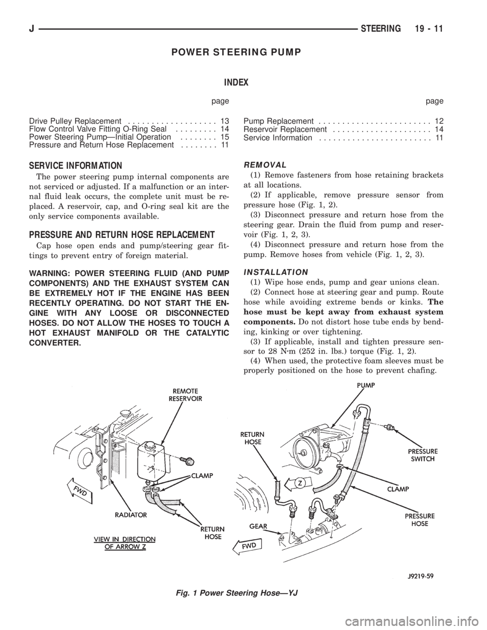
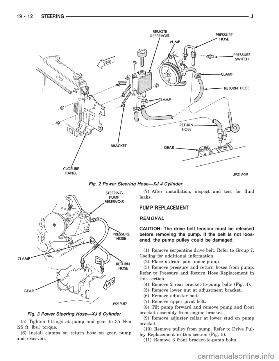
pressure hose (Fig. 1, 2).
(3) Disconnect pressure and return hose from the
steering gear. Drain the fluid from pump and reser-
voir (Fig. 1, 2, 3).
(4) Disconnect pressure and return hose from the
pump. Remove hoses from vehicle (Fig. 1, 2, 3).
INSTALLATION
(1) Wipe hose ends, pump and gear unions clean.
(2) Connect hose at steering gear and pump. Route
hose while avoiding extreme bends or kinks.The
hose must be kept away from exhaust system
components.Do not distort hose tube ends by bend-
ing, kinking or over tightening.
(3) If applicable, install and tighten pressure sen-
sor to 28 Nzm (252 in. lbs.) torque (Fig. 1, 2).
(4) When used, the protective foam sleeves must be
properly positioned on the hose to prevent chafing.
Fig. 1 Power Steering HoseÐYJ
JSTEERING 19 - 11
Page 1496 of 2158
(5) Tighten fittings at pump and gear to 35 Nzm
(25 ft. lbs.) torque.
(6) Install clamps on return hose on gear, pump
and reservoir.(7) After installation, inspect and test for fluid
leaks.
PUMP REPLACEMENT
REMOVAL
CAUTION: The drive belt tension must be released
before removing the pump. If the belt is not loos-
ened, the pump pulley could be damaged.
(1) Remove serpentine drive belt. Refer to Group 7,
Cooling for additional information.
(2) Place a drain pan under pump.
(3) Remove pressure and return hoses from pump.
Refer to Pressure and Return Hose Replacement in
this section.
(4) Remove 2 rear bracket-to-pump bolts (Fig. 4).
(5) Remove lower nut at adjustment bracket.
(6) Remove adjuster bolt.
(7) Remove upper pivot bolt.
(8) Tilt pump forward and remove pump and front
bracket assembly from engine bracket.
(9) Remove adjuster collar at lower stud on pump
bracket.
(10) Remove pulley from pump. Refer to Drive Pul-
ley Replacement in this section (Fig. 5).
(11) Remove 3 front bracket-to-pump bolts.
Fig. 2 Power Steering HoseÐXJ 4 Cylinder
Fig. 3 Power Steering HoseÐXJ 6 Cylinder
19 - 12 STEERINGJ