1995 JEEP YJ steering wheel adjustment
[x] Cancel search: steering wheel adjustmentPage 1500 of 2158
STEERING LINKAGEÐXJ
INDEX
page page
Drag Link............................... 16
Pitman Arm.............................. 17
Service Information........................ 16Steering Damper.......................... 17
TieRod ................................ 16
SERVICE INFORMATION
The steering linkage consists of a pitman arm, drag
link, tie rod, and steering damper. Adjustment
sleeves are used on the tie rod and drag link for toe
and steering wheel alignment.
Refer to Group 2, Front Suspension and Axle for
additional information.
The tie-rod end ball stud seals should be inspected
during all oil changes.
A damaged ball stud seal requires removal of the
seal. Inspect the tie-rod end ball stud at the throat
opening. Check for lubricant loss, contamination, ball
stud wear or corrosion. If these conditions exist, re-
place the tie-rod. A replacement seal can be installed
if lubricant is in good condition. Otherwise, a com-
plete replacement ball stud end should be installed.
Lubricate the tie-rod end with MOPARtMulti-Mile-
age Lubricant, or equivalent product.
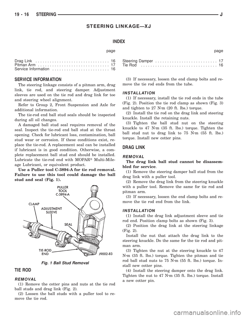
Use a Puller tool C-3894-A for tie rod removal.
Failure to use this tool could damage the ball
stud and seal (Fig. 1).
TIE ROD
REMOVAL
(1) Remove the cotter pins and nuts at the tie rod
ball studs and drag link (Fig. 2).
(2) Loosen the ball studs with a puller tool to re-
move the tie rod.(3) If necessary, loosen the end clamp bolts and re-
move the tie rod ends from the tube.
INSTALLATION
(1) If necessary, install the tie rod ends in the tube
(Fig. 2). Position the tie rod clamp as shown (Fig. 3)
and tighten to 27 Nzm (20 ft. lbs.) torque.
(2) Install the tie rod on the drag link and steering
knuckle. Install the retaining nuts.
(3) Tighten the ball stud nut on the steering
knuckle to 47 Nzm (35 ft. lbs.) torque. Tighten the
ball stud nut to drag link to 75 Nzm (55 ft. lbs.)
torque. Install new cotter pins.
DRAG LINK
REMOVAL
The drag link ball stud cannot be disassem-
bled for service.
(1) Remove the steering damper ball stud from the
drag link with a puller tool.
(2) Remove the drag link from the steering knuckle
with a puller tool. Remove the same for tie rod and
pitman arm.
(3) If necessary, loosen the end clamp bolts and re-
move the tie rod end from the link.
INSTALLATION
(1) Install the drag link adjustment sleeve and tie
rod end. Position clamp bolts as shown (Fig. 3).
(2) Position the drag link at the steering linkage
(Fig. 2).
Install the nut that attach the drag link to the
steering knuckle. Do the same for the tie rod and pit-
man arm.
(3) Tighten the nut at the steering knuckle to 47
Nzm (35 ft. lbs.) torque. Tighten the pitman and tie
rod ball stud nuts to 75 Nzm (55 ft. lbs.) torque. In-
stall new cotter pins.
(4) Install the steering damper onto the drag link.
Tighten the nut to 47 Nzm (35 ft. lbs.) torque. Install
a new cotter pin.
Fig. 1 Ball Stud Removal
19 - 16 STEERINGJ
Page 1503 of 2158
STEERING LINKAGEÐYJ
INDEX
page page
Drag Link............................... 20
Pitman Arm.............................. 20
Service Information........................ 19Steering Damper.......................... 20
TieRod ................................ 19
SERVICE INFORMATION
The steering linkage consists of a pitman arm, drag
link, tie rod, and steering damper. Adjustment
sleeves are used on the tie rod and drag link for toe
and steering wheel alignment.
Refer to Group 2, Front Suspension and Axle for
additional information.The tie-rod end ball stud seals should be inspected
during all oil changes.
A damaged ball stud seal requires removal of the
seal. Inspect the tie-rod end ball stud at the throat
opening. Check for lubricant loss, contamination, ball
stud wear or corrosion. If these conditions exist, re-
place the tie-rod. A replacement seal can be installed
if lubricant is in good condition. Otherwise, a com-
plete replacement ball stud end should be installed.
Lubricate the tie-rod end with MOPARtMulti-Mile-
age Lubricant, or equivalent product.
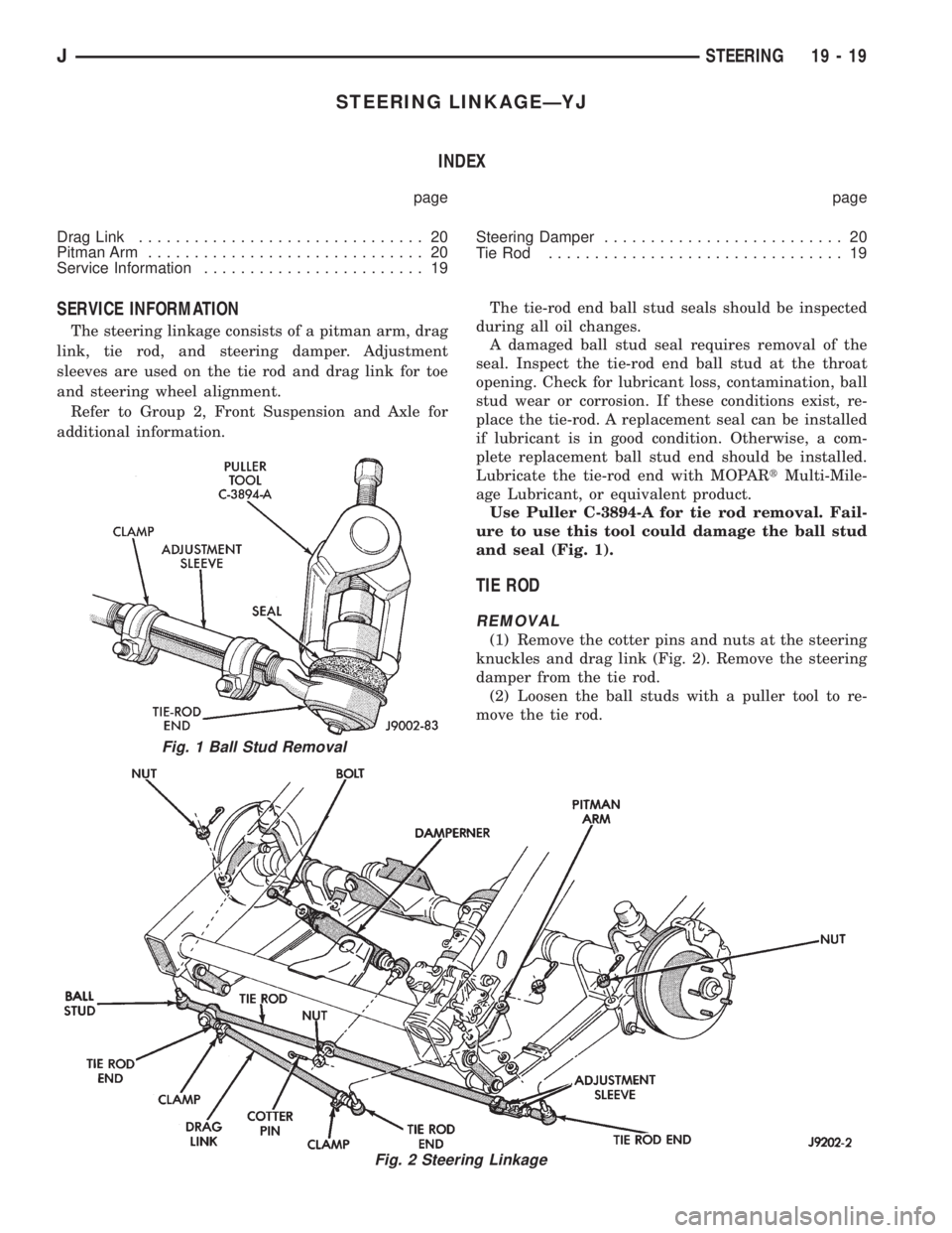
Use Puller C-3894-A for tie rod removal. Fail-
ure to use this tool could damage the ball stud
and seal (Fig. 1).
TIE ROD
REMOVAL
(1) Remove the cotter pins and nuts at the steering
knuckles and drag link (Fig. 2). Remove the steering
damper from the tie rod.
(2) Loosen the ball studs with a puller tool to re-
move the tie rod.
Fig. 1 Ball Stud Removal
Fig. 2 Steering Linkage
JSTEERING 19 - 19
Page 1504 of 2158
(3) If necessary, loosen the end clamp bolts and re-
move the tie rod end from the tube.
INSTALLATION
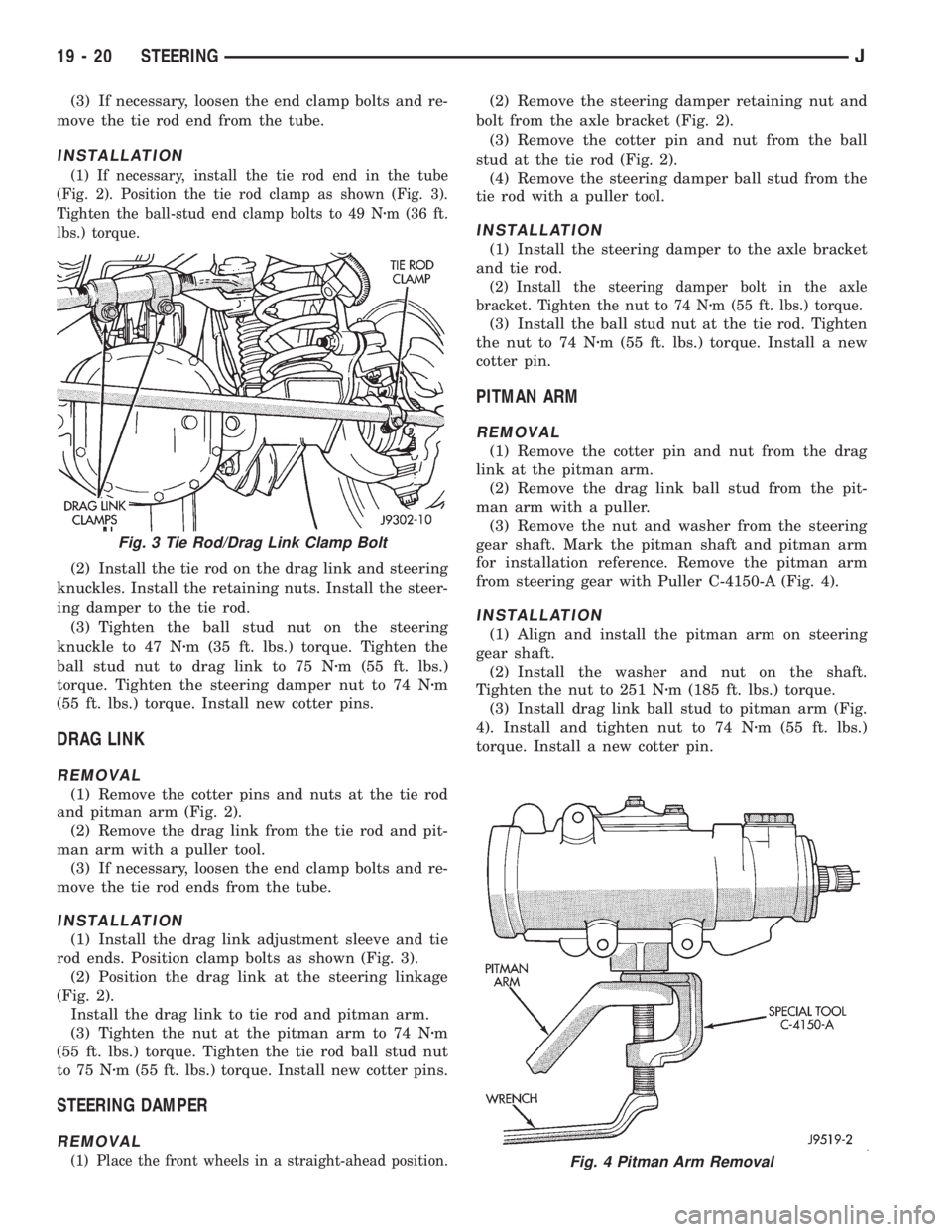
(1) If necessary, install the tie rod end in the tube
(Fig. 2). Position the tie rod clamp as shown (Fig. 3).
Tighten the ball-stud end clamp bolts to 49 Nzm (36 ft.
lbs.) torque.
(2) Install the tie rod on the drag link and steering
knuckles. Install the retaining nuts. Install the steer-
ing damper to the tie rod.
(3) Tighten the ball stud nut on the steering
knuckle to 47 Nzm (35 ft. lbs.) torque. Tighten the
ball stud nut to drag link to 75 Nzm (55 ft. lbs.)
torque. Tighten the steering damper nut to 74 Nzm
(55 ft. lbs.) torque. Install new cotter pins.
DRAG LINK
REMOVAL
(1) Remove the cotter pins and nuts at the tie rod
and pitman arm (Fig. 2).
(2) Remove the drag link from the tie rod and pit-
man arm with a puller tool.
(3) If necessary, loosen the end clamp bolts and re-
move the tie rod ends from the tube.
INSTALLATION
(1) Install the drag link adjustment sleeve and tie
rod ends. Position clamp bolts as shown (Fig. 3).
(2) Position the drag link at the steering linkage
(Fig. 2).
Install the drag link to tie rod and pitman arm.
(3) Tighten the nut at the pitman arm to 74 Nzm
(55 ft. lbs.) torque. Tighten the tie rod ball stud nut
to 75 Nzm (55 ft. lbs.) torque. Install new cotter pins.
STEERING DAMPER
REMOVAL
(1) Place the front wheels in a straight-ahead position.
(2) Remove the steering damper retaining nut and
bolt from the axle bracket (Fig. 2).
(3) Remove the cotter pin and nut from the ball
stud at the tie rod (Fig. 2).
(4) Remove the steering damper ball stud from the
tie rod with a puller tool.
INSTALLATION
(1) Install the steering damper to the axle bracket
and tie rod.
(2) Install the steering damper bolt in the axle
bracket. Tighten the nut to 74 Nzm (55 ft. lbs.) torque.
(3) Install the ball stud nut at the tie rod. Tighten
the nut to 74 Nzm (55 ft. lbs.) torque. Install a new
cotter pin.
PITMAN ARM
REMOVAL
(1) Remove the cotter pin and nut from the drag
link at the pitman arm.
(2) Remove the drag link ball stud from the pit-
man arm with a puller.
(3) Remove the nut and washer from the steering
gear shaft. Mark the pitman shaft and pitman arm
for installation reference. Remove the pitman arm
from steering gear with Puller C-4150-A (Fig. 4).
INSTALLATION
(1) Align and install the pitman arm on steering
gear shaft.
(2) Install the washer and nut on the shaft.
Tighten the nut to 251 Nzm (185 ft. lbs.) torque.
(3) Install drag link ball stud to pitman arm (Fig.
4). Install and tighten nut to 74 Nzm (55 ft. lbs.)
torque. Install a new cotter pin.
Fig. 4 Pitman Arm Removal
Fig. 3 Tie Rod/Drag Link Clamp Bolt
19 - 20 STEERINGJ
Page 1523 of 2158
(2) Wrap a single layer of plastic tape around the
pitman shaft threads and splines. This will protect
the replacement seals during installation.
(3) Install the seal with a suitable size socket.
(4) Remove the tape from the shaft.
(5) Center the steering gear.
(6) Align and install the pitman arm.
(7) Install the washer and retaining nut on the pit-
man shaft. Tighten the nut to 251 Nzm (185 ft. lbs.)
torque.
GEAR ADJUSTMENTS IN VEHICLE
REMOVE
(1) Raise and support the vehicle.
(2) Mark the pitman shaft and pitman arm for in-
stallation reference. Remove the pitman arm from
the shaft.
(3) Loosen the adjuster lock nut then back the ad-
juster plug off 1/4 turn.
(4) Remove the steering wheel horn pad.
(5) Turn the steering wheel in one direction until
stopped by the gear. Then turn back 1/2 turn.
CAUTION: Do not turn the steering wheel hard
against the internal stops when the linkage is re-
moved. This could result in damage to the recircu-
lating ball guides.
MEASURE
Place a low calibration (50 in. lbs.) torque wrench
and socket on the steering wheel nut. Rotate the
wrench and nut through a 90 degree arc (1/4 turn).
This will measure the worm shaft bearing preload.
ADJUST WORMSHAFT BEARING PRELOAD
TORQUE
(1) Adjust the preload by tightening the adjuster
plug. The preload should be 0.6 to 1 Nzm(5to8in.
lbs.) torque.
Steering column/shaft misalignment or damage will
increase the amount of torque required to rotate the
steering wheel. If the rotating torque is exceptionally
high, inspect the steering column/shaft alignment. If
the alignment is correct, remove the steering gear,
determine the cause of the high preload torque, and
repair as necessary.
(2) Tighten the adjuster locknut to 68 Nzm (50 ft.
lbs.) torque. Measure the preload torque. If neces-
sary, adjust the preload torque again.
ADJUST OVERCENTER DRAG TORQUE
(1) Turn the steering wheel from one stop to the
other and count the total numbers of turns. Turn the
wheel back in reverse direction 1/2 the total number
of turns to center the steering gear.(2) Turn the over center adjusting screw in to re-
move all lash between the ball nut and pitman shaft
sector teeth. Hold the adjustment screw and tighten
the lock nut to 34 Nzm (25 ft. lbs.) torque.
(3) Check the torque at the steering wheel by tak-
ing the highest reading as the wheel is turned
through the center position.
(4) The overcenter drag torque should be 0.5 to 1
Nzm (4 to 10 in. lbs.).
(5) If necessary, loosen the lock nut and adjust the
over center adjuster screw to obtain the proper
torque. Re-tighten the lock nut to the lock nut.
(6) After tightening the locknut, measure the over-
center drag torque again and readjust the torque, if
necessary.
INSTALL
(1) Align the installation reference marks and in-
stall the pitman arm.
(2) Install and tighten the pitman shaft nut and
washer to 251 Nzm (185 ft. lbs.) torque.
(3) Install the horn button.
GEAR DISASSEMBLY
(1) Rotate the wormshaft from stop-to-stop and
count the number of rotations. Rotate the wormshaft
in the reverse direction 1/2 of the total number of ro-
tations to center it and the ball nut.
(2) Remove the pitman shaft adjustment screw
locknut. Remove the cover retaining bolts, cover, and
gasket (Fig. 3).
(3) Slide the adjustment screw head (Fig. 3) out of
the pitman shaft T-slot and remove it and the
shim(s).
(4) Retain the shim(s) for end-play measurement
during assembly.
(5) Remove the pitman shaft, the wormshaft bear-
ing preload torque adjustment cap locknut, and the
adjustment cap (Fig. 2).
(6) Remove the wormshaft and the ball nut (Fig.
2).
(7) Remove (pry) the pitman shaft and the worm-
shaft seals from the steering gear housing (Fig. 3).
WORMSHAFT AND BALL NUT DISASSEMBLY
(1) Remove the upper bearing from the wormshaft
(Fig. 2).
CAUTION: Do not allow the ball nut to rotate freely
and travel to either extreme end of the wormshaft.
This could damage the tangs at the ends of the re-
circulating ball guides (Fig. 3).
(2) Remove the recirculating ball guide clamp re-
taining screws, the clamp and the guides (Fig. 2).
Separate the half-guides and place the recirculating
balls aside in a container.
JSTEERING 19 - 39
Page 1529 of 2158
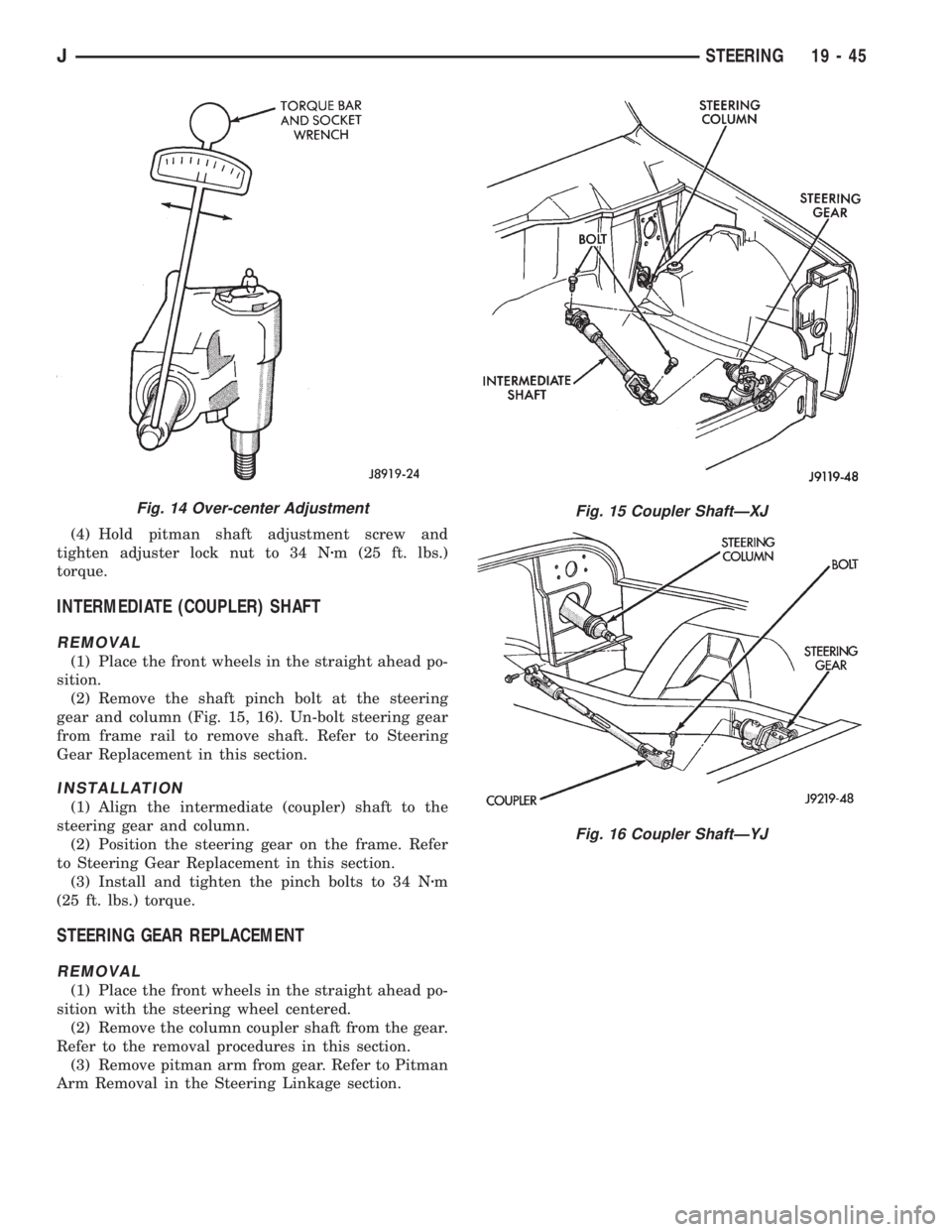
(4) Hold pitman shaft adjustment screw and
tighten adjuster lock nut to 34 Nzm (25 ft. lbs.)
torque.
INTERMEDIATE (COUPLER) SHAFT
REMOVAL
(1) Place the front wheels in the straight ahead po-
sition.
(2) Remove the shaft pinch bolt at the steering
gear and column (Fig. 15, 16). Un-bolt steering gear
from frame rail to remove shaft. Refer to Steering
Gear Replacement in this section.
INSTALLATION
(1) Align the intermediate (coupler) shaft to the
steering gear and column.
(2) Position the steering gear on the frame. Refer
to Steering Gear Replacement in this section.
(3) Install and tighten the pinch bolts to 34 Nzm
(25 ft. lbs.) torque.
STEERING GEAR REPLACEMENT
REMOVAL
(1) Place the front wheels in the straight ahead po-
sition with the steering wheel centered.
(2) Remove the column coupler shaft from the gear.
Refer to the removal procedures in this section.
(3) Remove pitman arm from gear. Refer to Pitman
Arm Removal in the Steering Linkage section.
Fig. 14 Over-center AdjustmentFig. 15 Coupler ShaftÐXJ
Fig. 16 Coupler ShaftÐYJ
JSTEERING 19 - 45
Page 1557 of 2158
(36) If equipped, install the cruise control wire har-
ness. Install the turn signal stalk by pushing it
straight into the column.
(37) Insert the hazard warning knob in the hazard
warning switch and press it inward. Align and install
the turn signal switch retaining screws. Ensure that
the turn signal switch is properly seated before tight-
ening the screws. Tighten the screws to 4 Nzm (33 in.
lbs.) torque. Thread the hazard warning switch knob
into the switch and pull the knob outward.
(38) Install and seat the upper bearing race in the
key/lock cylinder housing.
(39) Install the upper bearing preload spring, the
canceling cam and the lockplate.
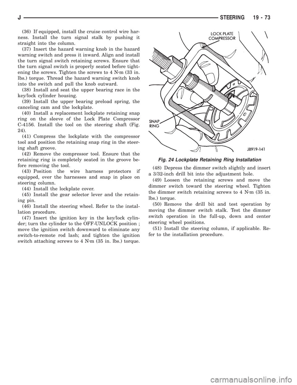
(40) Install a replacement lockplate retaining snap
ring on the sleeve of the Lock Plate Compressor
C-4156. Install the tool on the steering shaft (Fig.
24).
(41) Compress the lockplate with the compressor
tool and position the retaining snap ring in the steer-
ing shaft groove.
(42) Remove the compressor tool. Ensure that the
retaining ring is completely seated in the groove be-
fore removing the tool.
(43) Position the wire harness protectors if
equipped, over the harnesses and snap in place on
steering column.
(44) Install the lockplate cover.
(45) Install the gear selector lever and the retain-
ing pin.
(46) Install the steering wheel. Refer to the instal-
lation procedure.
(47) Insert the ignition key in the key/lock cylin-
der; turn the cylinder to the OFF-UNLOCK position ;
move the ignition switch downward to eliminate any
switch-to-remote rod lash; and tighten the ignition
switch attaching screws to 4 Nzm (35 in. lbs.) torque.(48) Depress the dimmer switch slightly and insert
a 3/32-inch drill bit into the adjustment hole.
(49) Loosen the retaining screws and move the
dimmer switch toward the steering wheel. Tighten
the dimmer switch retaining screws to 4 Nzm (35 in.
lbs.) torque.
(50) Remove the drill bit and test operation by
moving the dimmer switch stalk. Test the dimmer
switch operation in the full-up, down and center
steering wheel positions.
(51) Install the steering column, if applicable. Re-
fer to the installation procedure.
Fig. 24 Lockplate Retaining Ring Installation
JSTEERING 19 - 73
Page 1558 of 2158
STEERING RHD
GENERAL SERVICE PROCEDURE INFORMATION
Right hand drive service procedures and torque
specifications involving steering; linkage, gear and
column are the same as left hand drive vehicles ex-
cept where shown. Refer to appropriate service pro-
cedures regarding each component in the system.
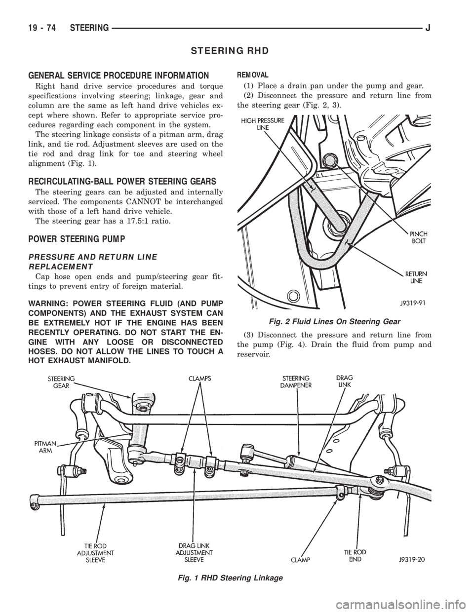
The steering linkage consists of a pitman arm, drag
link, and tie rod. Adjustment sleeves are used on the
tie rod and drag link for toe and steering wheel
alignment (Fig. 1).
RECIRCULATING-BALL POWER STEERING GEARS
The steering gears can be adjusted and internally
serviced. The components CANNOT be interchanged
with those of a left hand drive vehicle.
The steering gear has a 17.5:1 ratio.
POWER STEERING PUMP
PRESSURE AND RETURN LINE
REPLACEMENT
Cap hose open ends and pump/steering gear fit-
tings to prevent entry of foreign material.
WARNING: POWER STEERING FLUID (AND PUMP
COMPONENTS) AND THE EXHAUST SYSTEM CAN
BE EXTREMELY HOT IF THE ENGINE HAS BEEN
RECENTLY OPERATING. DO NOT START THE EN-
GINE WITH ANY LOOSE OR DISCONNECTED
HOSES. DO NOT ALLOW THE LINES TO TOUCH A
HOT EXHAUST MANIFOLD.REMOVAL
(1) Place a drain pan under the pump and gear.
(2) Disconnect the pressure and return line from
the steering gear (Fig. 2, 3).
(3) Disconnect the pressure and return line from
the pump (Fig. 4). Drain the fluid from pump and
reservoir.
Fig. 1 RHD Steering Linkage
Fig. 2 Fluid Lines On Steering Gear
19 - 74 STEERINGJ
Page 1916 of 2158
VEHICLE VIBRATION
Vehicle vibration can be caused by:
²Tire/wheel unbalance or excessive runout
²Defective tires with extreme tread wear
²Nylon overlay flat spots (performance tires only)
²Incorrect wheel bearing adjustment (if applicable)
²Loose or worn suspension/steering components
²Certain tire tread patterns
²Incorrect drive shaft angles or excessive drive
shaft/yoke runout
²Defective or worn U-joints
²Excessive brake rotor or drum runout
²Loose engine or transmission supports/mounts
²And by engine operated accessories
Refer to the appropriate Groups in this man-
ual for additional information.
VIBRATION TYPES
There are two types of vehicle vibration:
²Mechanical
²Audible.
Mechanical vehicle vibration can be felt through
the seats, floor pan and/or steering wheel.
Audible vehicle vibration is heard above normal
background noise. The sound can be a droning or
drumming noise.
Vibrations are sensitive to change in engine torque,
vehicle speed or engine speed.
ENGINE TORQUE SENSITIVE VIBRATION
This vibration can be increased or decreased by:
²Accelerating
²Decelerating
²Coasting
²Maintaining a constant vehicle speed
VEHICLE SPEED SENSITIVE VIBRATION
This vibration condition always occurs at the same
vehicle speed regardless of the engine torque or en-
gine speed.
ENGINE SPEED (RPM) SENSITIVE VIBRATION
This vibration occurs at varying engine speeds. It
can be isolated by increasing or decreasing the en-
gine speed with the transmission in NEUTRAL posi-
tion.
VIBRATION DIAGNOSIS
A vibration diagnosis should always begin with a
10 mile (16 km) trip (to warm the vehicle and tires).
Then a road test to identify the vibration. Corrective
action should not be attempted until the vibration
type has been identified via a road test.
During the road test, drive the vehicle on a smooth
surface. If vibration exists, note and record the fol-
lowing information:²Identify the vehicle speed range when the vibra-
tion occurs
²Identify the type of vibration
²Identify the vibration sensitivity
²Determine if the vibration is affected by changes
in vehicle speed, engine speed and engine torque.
When the vibration has been identified, refer to the
Vibration Diagnosis chart for causes. Consider cor-
recting only those causes coded in the chart that are
related to the vibration condition.
Refer to the following cause codes and descriptions
for explanations when referring to the chart.
TRRÐTire and Wheel Radial Runout:Vehicle
speed sensitive, mechanical vibration. The runout
will not cause vibration below 20 mph (32 km/h).
WHÐWheel Hop:Vehicle speed sensitive, me-
chanical vibration. The wheel hop generates rapid
up-down movement in the steering wheel. The vibra-
tion is most noticeable in the 20 - 40 mph (32 - 64
km/h) range. The wheel hop will not cause vibration
below 20 mph (32 km/h). Wheel hop is caused by a
tire/wheel that has a radial runout of more than
0.045 of-an-inch (1.14 mm). If wheel runout is accept-
able and combined runout cannot be reduced by re-
positioning the tire on wheel, replace tire.
TBÐTire/Wheel Balance:Vehicle speed sensitive,
mechanical vibration. Static tire/wheel unbalance
will not cause vibration below 30 mph (46 km/h). Dy-
namic tire/wheel unbalance will not cause vibration
below 40 mph (64 km/h).
TLRÐTire/Wheel Lateral runout:Vehicle speed
sensitive, mechanical vibration. The runout will not
cause vibration below 50 - 55 mph (80 - 88 km/h). Ex-
cessive lateral runout will also cause front-end
shimmy.
TWÐTire Wear:Vehicle speed sensitive, audible
vibration. Abnormal tire wear causes small vibration
in the 30 - 55 mph (88 km/h) range. This will pro-
duce a whine noise at high speed. The whine will
change to a growl noise when the speed is reduced.
WÐTire Waddle:Vehicle speed sensitive, mechan-
ical vibration. Irregular tire uniformity can cause
side-to-side motion during speeds up to 15 mph (24
km/h). If the motion is excessive, identify the defec-
tive tire and replace it.
UAJÐUniversal Joint (Drive Shaft) Angles:
Torque/vehicle speed sensitive, mechanical/audible vi-
bration. Incorrect drive shaft angles cause mechani-
cal vibration below 20 mph (32 km/h) and in the 70
mph (112 km/h) range. The incorrect angles can also
produce an audible vibration in the 20 - 50 mph (32 -
80 km/h) range. Caster adjustment could be required
to correct the angles.
UJÐUniversal Joints:Engine torque/vehicle
speed sensitive, mechanical/audible vibration. If the
22 - 10 WHEELS AND TIRESJ