1995 JEEP YJ battery location
[x] Cancel search: battery locationPage 499 of 2158
DEFOGGER SWITCH
With defogger switch connector separated from de-
fogger switch; turn ignition switch to ON for voltage
tests, or turn ignition switch to OFF for resistance
tests.
(1) Measure voltage at defogger switch connector
terminal D. The meter should read approximately 5
volts momentarily. If OK, go to next step. If not OK,
repair open from relay.
(2) Refer to switch diagram for resistance tests. If
not OK, replace defogger switch.
DEFOGGER RELAY
With defogger relay connector separated from de-
fogger relay; turn ignition switch to ON for voltage
tests, or turn ignition switch to OFF for resistance
tests.
(1) Measure voltage at relay connector terminal 4.
The meter should read battery voltage. If OK, go to
next step. If not OK, repair open from fuse 18 (XJ) or
fuse 9 (YJ).(2) Measure voltage at relay connector terminal 5.
The meter should read battery voltage. If OK, go to
next step. If not OK, repair open from fuse 8 (XJ), or
fuse 6 (YJ).
(3) Measure resistance between relay connector
terminal 1 and left side (driver's side) of defogger
grid. The meter should read zero ohms. If OK, go to
next step. If not OK, repair open between relay con-
nector and left side of defogger grid.
(4) Measure resistance between relay connector
terminal 2 and a clean chassis ground. The meter
should read zero ohms. If OK, go to next step. If not
OK, repair open between relay connector and ground.
(5) Connect relay connector and measure voltage
at terminal 3. The meter should read approximately
5 volts. If not OK, replace defogger relay.
SERVICE PROCEDURES
REAR WINDOW GLASS GRID REPAIRS
The repair of grid lines, bus bars or pigtail wires
can be accomplished using the MOPAR Rear Window
Defogger Repair Kit (P/N 4267922) or equivalent.
WARNING: MATERIALS CONTAINED IN REPAIR KIT
MAY CAUSE SKIN OR EYE IRRITATION. CONTAINS
EPOXY RESIN AND AMINE TYPE HARDENER,
HARMFUL IF SWALLOWED. AVOID CONTACT WITH
SKIN AND EYES. FOR SKIN, WASH AFFECTED AR-
EAS WITH SOAP AND WATER. DO NOT TAKE IN-
TERNALLY. IF TAKEN INTERNALLY, INDUCE
VOMITING; CALL A PHYSICIAN IMMEDIATELY. IF IN
CONTACT WITH EYES, FLUSH WITH PLENTY OF
WATER. USE WITH ADEQUATE VENTILATION. DO
NOT USE NEAR FIRE OR FLAME. CONTENTS CON-
TAIN 3% FLAMMABLE SOLVENTS. KEEP OUT OF
REACH OF CHILDREN.
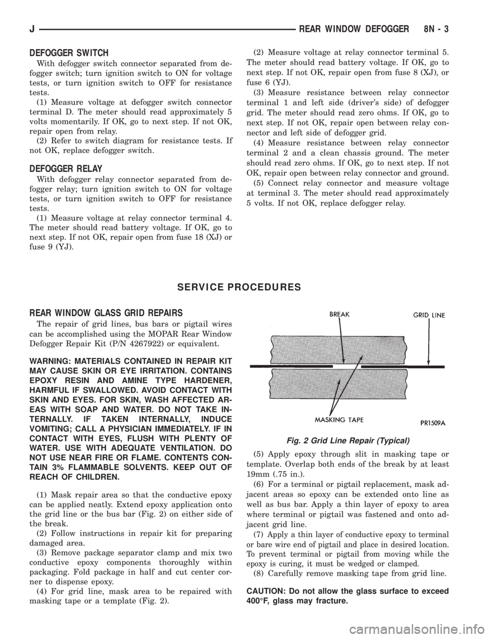
(1) Mask repair area so that the conductive epoxy
can be applied neatly. Extend epoxy application onto
the grid line or the bus bar (Fig. 2) on either side of
the break.
(2) Follow instructions in repair kit for preparing
damaged area.
(3) Remove package separator clamp and mix two
conductive epoxy components thoroughly within
packaging. Fold package in half and cut center cor-
ner to dispense epoxy.
(4) For grid line, mask area to be repaired with
masking tape or a template (Fig. 2).(5) Apply epoxy through slit in masking tape or
template. Overlap both ends of the break by at least
19mm (.75 in.).
(6) For a terminal or pigtail replacement, mask ad-
jacent areas so epoxy can be extended onto line as
well as bus bar. Apply a thin layer of epoxy to area
where terminal or pigtail was fastened and onto ad-
jacent grid line.
(7) Apply a thin layer of conductive epoxy to terminal
or bare wire end of pigtail and place in desired location.
To prevent terminal or pigtail from moving while the
epoxy is curing, it must be wedged or clamped.
(8) Carefully remove masking tape from grid line.
CAUTION: Do not allow the glass surface to exceed
400ÉF, glass may fracture.
Fig. 2 Grid Line Repair (Typical)
JREAR WINDOW DEFOGGER 8N - 3
Page 786 of 2158
Connector # Color Location Fig.
C226......BK ...Left Kick Panel
C227......BK ...OnI.P.Right of Steering Column . . .10
C228......BK ...Left Side of Steering Column.....14
C229......BK ...TopofBrake Pedal Arm.........13
C230......BK ...Left Side of I.P...............12
C231......BK ...Center of I.P.................10
C232......GY ...Left Side of I.P...............12
C233......BK ...Left Side of I.P...............12
C234......BK ...Rear of I.P. Cluster............10
C235......NAT...Rear of I.P. Cluster............10
C236......BK ...OnI.P.Right of Steering Column . . .10
C237......BK ...OnI.P.Right of Steering Column . . .10
C238......BK ...OnI.P.Left of Steering Column....10
C239......RD ...OnI.P.Left of Steering Column....10
C240......BK ...Left Front Door..............17
C241......BK ...Center of I.P.
C242......BK ...Center Bottom of I.P..........9,11
C243......BK ...Center Left of I.P.
C301......DG ...Behind Left Kick Panel
C302......BK ...Near Floor Console
C303......BK ...Bottom Right of Drivers Seat . . .15, 23
C304......BK ...Bottom of Drivers Sear.........15
C305......BK ...Behind Right Kick Panel........17
C306......BK ...Left B Pillar................18
C307......BK ...Near Fuel Tank..............15
C308......BK ...InLiftgate.................24
C309......BK ...Under Rear of Roof Liner........20
C310......BK ...Left Rear Quarter Panel.........20
C311......BK ...Left Rear Quarter Panel.........20
C312......BK ...Left Rear Quarter Panel.........20
C313......BK ...InLiftgate.................24
C314......NAT...InLeft Rear Door.............18
C315......BK ...InLeft Rear Door.............18
C316......RD ...InLeft Rear Door.............18
C317......BK ...Behind Left Kick Panel.......15, 17
C318......RD ...Behind Left Kick Panel.......15, 17
C319......BK ...Under Floor Console...........15
C320......GY ...Under Right Rear Seat.........18
C321......BK ...Behind Right Kick Panel........17
C322......DG ...AtDome Lamp
C323......BK ...InLiftgate.................24
C324......BK ...Right Rear Quarter Panel........20
C325......NAT...InRight Rear Door............18
C326......BK ...InRight Rear Door............18
C327......BK ...InRight Rear Door............18
C328......BK ...InRight B Pillar..............18
C329......BK ...InRight Front Door...........17
C331......BK ...InRight Front Door...........17
C332......BK ...InRight Front Door...........17
C333......BK ...InRight Front Door...........17
C334......BK ...InRight Front Door...........17
C335......BK ...InLeft Front Door............17
C336......BK ...InLeft Front Door............17
C338......BK ...InLeft Front Door............17
C339......BK ...InLeft Front Door............17
C340......BK ...InLeft Front Door............17
C341......BK ...InLeft Front Door............17Connector # Color Location Fig.
C342......BK ...Front Center of Roof Liner.......16
C343......BK ...Behind Overhead Console.......16
C344......BK ...Behind Doom Lamp...........16
C345......BK ...Inleft Rear Corner of Vehicle.....20
C346......BK ...Left Rear Quarter Panel.........20
C347......BK ...Left Rear Quarter Panel.........20
C348......BK ...Left Rear Quarter Panel.........20
C349......BK ...Left Rear Quarter Panel.........20
C350......BK ...InLiftgate.................24
C351......BK ...Left Rear Quarter Panel.........22
C352......BK ...Floor Pan, Near Drivers Seat
C353......BK ...InLiftgate.................25
C354......BK ...Below Left Rear Seat..........19
C355......RD ...Below Left Rear Seat..........19
C356......BK ...Below Left Rear Seat..........19
C357......BK ...OnTransmission.............21
C358......GN ...InLiftgate.................24
C401......BK ...Behind PRNDL..............15
C402......BK ...InFloor Console
C403......BK ...Rear of Radio...............11
C404......BK ...Rear of Transmission (2WD)......21
C404......BK ...Rear of Transfer Case (4WD).....21
C405......BK ...Behind Cargo Lamp...........20
C406......YL ...InLiftgate.................24
C407......BK ...OnTransfer Case.............21
C408......BK ...Side of Transmission
C409......BK ...Right of Radiator............1,3
C410......BK ...InLeft Rear Door
C411......BK ...InLeft Front Door
C412......BK ...InRight Door
C413......BK ...InRight Rear Door
C414......BK ...OnTransfer Case.............21
C415......BK ...Near Underhood Lamp
C416......BK ...Behind Lens
C417......BK ...Behind Lens
C418......YL ...Behind Lens
C419......YL ...Behind Lens
C420......BK ...Behind Lens
C421......BK ...Behind Lens
C422......BK ...Behind Lens
C423......BK ...Behind Lens
C424......BK ...Side of Drivers Seat...........23
C425......BK ...Below Drivers Seat............23
C426......BK ...Behind Lens................25
C427......BK ...Behind Lens................25
C428......BK ...AtAshReceiver..............12
C429......BK ...InLiftgate.................24
C430......BK ...InLiftgate.................24
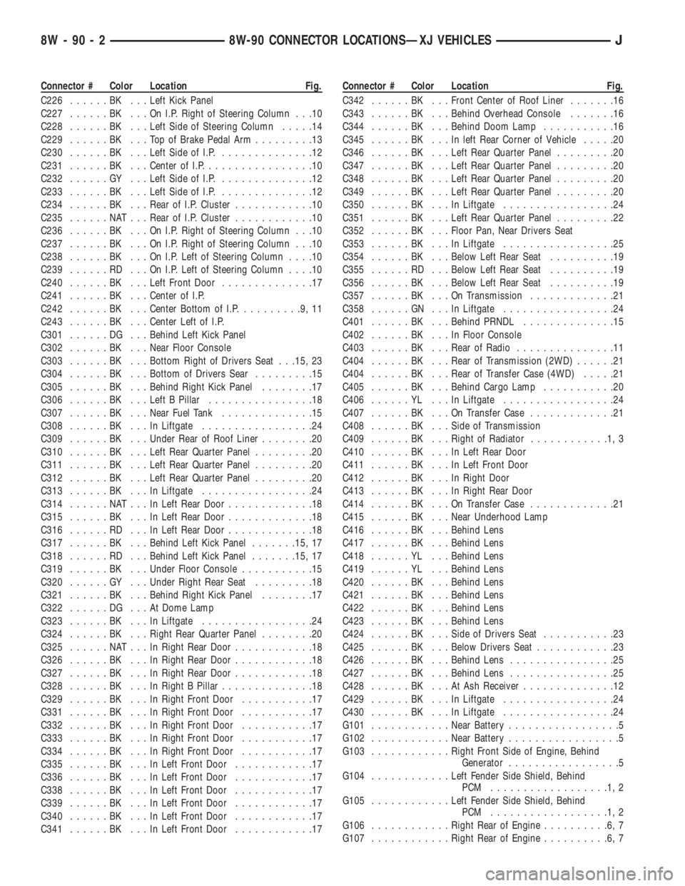
G101............Near Battery.................5
G102............Near Battery.................5
G103............Right Front Side of Engine, Behind
Generator.................5
G104............Left Fender Side Shield, Behind
PCM ..................1,2
G105............Left Fender Side Shield, Behind
PCM ..................1,2
G106............Right Rear of Engine..........6,7
G107............Right Rear of Engine..........6,7
8W - 90 - 2 8W-90 CONNECTOR LOCATIONSÐXJ VEHICLESJ
Page 792 of 2158
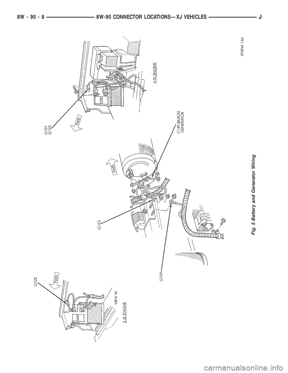
Fig. 5 Battery and Generator Wiring
8W - 90 - 8 8W-90 CONNECTOR LOCATIONSÐXJ VEHICLESJ
Page 1067 of 2158
CONNECTOR LOCATIONS
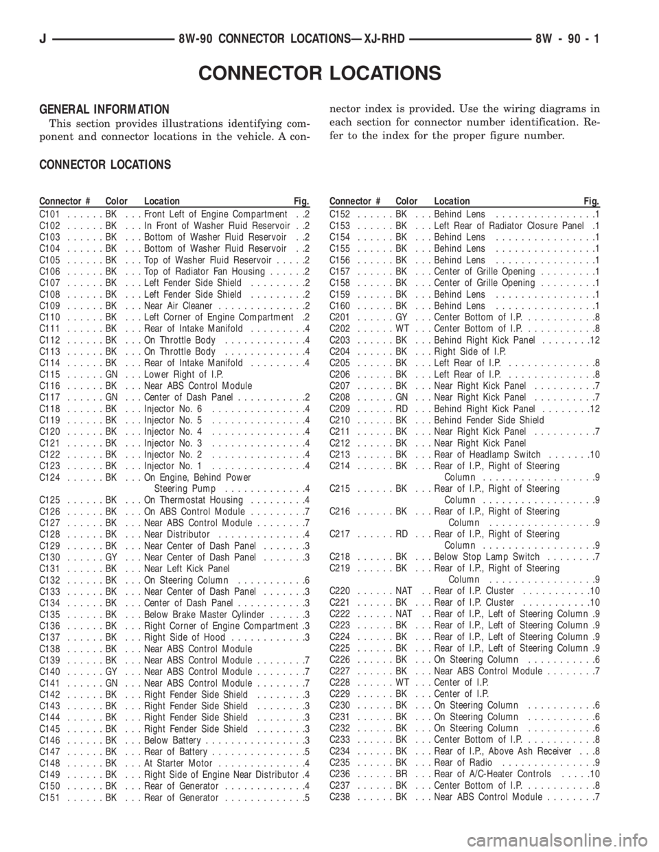
GENERAL INFORMATION
This section provides illustrations identifying com-
ponent and connector locations in the vehicle. A con-nector index is provided. Use the wiring diagrams in
each section for connector number identification. Re-
fer to the index for the proper figure number.
CONNECTOR LOCATIONS
Connector # Color Location Fig.
C101......BK ...Front Left of Engine Compartment . .2
C102......BK ...InFront of Washer Fluid Reservoir . .2
C103......BK ...Bottom of Washer Fluid Reservoir . .2
C104......BK ...Bottom of Washer Fluid Reservoir . .2
C105......BK ...TopofWasher Fluid Reservoir.....2
C106......BK ...TopofRadiator Fan Housing......2
C107......BK ...Left Fender Side Shield.........2
C108......BK ...Left Fender Side Shield.........2
C109......BK ...Near Air Cleaner..............2
C110......BK ...Left Corner of Engine Compartment .2
C111......BK ...Rear of Intake Manifold.........4
C112......BK ...OnThrottle Body.............4
C113......BK ...OnThrottle Body.............4
C114......BK ...Rear of Intake Manifold.........4
C115......GN ...Lower Right of I.P.
C116......BK ...Near ABS Control Module
C117......GN ...Center of Dash Panel...........2
C118......BK ...Injector No. 6...............4
C119......BK ...Injector No. 5...............4
C120......BK ...Injector No. 4...............4
C121......BK ...Injector No. 3...............4
C122......BK ...Injector No. 2...............4
C123......BK ...Injector No. 1...............4
C124......BK ...OnEngine, Behind Power
Steering Pump.............4
C125......BK ...OnThermostat Housing.........4
C126......BK ...OnABSControl Module.........7
C127......BK ...Near ABS Control Module........7
C128......BK ...Near Distributor..............4
C129......BK ...Near Center of Dash Panel.......3
C130......GY ...Near Center of Dash Panel.......3
C131......BK ...Near Left Kick Panel
C132......BK ...OnSteering Column...........6
C133......BK ...Near Center of Dash Panel.......3
C134......BK ...Center of Dash Panel...........3
C135......BK ...Below Brake Master Cylinder......3
C136......BK ...Right Corner of Engine Compartment .3
C137......BK ...Right Side of Hood............3
C138......BK ...Near ABS Control Module
C139......BK ...Near ABS Control Module........7
C140......GY ...Near ABS Control Module........7
C141......GN ...Near ABS Control Module........7
C142......BK ...Right Fender Side Shield........3
C143......BK ...Right Fender Side Shield........3
C144......BK ...Right Fender Side Shield........3
C145......BK ...Right Fender Side Shield........3
C146......BK ...Below Battery................3
C147......BK ...Rear of Battery...............5
C148......BK ...AtStarter Motor..............4
C149......BK ...Right Side of Engine Near Distributor .4
C150......BK ...Rear of Generator.............4
C151......BK ...Rear of Generator.............5Connector # Color Location Fig.
C152......BK ...Behind Lens................1
C153......BK ...Left Rear of Radiator Closure Panel .1
C154......BK ...Behind Lens................1
C155......BK ...Behind Lens................1
C156......BK ...Behind Lens................1
C157......BK ...Center of Grille Opening.........1
C158......BK ...Center of Grille Opening.........1
C159......BK ...Behind Lens................1
C160......BK ...Behind Lens................1
C201......GY ...Center Bottom of I.P............8
C202......WT ...Center Bottom of I.P............8
C203......BK ...Behind Right Kick Panel........12
C204......BK ...Right Side of I.P.
C205......BK ...Left Rear of I.P...............8
C206......BK ...Left Rear of I.P...............8
C207......BK ...Near Right Kick Panel..........7
C208......GN ...Near Right Kick Panel..........7
C209......RD ...Behind Right Kick Panel........12
C210......BK ...Behind Fender Side Shield
C211......BK ...Near Right Kick Panel..........7
C212......BK ...Near Right Kick Panel
C213......BK ...Rear of Headlamp Switch.......10
C214......BK ...Rear of I.P., Right of Steering
Column..................9
C215......BK ...Rear of I.P., Right of Steering
Column..................9
C216......BK ...Rear of I.P., Right of Steering
Column.................9
C217......RD ...Rear of I.P., Right of Steering
Column..................9
C218......BK ...Below Stop Lamp Switch........7
C219......BK ...Rear of I.P., Right of Steering
Column.................9
C220......NAT ..Rear of I.P. Cluster...........10
C221......BK ...Rear of I.P. Cluster...........10
C222......NAT ..Rear of I.P., Left of Steering Column .9
C223......BK ...Rear of I.P., Left of Steering Column .9
C224......BK ...Rear of I.P., Left of Steering Column .9
C225......BK ...Rear of I.P., Left of Steering Column .9
C226......BK ...OnSteering Column...........6
C227......BK ...Near ABS Control Module........7
C228......WT ...Center of I.P.
C229......BK ...Center of I.P.
C230......BK ...OnSteering Column...........6
C231......BK ...OnSteering Column...........6
C232......BK ...OnSteering Column...........6
C233......BK ...Center Bottom of I.P............8
C234......BK ...Rear of I.P., Above Ash Receiver . . .8
C235......BK ...Rear of Radio...............9
C236......BR ...Rear of A/C-Heater Controls.....10
C237......BK ...Center Bottom of I.P............8
C238......BK ...Near ABS Control Module........7
J8W-90 CONNECTOR LOCATIONSÐXJ-RHD 8W - 90 - 1
Page 1068 of 2158
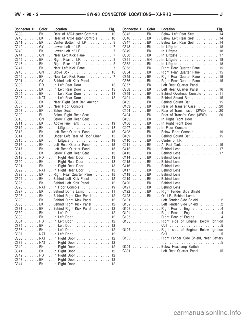
Connector # Color Location Fig.
C239......BK ...Rear of A/C-Heater Controls.....10
C240......BK ...Rear of A/C-Heater Controls.....10
C241......BK ...Center Bottom of I.P............8
C242......GY ...Lower Left of I.P..............7
C243......BK ...Lower Left of I.P..............7
C244......GN ...Near Left Kick Panel...........7
C245......BK ...Right Rear of I.P..............8
C246......BK ...Right Rear of I.P..............8
C247......BK ...Near Left Kick Panel...........7
C248......GN ...Glove Box.................10
C249......BK ...Near Left Kick Panel...........7
C301......GY ...Behind Left Kick Panel
C302......RD ...InLeft Rear Door............13
C303......BK ...InLeft Rear Door............13
C304......BK ...InLeft Rear Door............13
C305......NAT ..InLeft Rear Door............13
C306......BK ...Near Right Seat Belt Anchor
C307......BK ...Near Floor Console
C308......BK ...Below Seat
C309......BL ...Below Right Rear Seat
C310......GN ...Below Right Rear Seat
C311......BK ...Above Fuel Tank.............19
C312......BK ...InLiftgate.................18
C313......BK ...Left Rear Quarter Panel........15
C314......BK ...Under Left Rear of Roof Liner....15
C315......BK ...InLiftgate.................18
C316......BK ...Left Rear Quarter Panel........15
C317......BK ...Left Rear Quarter Panel........15
C318......BK ...Below Right Rear Seat.........13
C319......RD ...InRight Rear Door...........13
C320......BK ...InRight Rear Door...........13
C321......BK ...InRight Rear Door...........13
C322......NAT ..InRight Rear Door...........13
C323......BK ...Right Rear Quarter Panel.......15
C324......BK ...Behind Left Kick Panel.........12
C325......BK ...Behind Left Kick Panel.........12
C326......NAT ..InFloor Console.............19
C327......BK ...Behind Dome Lamp...........11
C328......BK ...Behind Right Kick Panel........12
C329......BK ...Behind Right Kick Panel........12
C330......BK ...Behind Right Kick Panel........12
C331......BK ...Behind Right Kick Panel........12
C332......BK ...InLeft Door................12
C333......BK ...InLeft Door................12
C334......RD ...InLeft Door................12
C335......BK ...InLeft Door................12
C336......BK ...InLeft Door................12
C337......NAT ..InLeft Door................12
C338......NAT ..InRight Door...............12
C339......NAT ..InRight Door...............12
C340......BK ...InRight Door...............12
C341......BK ...InRight Door...............12
C342......RD ...InRight Door...............12
C343......BK ...InRight Door...............12
C344......BK ...InRight Door...............12Connector # Color Location Fig.
C345......BK ...Below Left Rear Seat..........14
C346......BK ...Below Left Rear Seat..........14
C347......BK ...Below Left Rear Seat..........14
C348......BK ...InLiftgate.................18
C349......BK ...InLiftgate.................18
C350......BK ...InLiftgate.................17
C351......GN ...InLiftgate.................18
C352......BK ...InLiftgate.................18
C353......BK ...Right Rear Quarter Panel.......15
C354......BK ...Right Rear Quarter Panel.......15
C355......BK ...Right Rear Quarter Panel.......15
C356......BK ...Right Rear Quarter Panel.......15
C357......BK ...Left Rear Quarter Panel
C358......BK ...Left Rear Quarter Panel........16
C359......BK ...Behind Overhead Console.......11
C401......BK ...Behind Sound Bar............15
C402......BK ...Behind Sound Bar............15
C403......BK ...Rear of Transfer Case.........20
C404......BK ...Rear of Transmission (2WD).....20
C404......BK ...Rear of Transfer Case (4WD).....20
C405......BK ...InRight Front Door
C406......BK ...InRight Front Door
C407......BK ...InFloor Console
C408......BK ...Below Floor Console..........19
C409......BK ...Behind Sound Bar............15
C410......BK ...Center of I.P.
C411......BK ...AtFuel Tank................19
C412......BK ...Behind Lens................17
C413......BK ...Behind Lens................17
C414......BK ...Behind Lens
C415......BK ...Behind Lens
C416......BK ...Behind Lens
C417......BK ...Behind Lens
C418......BK ...Behind Lens
C419......BK ...Behind Lens
C420......BK ...Behind Lens
C421......BK ...Behind Lens
C422......BK ...Right Fender Side Shield
C423......BK ...OnI.P.,Behind Lamp
G101............Left Fender Side Shield.........2
G102............Left Fender Side Shield.........2
G103............Right Rear of Engine...........4
G104............Right Rear of Engine...........4
G105............Right Rear of Engine...........4
G106............Right side of Engine, Below Ignition
Coil......................5
G107............Right side of Engine, Below Ignition
Coil......................5
G108............Right Fender Side Shield, Near Battery
.........................5
G201............Below Headlamp Switch
G301............Left Rear Quarter Panel........15
8W - 90 - 2 8W-90 CONNECTOR LOCATIONSÐXJ-RHDJ
Page 1073 of 2158
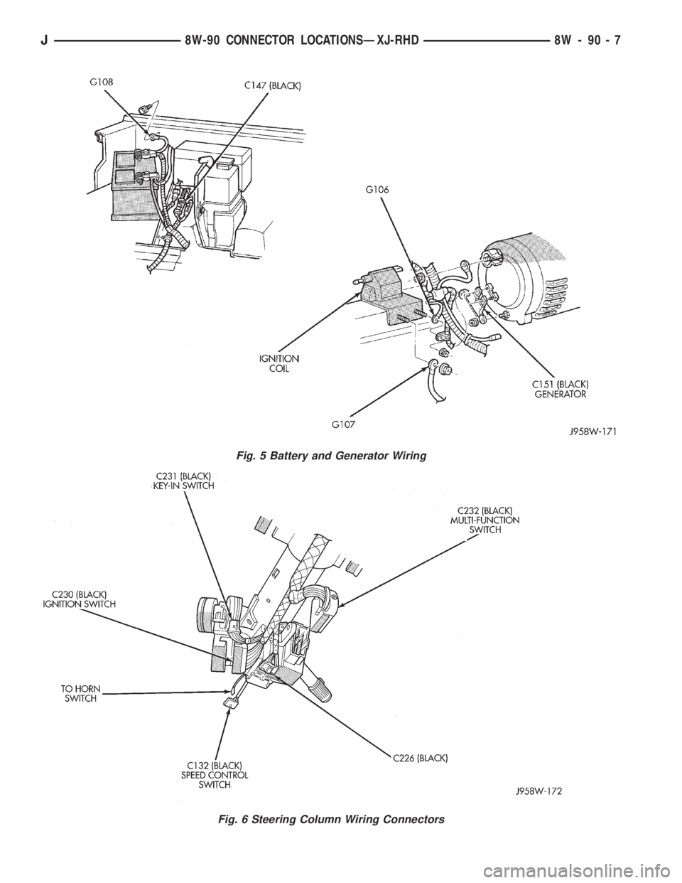
Fig. 5 Battery and Generator Wiring
Fig. 6 Steering Column Wiring Connectors
J8W-90 CONNECTOR LOCATIONSÐXJ-RHD 8W - 90 - 7
Page 1262 of 2158
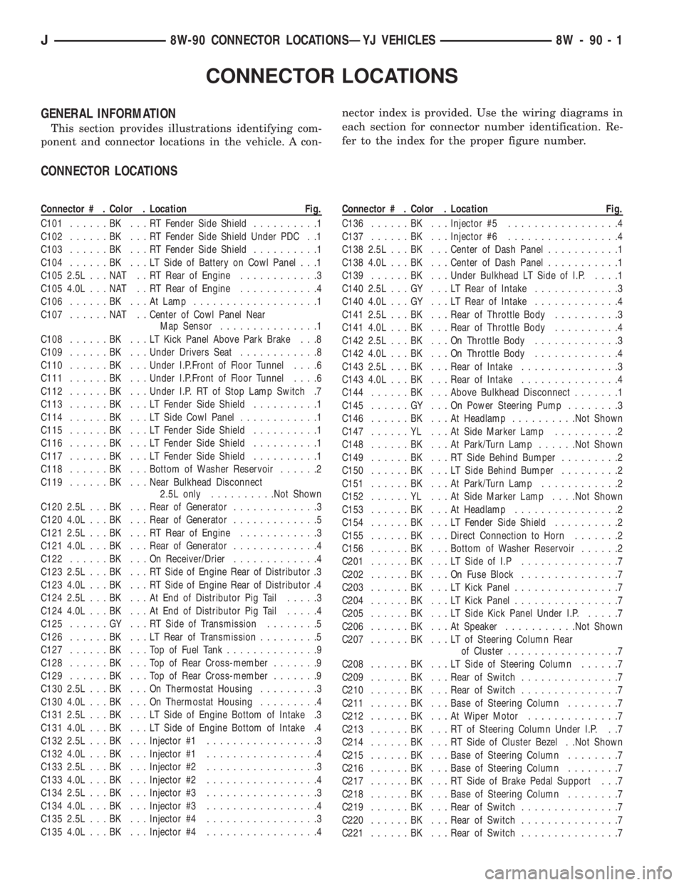
CONNECTOR LOCATIONS
GENERAL INFORMATION
This section provides illustrations identifying com-
ponent and connector locations in the vehicle. A con-nector index is provided. Use the wiring diagrams in
each section for connector number identification. Re-
fer to the index for the proper figure number.
CONNECTOR LOCATIONS
Connector # . Color . Location Fig.
C101......BK ...RTFender Side Shield..........1
C102......BK ...RTFender Side Shield Under PDC . .1
C103......BK ...RTFender Side Shield..........1
C104......BK ...LTSide of Battery on Cowl Panel . . .1
C105 2.5L . . . NAT . . RT Rear of Engine............3
C105 4.0L . . . NAT . . RT Rear of Engine............4
C106......BK ...AtLamp...................1
C107......NAT ..Center of Cowl Panel Near
Map Sensor...............1
C108......BK ...LTKick Panel Above Park Brake . . .8
C109......BK ...Under Drivers Seat............8
C110......BK ...Under I.P.Front of Floor Tunnel....6
C111......BK ...Under I.P.Front of Floor Tunnel....6
C112......BK ...Under I.P. RT of Stop Lamp Switch .7
C113......BK ...LTFender Side Shield..........1
C114......BK ...LTSide Cowl Panel............1
C115......BK ...LTFender Side Shield..........1
C116......BK ...LTFender Side Shield..........1
C117......BK ...LTFender Side Shield..........1
C118......BK ...Bottom of Washer Reservoir......2
C119......BK ...Near Bulkhead Disconnect
2.5L only..........Not Shown
C120 2.5L . . . BK . . . Rear of Generator.............3
C120 4.0L . . . BK . . . Rear of Generator.............5
C121 2.5L . . . BK . . . RT Rear of Engine............3
C121 4.0L . . . BK . . . Rear of Generator.............4
C122......BK ...OnReceiver/Drier.............4
C123 2.5L . . . BK . . . RT Side of Engine Rear of Distributor .3
C123 4.0L . . . BK . . . RT Side of Engine Rear of Distributor .4
C124 2.5L . . . BK . . . At End of Distributor Pig Tail.....3
C124 4.0L . . . BK . . . At End of Distributor Pig Tail.....4
C125......GY ...RTSide of Transmission........5
C126......BK ...LTRear of Transmission.........5
C127......BK ...TopofFuel Tank..............9
C128......BK ...TopofRear Cross-member.......9
C129......BK ...TopofRear Cross-member.......9
C130 2.5L . . . BK . . . On Thermostat Housing.........3
C130 4.0L . . . BK . . . On Thermostat Housing.........4
C131 2.5L . . . BK . . . LT Side of Engine Bottom of Intake .3
C131 4.0L . . . BK . . . LT Side of Engine Bottom of Intake .4
C132 2.5L . . . BK . . . Injector #1.................3
C132 4.0L . . . BK . . . Injector #1.................4
C133 2.5L . . . BK . . . Injector #2.................3
C133 4.0L . . . BK . . . Injector #2.................4
C134 2.5L . . . BK . . . Injector #3.................3
C134 4.0L . . . BK . . . Injector #3.................4
C135 2.5L . . . BK . . . Injector #4.................3
C135 4.0L . . . BK . . . Injector #4.................4Connector # . Color . Location Fig.
C136......BK ...Injector #5.................4
C137......BK ...Injector #6.................4
C138 2.5L . . . BK . . . Center of Dash Panel...........1
C138 4.0L . . . BK . . . Center of Dash Panel...........1
C139......BK ...Under Bulkhead LT Side of I.P.....1
C140 2.5L . . . GY . . . LT Rear of Intake.............3
C140 4.0L . . . GY . . . LT Rear of Intake.............4
C141 2.5L . . . BK . . . Rear of Throttle Body..........3
C141 4.0L . . . BK . . . Rear of Throttle Body..........4
C142 2.5L . . . BK . . . On Throttle Body.............3
C142 4.0L . . . BK . . . On Throttle Body.............4
C143 2.5L . . . BK . . . Rear of Intake...............3
C143 4.0L . . . BK . . . Rear of Intake...............4
C144......BK ...Above Bulkhead Disconnect.......1
C145......GY ...OnPower Steering Pump........3
C146......BK ...AtHeadlamp..........Not Shown
C147......YL ...AtSide Marker Lamp..........2
C148......BK ...AtPark/Turn Lamp......Not Shown
C149......BK ...RTSide Behind Bumper.........2
C150......BK ...LTSide Behind Bumper.........2
C151......BK ...AtPark/Turn Lamp............2
C152......YL ...AtSide Marker Lamp. . . .Not Shown
C153......BK ...AtHeadlamp................2
C154......BK ...LTFender Side Shield..........2
C155......BK ...Direct Connection to Horn.......2
C156......BK ...Bottom of Washer Reservoir......2
C201......BK ...LTSide of I.P...............7
C202......BK ...OnFuse Block...............7
C203......BK ...LTKick Panel................7
C204......BK ...LTKick Panel................7
C205......BK ...LTSide Kick Panel Under I.P......7
C206......BK ...AtSpeaker...........Not Shown
C207......BK ...LTofSteering Column Rear
of Cluster.................7
C208......BK ...LTSide of Steering Column......7
C209......BK ...Rear of Switch...............7
C210......BK ...Rear of Switch...............7
C211......BK ...Base of Steering Column........7
C212......BK ...AtWiper Motor..............7
C213......BK ...RTofSteering Column Under I.P. . .7
C214......BK ...RTSide of Cluster Bezel . .Not Shown
C215......BK ...Base of Steering Column........7
C216......BK ...Base of Steering Column........7
C217......BK ...RTSide of Brake Pedal Support . . .7
C218......BK ...Base of Steering Column........7
C219......BK ...Rear of Switch...............7
C220......BK ...Rear of Switch...............7
C221......BK ...Rear of Switch...............7
J8W-90 CONNECTOR LOCATIONSÐYJ VEHICLES 8W - 90 - 1
Page 1263 of 2158
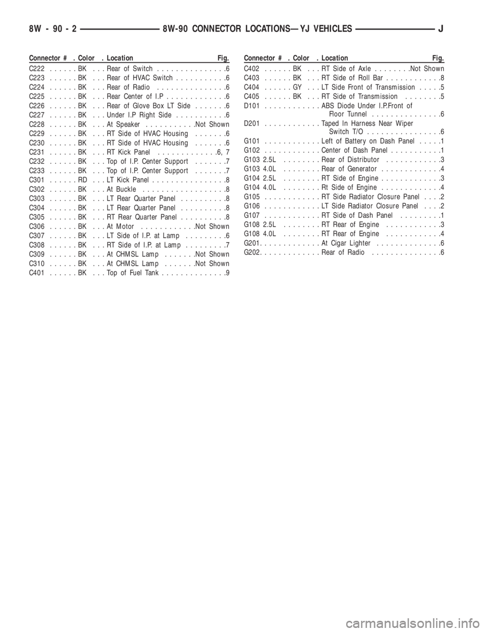
Connector # . Color . Location Fig.
C222......BK ...Rear of Switch...............6
C223......BK ...Rear of HVAC Switch...........6
C224......BK ...Rear of Radio...............6
C225......BK ...Rear Center of I.P.............6
C226......BK ...Rear of Glove Box LT Side.......6
C227......BK ...Under I.P Right Side...........6
C228......BK ...AtSpeaker...........Not Shown
C229......BK ...RTSide of HVAC Housing.......6
C230......BK ...RTSide of HVAC Housing.......6
C231......BK ...RTKick Panel.............6,7
C232......BK ...TopofI.P.Center Support.......7
C233......BK ...TopofI.P.Center Support.......7
C301......RD ...LTKick Panel................8
C302......BK ...AtBuckle..................8
C303......BK ...LTRear Quarter Panel..........8
C304......BK ...LTRear Quarter Panel..........8
C305......BK ...RTRear Quarter Panel..........8
C306......BK ...AtMotor............Not Shown
C307......BK ...LTSide of I.P. at Lamp.........6
C308......BK ...RTSide of I.P. at Lamp.........7
C309......BK ...AtCHMSL Lamp.......Not Shown
C310......BK ...AtCHMSL Lamp.......Not Shown
C401......BK ...TopofFuel Tank..............9Connector # . Color . Location Fig.
C402......BK ...RTSide of Axle........Not Shown
C403......BK ...RTSide of Roll Bar............8
C404......GY ...LTSide Front of Transmission.....5
C405......BK ...RTSide of Transmission........5
D101............ABSDiode Under I.P.Front of
Floor Tunnel...............6
D201............Taped In Harness Near Wiper
Switch T/O................6
G101............Left of Battery on Dash Panel.....1
G102............Center of Dash Panel...........1
G103 2.5L . .......Rear of Distributor............3
G103 4.0L . .......Rear of Generator.............4
G104 2.5L . .......RTSide of Engine.............3
G104 4.0L . .......RtSide of Engine.............4
G105............RTSide Radiator Closure Panel....2
G106............LTSide Radiator Closure Panel....2
G107............RTSide of Dash Panel.........1
G108 2.5L . .......RTRear of Engine............3
G108 4.0L . .......RTRear of Engine............4
G201.............AtCigar Lighter..............6
G202.............Rear of Radio...............6
8W - 90 - 2 8W-90 CONNECTOR LOCATIONSÐYJ VEHICLESJ