1995 JEEP YJ air suspension
[x] Cancel search: air suspensionPage 122 of 2158
²Smooth appearance with no broken/dented sur-
faces on the bearing rollers or the roller contact sur-
faces
²Bearing cups must not be distorted or cracked
²Machined surfaces should be smooth and without
any raised edges
²Raised metal on shoulders of cup bores should be
removed with a hand stone
²Wear and damage to pinion gear mate shaft, pin-
ion gears, side gears and thrust washers. Replace as
a matched set only.
²Ring and pinion gear for worn and chipped teeth
²Ring gear for damaged bolt threads. Replaced as a
matched set only.
²Pinion yoke for cracks, worn splines, pitted areas,
and a rough/corroded seal contact surface. Repair or
replace as necessary.
²Preload shims for damage and distortion. Install
new shims if necessary.
DIFFERENTIAL ASSEMBLY
(1) Install the following components in the differ-
ential case.
²Differential side gears and thrust washers
²Pinion gears and thrust washers
²Pinion gear mate shaft (align holes in shaft and
case)
(2) Lubricate all differential components with hy-
poid gear lubricant.
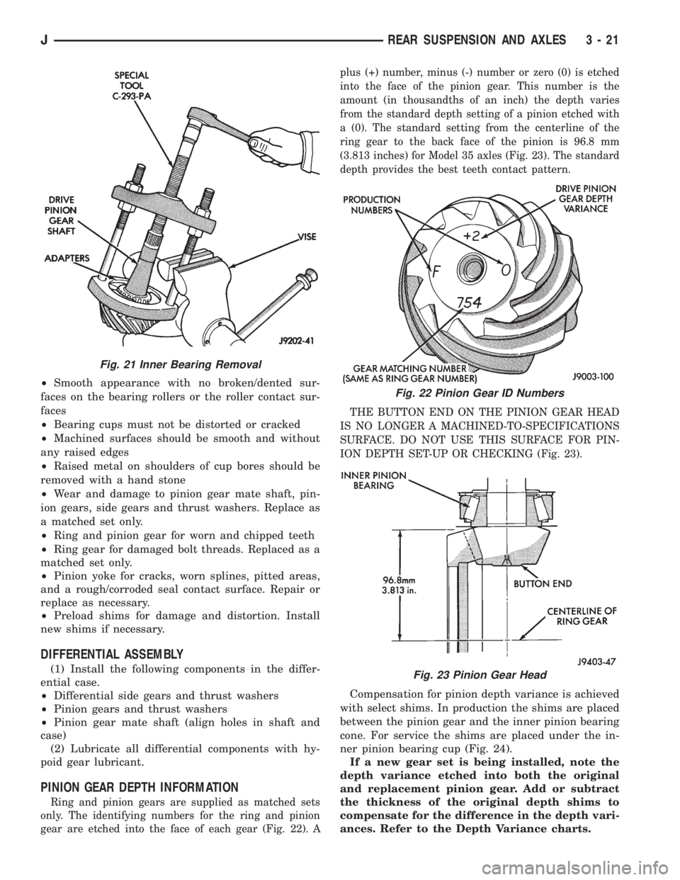
PINION GEAR DEPTH INFORMATION
Ring and pinion gears are supplied as matched sets
only. The identifying numbers for the ring and pinion
gear are etched into the face of each gear (Fig. 22). Aplus (+) number, minus (-) number or zero (0) is etched
into the face of the pinion gear. This number is the
amount (in thousandths of an inch) the depth varies
from the standard depth setting of a pinion etched with
a (0). The standard setting from the centerline of the
ring gear to the back face of the pinion is 96.8 mm
(3.813 inches) for Model 35 axles (Fig. 23). The standard
depth provides the best teeth contact pattern.
THE BUTTON END ON THE PINION GEAR HEAD
IS NO LONGER A MACHINED-TO-SPECIFICATIONS
SURFACE. DO NOT USE THIS SURFACE FOR PIN-
ION DEPTH SET-UP OR CHECKING (Fig. 23).
Compensation for pinion depth variance is achieved
with select shims. In production the shims are placed
between the pinion gear and the inner pinion bearing
cone. For service the shims are placed under the in-
ner pinion bearing cup (Fig. 24).
If a new gear set is being installed, note the
depth variance etched into both the original
and replacement pinion gear. Add or subtract
the thickness of the original depth shims to
compensate for the difference in the depth vari-
ances. Refer to the Depth Variance charts.
Fig. 21 Inner Bearing Removal
Fig. 22 Pinion Gear ID Numbers
Fig. 23 Pinion Gear Head
JREAR SUSPENSION AND AXLES 3 - 21
Page 135 of 2158
INSTALLATION
(1) Examine the splines on the pinion shaft for
burrs or wear.
(2) Remove any burrs and clean the shaft.
(3) Inspect the pinion yoke for cracks, worn splines
and a worn seal contact surface. Repair or replace
the yoke as necessary.
The outer perimeter of the seal is pre-coated
with a special sealant. An additional applica-
tion of sealant is not required.
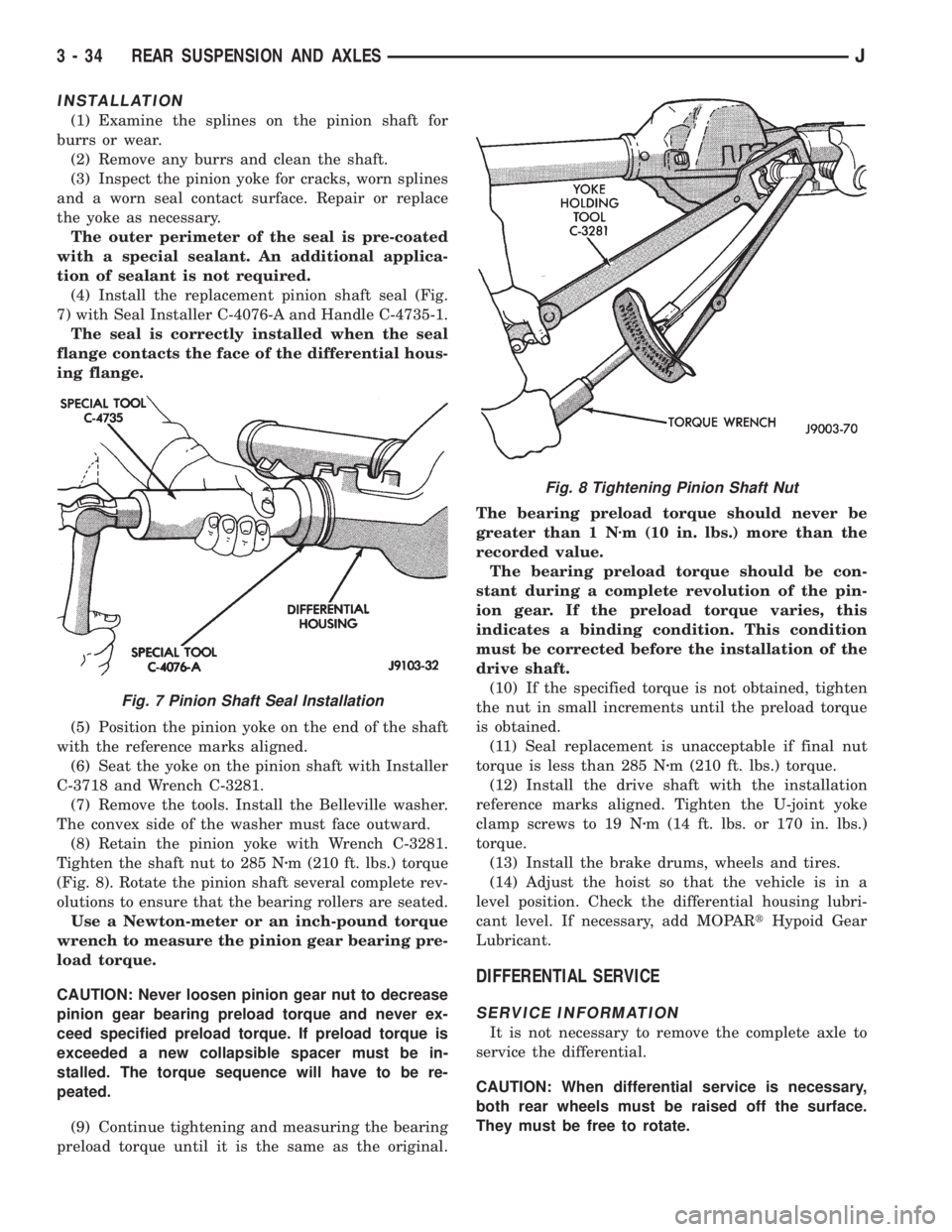
(4) Install the replacement pinion shaft seal (Fig.
7) with Seal Installer C-4076-A and Handle C-4735-1.
The seal is correctly installed when the seal
flange contacts the face of the differential hous-
ing flange.
(5) Position the pinion yoke on the end of the shaft
with the reference marks aligned.
(6) Seat the yoke on the pinion shaft with Installer
C-3718 and Wrench C-3281.
(7) Remove the tools. Install the Belleville washer.
The convex side of the washer must face outward.
(8) Retain the pinion yoke with Wrench C-3281.
Tighten the shaft nut to 285 Nzm (210 ft. lbs.) torque
(Fig. 8). Rotate the pinion shaft several complete rev-
olutions to ensure that the bearing rollers are seated.
Use a Newton-meter or an inch-pound torque
wrench to measure the pinion gear bearing pre-
load torque.
CAUTION: Never loosen pinion gear nut to decrease
pinion gear bearing preload torque and never ex-
ceed specified preload torque. If preload torque is
exceeded a new collapsible spacer must be in-
stalled. The torque sequence will have to be re-
peated.
(9) Continue tightening and measuring the bearing
preload torque until it is the same as the original.The bearing preload torque should never be
greater than 1 Nzm (10 in. lbs.) more than the
recorded value.
The bearing preload torque should be con-
stant during a complete revolution of the pin-
ion gear. If the preload torque varies, this
indicates a binding condition. This condition
must be corrected before the installation of the
drive shaft.
(10) If the specified torque is not obtained, tighten
the nut in small increments until the preload torque
is obtained.
(11) Seal replacement is unacceptable if final nut
torque is less than 285 Nzm (210 ft. lbs.) torque.
(12) Install the drive shaft with the installation
reference marks aligned. Tighten the U-joint yoke
clamp screws to 19 Nzm (14 ft. lbs. or 170 in. lbs.)
torque.
(13) Install the brake drums, wheels and tires.
(14) Adjust the hoist so that the vehicle is in a
level position. Check the differential housing lubri-
cant level. If necessary, add MOPARtHypoid Gear
Lubricant.
DIFFERENTIAL SERVICE
SERVICE INFORMATION
It is not necessary to remove the complete axle to
service the differential.
CAUTION: When differential service is necessary,
both rear wheels must be raised off the surface.
They must be free to rotate.
Fig. 7 Pinion Shaft Seal Installation
Fig. 8 Tightening Pinion Shaft Nut
3 - 34 REAR SUSPENSION AND AXLESJ
Page 138 of 2158
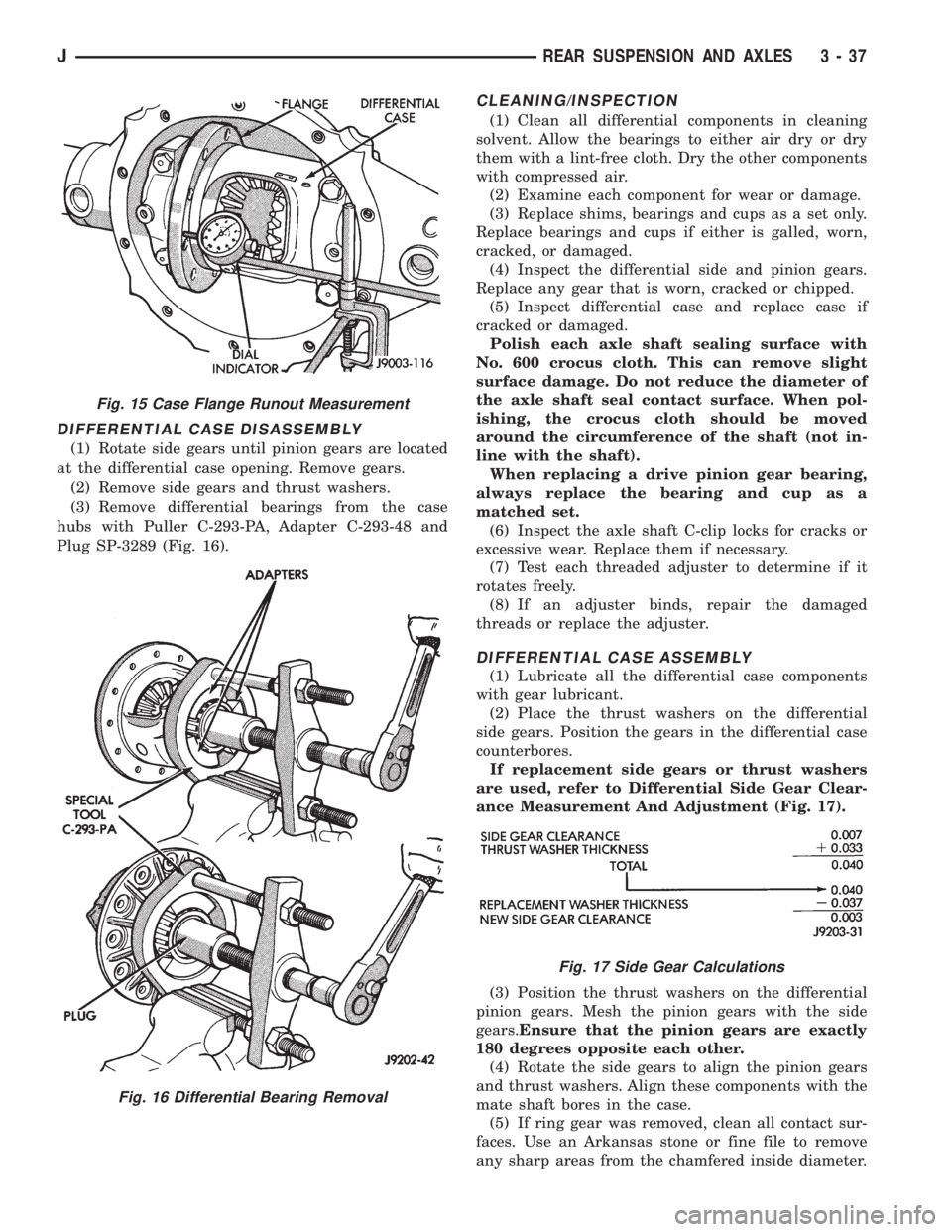
DIFFERENTIAL CASE DISASSEMBLY
(1) Rotate side gears until pinion gears are located
at the differential case opening. Remove gears.
(2) Remove side gears and thrust washers.
(3) Remove differential bearings from the case
hubs with Puller C-293-PA, Adapter C-293-48 and
Plug SP-3289 (Fig. 16).
CLEANING/INSPECTION
(1) Clean all differential components in cleaning
solvent. Allow the bearings to either air dry or dry
them with a lint-free cloth. Dry the other components
with compressed air.
(2) Examine each component for wear or damage.
(3) Replace shims, bearings and cups as a set only.
Replace bearings and cups if either is galled, worn,
cracked, or damaged.
(4) Inspect the differential side and pinion gears.
Replace any gear that is worn, cracked or chipped.
(5) Inspect differential case and replace case if
cracked or damaged.
Polish each axle shaft sealing surface with
No. 600 crocus cloth. This can remove slight
surface damage. Do not reduce the diameter of
the axle shaft seal contact surface. When pol-
ishing, the crocus cloth should be moved
around the circumference of the shaft (not in-
line with the shaft).
When replacing a drive pinion gear bearing,
always replace the bearing and cup as a
matched set.
(6) Inspect the axle shaft C-clip locks for cracks or
excessive wear. Replace them if necessary.
(7) Test each threaded adjuster to determine if it
rotates freely.
(8) If an adjuster binds, repair the damaged
threads or replace the adjuster.
DIFFERENTIAL CASE ASSEMBLY
(1) Lubricate all the differential case components
with gear lubricant.
(2) Place the thrust washers on the differential
side gears. Position the gears in the differential case
counterbores.
If replacement side gears or thrust washers
are used, refer to Differential Side Gear Clear-
ance Measurement And Adjustment (Fig. 17).
(3) Position the thrust washers on the differential
pinion gears. Mesh the pinion gears with the side
gears.Ensure that the pinion gears are exactly
180 degrees opposite each other.
(4) Rotate the side gears to align the pinion gears
and thrust washers. Align these components with the
mate shaft bores in the case.
(5) If ring gear was removed, clean all contact sur-
faces. Use an Arkansas stone or fine file to remove
any sharp areas from the chamfered inside diameter.
Fig. 15 Case Flange Runout Measurement
Fig. 16 Differential Bearing Removal
Fig. 17 Side Gear Calculations
JREAR SUSPENSION AND AXLES 3 - 37
Page 143 of 2158
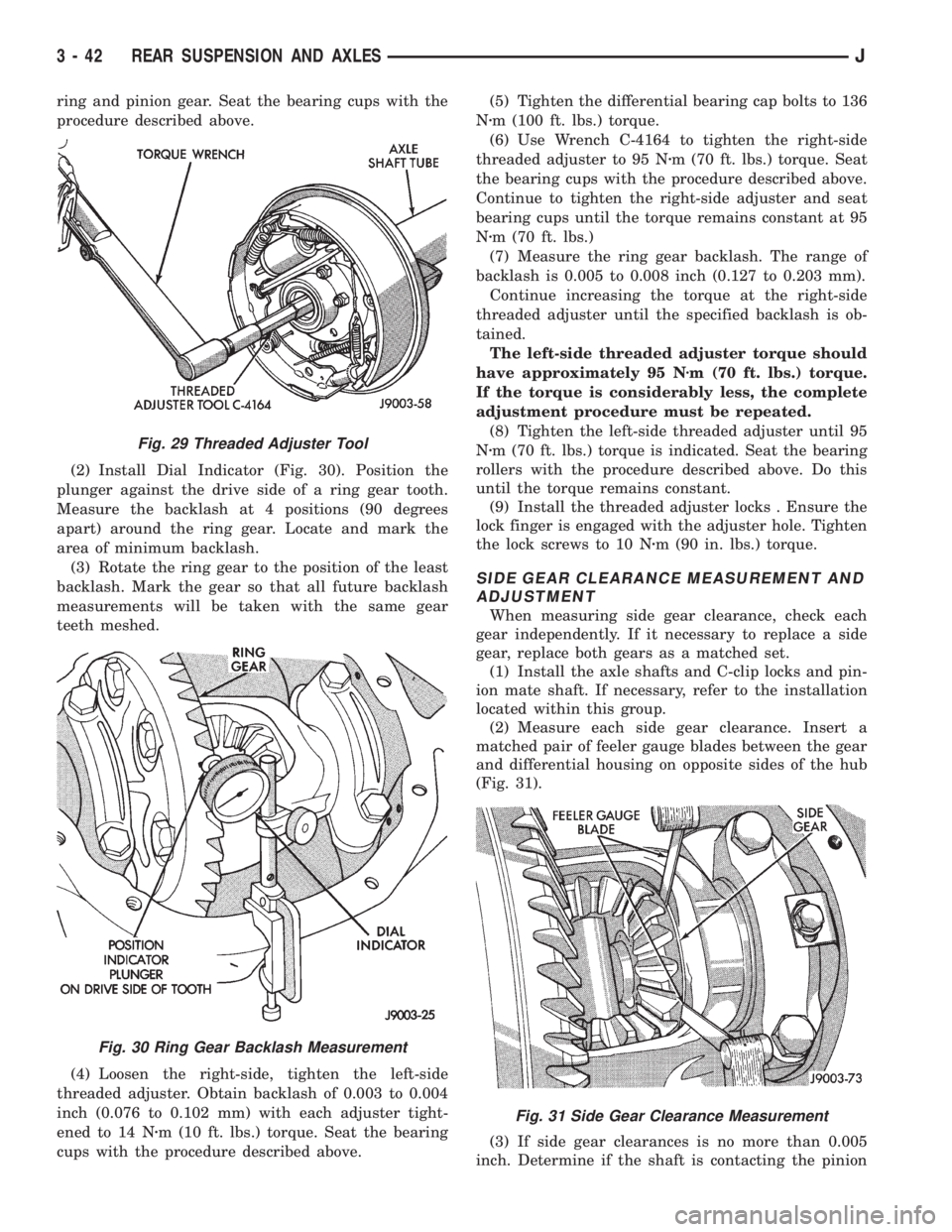
ring and pinion gear. Seat the bearing cups with the
procedure described above.
(2) Install Dial Indicator (Fig. 30). Position the
plunger against the drive side of a ring gear tooth.
Measure the backlash at 4 positions (90 degrees
apart) around the ring gear. Locate and mark the
area of minimum backlash.
(3) Rotate the ring gear to the position of the least
backlash. Mark the gear so that all future backlash
measurements will be taken with the same gear
teeth meshed.
(4) Loosen the right-side, tighten the left-side
threaded adjuster. Obtain backlash of 0.003 to 0.004
inch (0.076 to 0.102 mm) with each adjuster tight-
ened to 14 Nzm (10 ft. lbs.) torque. Seat the bearing
cups with the procedure described above.(5) Tighten the differential bearing cap bolts to 136
Nzm (100 ft. lbs.) torque.
(6) Use Wrench C-4164 to tighten the right-side
threaded adjuster to 95 Nzm (70 ft. lbs.) torque. Seat
the bearing cups with the procedure described above.
Continue to tighten the right-side adjuster and seat
bearing cups until the torque remains constant at 95
Nzm (70 ft. lbs.)
(7) Measure the ring gear backlash. The range of
backlash is 0.005 to 0.008 inch (0.127 to 0.203 mm).
Continue increasing the torque at the right-side
threaded adjuster until the specified backlash is ob-
tained.
The left-side threaded adjuster torque should
have approximately 95 Nzm (70 ft. lbs.) torque.
If the torque is considerably less, the complete
adjustment procedure must be repeated.
(8) Tighten the left-side threaded adjuster until 95
Nzm (70 ft. lbs.) torque is indicated. Seat the bearing
rollers with the procedure described above. Do this
until the torque remains constant.
(9) Install the threaded adjuster locks . Ensure the
lock finger is engaged with the adjuster hole. Tighten
the lock screws to 10 Nzm (90 in. lbs.) torque.
SIDE GEAR CLEARANCE MEASUREMENT AND
ADJUSTMENT
When measuring side gear clearance, check each
gear independently. If it necessary to replace a side
gear, replace both gears as a matched set.
(1) Install the axle shafts and C-clip locks and pin-
ion mate shaft. If necessary, refer to the installation
located within this group.
(2) Measure each side gear clearance. Insert a
matched pair of feeler gauge blades between the gear
and differential housing on opposite sides of the hub
(Fig. 31).
(3) If side gear clearances is no more than 0.005
inch. Determine if the shaft is contacting the pinion
Fig. 29 Threaded Adjuster Tool
Fig. 30 Ring Gear Backlash Measurement
Fig. 31 Side Gear Clearance Measurement
3 - 42 REAR SUSPENSION AND AXLESJ
Page 146 of 2158

TRAC-LOK DIFFERENTIAL
OPERATION
In a conventional differential, the torque applied to
the ring gear is transmitted to the axle shafts through
the differential gears. During normal operation, the
torque transmitted to each wheel is equal at all times.
However, if one wheel spins, the opposite wheel will
generate only as much torque as the spinning wheel.
In the Trac-Lok differential, part of the ring gear
torque is transmitted through clutch packs. The clutch
packs contain multiple disc. The clutch will have radial
grooves on the plates, and concentric grooves on the
discs or bonded fiber material which is smooth.
In operation, the Trac-Lok clutches are engaged by
two concurrent forces. The first being preload force ex-
erted through Belleville spring washers. The second is
from separating forces generated by the side gears (Fig.
1).
The Trac-Lok design provides the normal differential
action needed for turning corners. It also provides for
the transmission of equal torque to both wheels when
driving straight ahead. When one wheel loses traction,
the clutch packs transfer torque to the wheel having the
most traction. Trac-lok differentials resist wheel spin on
bumpy roads. It also provides more pulling power when
one wheel loses traction. Pulling power is continuous
until both wheels lose traction. If both wheels slip due
to unequal traction, Trac-Lok operation is normal. In ex-
treme cases of differences of traction, the wheel with
the least traction may spin. This occurs after the Trac-
Lok has transferred as much torque as possible to the
non-spinning wheel.
NOISE DIAGNOSIS
If chatter occurs when turning corners, the most
probable cause is incorrect or contaminated lubri-
cant. Before removing the Trac-Lok unit for repair,
drain, flush and refill the axle with the specified lu-
bricant. Refer to Lubricant change in this Group.
A container of Trac-Lok Lubricant (friction modi-
fier) should be added after.
Vehicles with a limited slip differential should be
road tested by making 10 to 12 slow figure-eight
turns. This maneuver will pump the lubricant
through the clutch discs.
Refer to Group 0, Lubrication and Maintenance for
additional information.
DIFFERENTIAL TEST
WARNING: WHEN SERVICING VEHICLES WITH A
LIMITED SLIP DIFFERENTIAL DO NOT USE THE EN-
GINE TO TURN THE AXLE AND WHEELS. BOTH
REAR WHEELS MUST BE RAISED AND THE VEHI-
CLE SUPPORTED. A LIMITED SLIP AXLE CAN EX-
ERT ENOUGH FORCE (IF ONE WHEEL IS IN
CONTACT WITH THE SURFACE) TO CAUSE THE
VEHICLE TO MOVE.
The differential can be tested without removing the
differential case by measuring rotating torque. Make
sure brakes are not dragging during this measure-
ment.
(1) Engine off, transmission in neutral, and park-
ing brake off.
(2) Place blocks in front and rear of both front
wheels.
(3) Jack up one rear wheel until it is completely off
the ground.
(4) Remove wheel and bolt special tool to studs.
Fig. 1 Limited Slip Differential OperationÐBoth
Wheels Driving
JREAR SUSPENSION AND AXLES 3 - 45
Page 147 of 2158
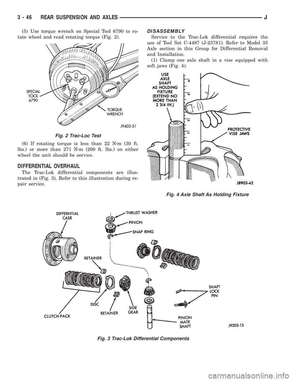
(5) Use torque wrench on Special Tool 6790 to ro-
tate wheel and read rotating torque (Fig. 2).
(6) If rotating torque is less than 22 Nzm (30 ft.
lbs.) or more than 271 Nzm (200 ft. lbs.) on either
wheel the unit should be service.
DIFFERENTIAL OVERHAUL
The Trac-Lok differential components are illus-
trated in (Fig. 3). Refer to this illustration during re-
pair service.
DISASSEMBLY
Service to the Trac-Lok differential requires the
use of Tool Set C-4487 (J-23781). Refer to Model 35
Axle section in this Group for Differential Removal
and Installation.
(1) Clamp one axle shaft in a vise equipped with
soft jaws (Fig. 4).
Fig. 3 Trac-Lok Differential Components
Fig. 2 Trac-Loc Test
Fig. 4 Axle Shaft As Holding Fixture
3 - 46 REAR SUSPENSION AND AXLESJ
Page 149 of 2158
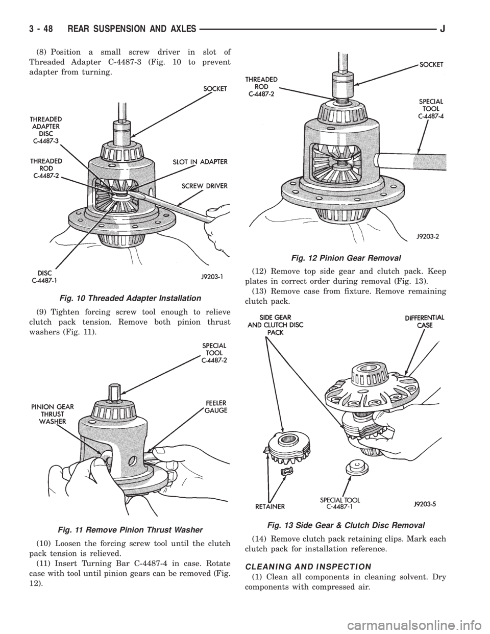
(8) Position a small screw driver in slot of
Threaded Adapter C-4487-3 (Fig. 10 to prevent
adapter from turning.
(9) Tighten forcing screw tool enough to relieve
clutch pack tension. Remove both pinion thrust
washers (Fig. 11).
(10) Loosen the forcing screw tool until the clutch
pack tension is relieved.
(11) Insert Turning Bar C-4487-4 in case. Rotate
case with tool until pinion gears can be removed (Fig.
12).(12) Remove top side gear and clutch pack. Keep
plates in correct order during removal (Fig. 13).
(13) Remove case from fixture. Remove remaining
clutch pack.
(14) Remove clutch pack retaining clips. Mark each
clutch pack for installation reference.
CLEANING AND INSPECTION
(1) Clean all components in cleaning solvent. Dry
components with compressed air.
Fig. 10 Threaded Adapter Installation
Fig. 11 Remove Pinion Thrust Washer
Fig. 12 Pinion Gear Removal
Fig. 13 Side Gear & Clutch Disc Removal
3 - 48 REAR SUSPENSION AND AXLESJ
Page 159 of 2158
fied. This causes pull to switch direction in favor of
the brake unit that is functioning normally.
When diagnosing a change in pull condition, re-
member that pull will return to the original direction
if the dragging brake unit is allowed to cool down
(and is not seriously damaged).
REAR BRAKE GRAB
Rear grab (or pull) is usually caused by contami-
nated lining, bent or binding shoes and support
plates, or improperly assembled components. This is
particularly true when only one rear wheel is in-
volved. However, when both rear wheels are affected,
the master cylinder could be at fault.
BRAKES DO NOT HOLD AFTER DRIVING THROUGH
DEEP WATER PUDDLES
This condition is caused by water soaked lining. If
the lining is only wet, it can be dried by driving with
the brakes lightly applied for a mile or two. However,
if the lining is both wet and dirty, disassembly and
cleaning will be necessary.
CONTAMINATED BRAKELINING
Brakelining contaminated by water is salvageable.
The lining can either be air dried or dried using heat.
In cases where brakelining is contaminated by oil,
grease, or brake fluid, the lining should be replaced.
Replacement is especially necessary when fluids/lu-
bricants have actually soaked into the lining mate-
rial. However, grease or dirt that gets onto the lining
surface (from handling) during brake repairs, can be
cleaned off. Spray the lining surface clean with Mo-
par brake cleaner.
BRAKE FLUID CONTAMINATION
There are two basic causes of brake fluid contami-
nation. The first involves allowing dirt, debris, or
other materials to enter the cylinder reservoirs when
the cover is off. The second involves adding non-rec-
ommended fluids to the cylinder reservoirs.
Brake fluid contaminated with only dirt, or debris
usually retains a normal appearance. In some cases,
the foreign material will remain suspended in the
fluid and be visible. The fluid and foreign material
can be removed from the reservoir with a suction gun
but only if the brakes have not been applied. If the
brakes are applied after contamination, system flush-
ing will be required. The master cylinder may also
have to be disassembled, cleaned and the piston seals
replaced. Foreign material lodged in the reservoir
compensator/return ports can cause brake drag by re-
stricting fluid return after brake application.
Brake fluid contaminated by a non-recommended
fluid may appear discolored, milky, oily looking, or
foamy. However, remember that brake fluid will
darken in time and occasionally be cloudy in appear-ance. These are normal conditions and should not be
mistaken for contamination.
If some type of oil has been added to the system,
the fluid will separate into distinct layers. To verify
this, drain off a sample with a clean suction gun.
Then pour the sample into a glass container and ob-
serve fluid action. If the fluid separates into distinct
layers, it is definitely contaminated.
The only real correction for contamination by non-
recommended fluid is to flush the entire hydraulic
system and replace all the seals.
BRAKE NOISE
Squeak/Squeal
Factory installed brakelining is made from as-
bestos free materials. These materials have dif-
ferent operating characteristics than previous
lining material. Under certain conditions, as-
bestos free lining may generate some squeak,
groan or chirp noise. This noise is considered
normal and does not indicate a problem. The
only time inspection is necessary, is when noise
becomes constant or when grinding, scraping
noises occur.
Constant brake squeak or squeal may be due to lin-
ings that are wet or contaminated with brake fluid,
grease, or oil. Glazed linings, rotors/drums with hard
spots, and dirt/foreign material embedded in the
brake lining also cause squeak. Loud squeak, squeal,
scraping, or grinding sounds are a sign of severely
worn brake lining. If the lining has worn completely
through in spots, metal-to-metal contact occurs.
Thump/Clunk
Thumping or clunk noises during braking are fre-
quentlynotcaused by brake components. In many
cases, such noises are caused by loose or damaged
steering, suspension, or engine components. However,
calipers that bind on the slide surfaces can generate
a thump or clunk noise. In addition, worn out, im-
properly adjusted, or improperly assembled rear
brakeshoes can also produce a thump noise.
Chatter/Shudder
Brake chatter, or shudder is usually caused by
loose or worn components, or glazed/burnt lining. Ro-
tors with hard spots can also contribute to chatter.
Additional causes of chatter are out of tolerance ro-
tors, brake lining not securely attached to the shoes,
loose wheel bearings and contaminated brake lining.
WHEEL AND TIRE PROBLEMS
Some conditions attributed to brake components
may actually be caused by a wheel or tire problem.
A damaged wheel can cause shudder, vibration and
pull. A worn or damaged tire can also cause pull.
Severely worn tires with very little tread left can
JSERVICE BRAKE DIAGNOSIS 5 - 7