1995 JEEP YJ light
[x] Cancel search: lightPage 71 of 2158

Axle shaft bearings produce noise and vibration
when worn or damaged. The noise generally changes
when the bearings are loaded. Road test the vehicle.
Turn the vehicle sharply to the left and to the right.
This will load the bearings and change the noise
level. Where axle bearing damage is slight, the noise
is usually not noticeable at speeds above 30 mph.
LOW SPEED KNOCK
Low speed knock is generally caused by a worn U-
joint or by worn side-gear thrust washers. A worn
pinion gear shaft bore will also cause low speed
knock.
VIBRATION
Vibration at the rear of the vehicle is usually
caused by a:
²Damaged drive shaft
²Missing drive shaft balance weight
²Worn, out-of-balance wheels
²Loose wheel lug nuts
²Worn U-joint
²Loose spring U-bolts
²Loose/broken springs
²Damaged axle shaft bearings
²Loose pinion gear nut
²Excessive pinion yoke run out²Bent axle shaft
Check for loose or damaged front-end components
or engine/transmission mounts. These components
can contribute to what appears to be a rear-end vi-
bration. Do not overlook engine accessories, brackets
and drive belts.
All driveline components should be examined be-
fore starting any repair.
Refer to Group 22ÐTires And Wheels for addi-
tional information involving vibration diagnosis.
DRIVELINE SNAP
A snap or clunk noise when the vehicle is shifted
into gear (or the clutch engaged), can be caused by:
²High engine idle speed
²Loose engine/transmission/transfer case mounts
²Worn U-joints
²Loose spring mounts
²Loose pinion gear nut and yoke
²Excessive ring gear backlash
²Excessive differential side gear-to-case clearance
The source of a snap or a clunk noise can be deter-
mined with the assistance of a helper. Raise the ve-
hicle on a hoist with the wheels free to rotate.
Instruct the helper to shift the transmission into
gear. Listen for the noise, a mechanics stethoscope is
helpful in isolating the source of a noise.
JFRONT SUSPENSION AND AXLE 2 - 19
Page 75 of 2158

CAUTION: If axle is submerged in water, lubricant
must be replaced immediately to avoid possible
premature axle failure.
LUBRICANT CHANGE
The gear lubricant will drain quicker if the vehicle
has been recently driven.
(1) Raise and support the vehicle.
(2) Remove the lubricant fill hole plug from the dif-
ferential housing cover.
(3) Remove the differential housing cover and
drain the lubricant from the housing.
(4) Clean the housing cavity with a flushing oil,
light engine oil or lint free cloth.Do not use water,
steam, kerosene or gasoline for cleaning.
(5) Remove the sealant from the housing and cover
surfaces. Use solvent to clean the mating surfaces.
(6) Apply a bead of MOPARtSilicone Rubber Seal-
ant to the housing cover (Fig. 1).Allow the sealant
to cure for a few minutes.
Install the housing cover within 5 minutes af-
ter applying the sealant. If not installed the
sealant must be removed and another bead ap-
plied.
(7) Install the cover and any identification tag.
Tighten the cover bolts in a criss-cross pattern to 41
Nzm (30 ft. lbs.) torque.
(8) Refill the differential with MOPARtHypoid
Gear Lubricant to bottom of the fill plug hole.
(9) Install the fill hole plug and lower the vehicle.
DRIVE AXLE ASSEMBLY REPLACEMENTÐXJ
VEHICLES
REMOVAL
(1) Raise the vehicle and position support stands
under the frame rails behind the lower suspension
arm frame brackets.
(2) Remove the front wheels.
(3) Remove the brake components and ABS brake
sensor (if equipped). Refer to Group 5ÐBrakes.
(4) On 4WD vehicles, disconnect the axle vent
hose.
(5) On 4WD vehicles, mark the drive shaft yoke
and axle pinion yoke for alignment reference. Discon-
nect the drive shaft from the axle.
(6) Disconnect the stabilizer bar link at the axle
bracket.
(7) Disconnect the shock absorbers from axle
bracket.
(8) Disconnect the track bar from the axle bracket.
(9) Disconnect the tie rod and drag link from the
steering knuckle. Disconnect the steering damper
from the axle bracket.
(10) Support the axle with a hydraulic jack under
the differential.
(11) Disconnect the upper and lower suspension
arms from the axle bracket.
(12) Lower the jack enough to remove the axle.
The coil springs will drop with the axle.
(13) Remove the coil springs from the axle bracket.
INSTALLATION
CAUTION: Suspension components with rubber
bushings should be tightened with the vehicle at
normal height. It is important to have the springs
supporting the weight of the vehicle when the fas-
teners are torqued. If springs are not at their normal
ride position, vehicle ride comfort could be affected
and premature bushing wear may occur. Rubber
bushings must never be lubricated.
(1) Install the springs and retainer clip. Tighten
the retainer bolts to 21 Nzm (16 ft. lbs.) torque.
(2) Support the axle on a hydraulic jack under the
differential. Position the axle under the vehicle.
(3) Raise the axle with a floor jack and align it
with the spring pads.
(4) Position the upper and lower suspension arm at
the axle bracket. Install bolts and nuts finger
tighten.
(5) Connect the track bar to the axle bracket and
install the bolt.Do not tighten at this time.
It is important that the springs support the
weight of the vehicle when the track bar is con-
nected. If springs are not at their usual posi-
tion, vehicle ride comfort could be affected.
Fig. 1 Typical Housing Cover With Sealant
JFRONT SUSPENSION AND AXLE 2 - 23
Page 77 of 2158
(17) Tighten the track bar nut at the axle bracket
to 100 Nzm (74 ft. lbs.) torque.
(18) Check the front wheel alignment.
PINION SEAL REPLACEMENT
REMOVAL
(1) Raise and support the vehicle.
(2) Remove wheel and tire assemblies.
(3) Mark the propeller shaft yoke and pinion yoke
for installation alignment reference.
(4) Remove the propeller shaft from the yoke.
(5) Remove the pinion yoke nut and washer. Use
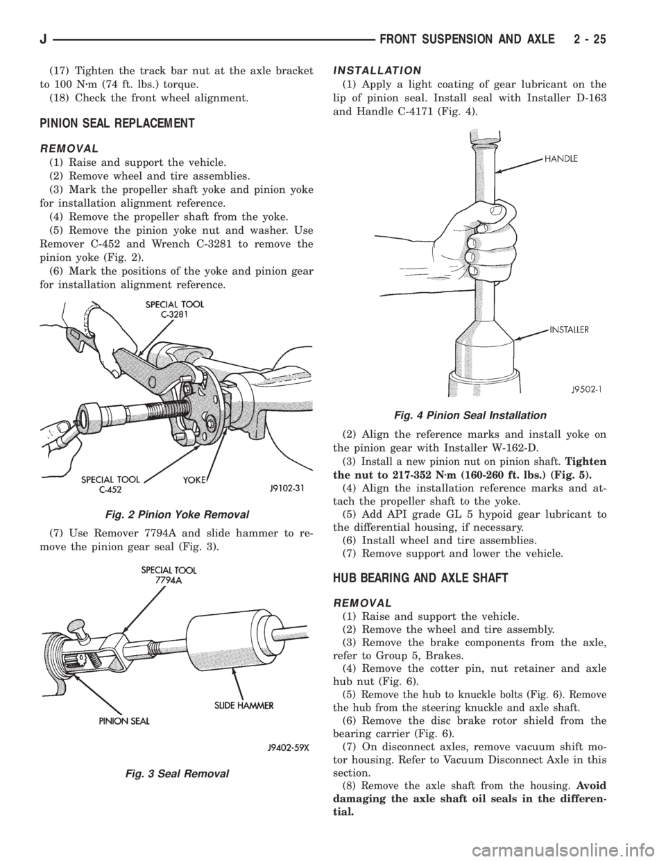
Remover C-452 and Wrench C-3281 to remove the
pinion yoke (Fig. 2).
(6) Mark the positions of the yoke and pinion gear
for installation alignment reference.
(7) Use Remover 7794A and slide hammer to re-
move the pinion gear seal (Fig. 3).
INSTALLATION
(1) Apply a light coating of gear lubricant on the
lip of pinion seal. Install seal with Installer D-163
and Handle C-4171 (Fig. 4).
(2) Align the reference marks and install yoke on
the pinion gear with Installer W-162-D.
(3) Install a new pinion nut on pinion shaft.Tighten
the nut to 217-352 Nzm (160-260 ft. lbs.) (Fig. 5).
(4) Align the installation reference marks and at-
tach the propeller shaft to the yoke.
(5) Add API grade GL 5 hypoid gear lubricant to
the differential housing, if necessary.
(6) Install wheel and tire assemblies.
(7) Remove support and lower the vehicle.
HUB BEARING AND AXLE SHAFT
REMOVAL
(1) Raise and support the vehicle.
(2) Remove the wheel and tire assembly.
(3) Remove the brake components from the axle,
refer to Group 5, Brakes.
(4) Remove the cotter pin, nut retainer and axle
hub nut (Fig. 6).
(5) Remove the hub to knuckle bolts (Fig. 6). Remove
the hub from the steering knuckle and axle shaft.
(6) Remove the disc brake rotor shield from the
bearing carrier (Fig. 6).
(7) On disconnect axles, remove vacuum shift mo-
tor housing. Refer to Vacuum Disconnect Axle in this
section.
(8) Remove the axle shaft from the housing.Avoid
damaging the axle shaft oil seals in the differen-
tial.
Fig. 2 Pinion Yoke Removal
Fig. 3 Seal Removal
Fig. 4 Pinion Seal Installation
JFRONT SUSPENSION AND AXLE 2 - 25
Page 83 of 2158
SHIFT MOTORÐREMOVAL/DISASSEMBLY
(1) Disconnect the vacuum and wiring connector
from the shift housing.
(2) Remove indicator switch.
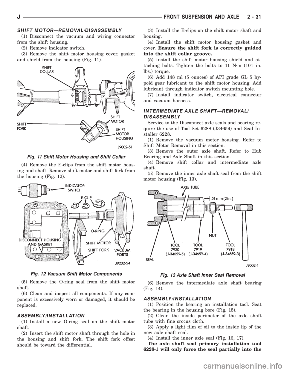
(3) Remove the shift motor housing cover, gasket
and shield from the housing (Fig. 11).
(4) Remove the E-clips from the shift motor hous-
ing and shaft. Remove shift motor and shift fork from
the housing (Fig. 12).
(5) Remove the O-ring seal from the shift motor
shaft.
(6) Clean and inspect all components. If any com-
ponent is excessively worn or damaged, it should be
replaced.
ASSEMBLY/INSTALLATION
(1) Install a new O-ring seal on the shift motor
shaft.
(2) Insert the shift motor shaft through the hole in
the housing and shift fork. The shift fork offset
should be toward the differential.(3) Install the E-clips on the shift motor shaft and
housing.
(4) Install the shift motor housing gasket and
cover.Ensure the shift fork is correctly guided
into the shift collar groove.
(5) Install the shift motor housing shield and at-
taching bolts. Tighten the bolts to 11 Nzm (101 in.
lbs.) torque.
(6) Add 148 ml (5 ounces) of API grade GL 5 hy-
poid gear lubricant to the shift motor housing. Add
lubricant through indicator switch mounting hole.
(7) Install indicator switch, electrical connector
and vacuum harness.
INTERMEDIATE AXLE SHAFTÐREMOVAL/
DISASSEMBLY
Service to the Disconnect axle seals and bearing re-
quire the use of Tool Set 6288 (J34659) and Seal In-
staller 6228.
(1) Remove the vacuum motor housing. Refer to
Shift Motor Removal in this section.
(3) Remove the outer axle shaft. Refer to Hub
Bearing and Axle Shaft in this section.
(4) Remove shift collar and intermediate axle
shaft.
(5) Remove the inner axle shaft seal from the shift
motor housing (Fig. 13).
(6) Remove the intermediate axle shaft bearing
(Fig. 14).
ASSEMBLY/INSTALLATION
(1) Position the bearing on installation tool. Seat
the bearing in the housing bore (Fig. 15).
(2) Clean the inside perimeter of the axle shaft
tube with fine crocus cloth.
(3) Apply a light film of oil to the inside lip of the
new axle shaft seal.
(4) Install the inner axle seal (Fig. 16, 17).
The axle shaft seal primary installation tool
6228-1 will only force the seal partially into the
Fig. 11 Shift Motor Housing and Shift Collar
Fig. 12 Vacuum Shift Motor ComponentsFig. 13 Axle Shaft Inner Seal Removal
JFRONT SUSPENSION AND AXLE 2 - 31
Page 94 of 2158
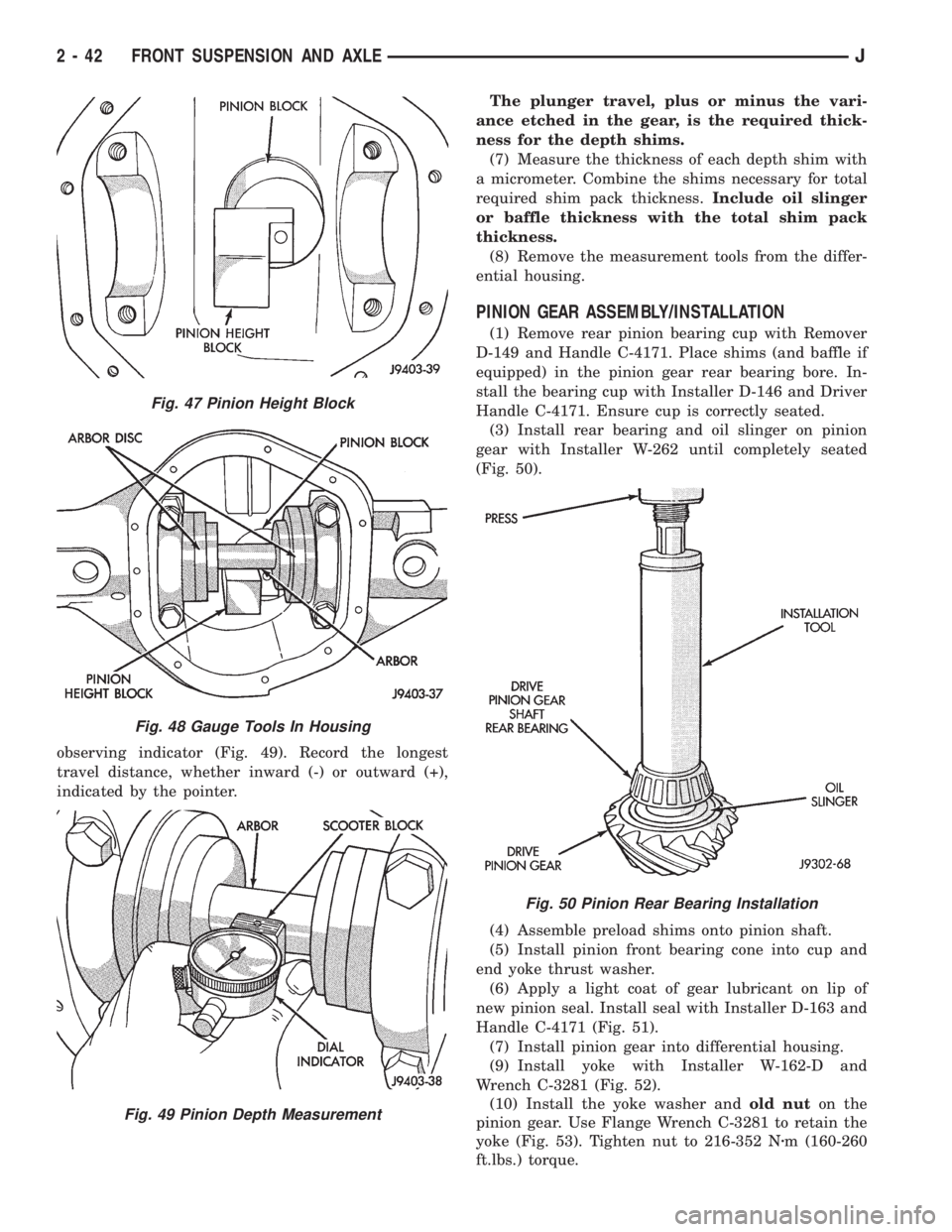
observing indicator (Fig. 49). Record the longest
travel distance, whether inward (-) or outward (+),
indicated by the pointer.The plunger travel, plus or minus the vari-
ance etched in the gear, is the required thick-
ness for the depth shims.
(7) Measure the thickness of each depth shim with
a micrometer. Combine the shims necessary for total
required shim pack thickness.Include oil slinger
or baffle thickness with the total shim pack
thickness.
(8) Remove the measurement tools from the differ-
ential housing.
PINION GEAR ASSEMBLY/INSTALLATION
(1) Remove rear pinion bearing cup with Remover
D-149 and Handle C-4171. Place shims (and baffle if
equipped) in the pinion gear rear bearing bore. In-
stall the bearing cup with Installer D-146 and Driver
Handle C-4171. Ensure cup is correctly seated.
(3) Install rear bearing and oil slinger on pinion
gear with Installer W-262 until completely seated
(Fig. 50).
(4) Assemble preload shims onto pinion shaft.
(5) Install pinion front bearing cone into cup and
end yoke thrust washer.
(6) Apply a light coat of gear lubricant on lip of
new pinion seal. Install seal with Installer D-163 and
Handle C-4171 (Fig. 51).
(7) Install pinion gear into differential housing.
(9) Install yoke with Installer W-162-D and
Wrench C-3281 (Fig. 52).
(10) Install the yoke washer andold nuton the
pinion gear. Use Flange Wrench C-3281 to retain the
yoke (Fig. 53). Tighten nut to 216-352 Nzm (160-260
ft.lbs.) torque.
Fig. 47 Pinion Height Block
Fig. 48 Gauge Tools In Housing
Fig. 49 Pinion Depth Measurement
Fig. 50 Pinion Rear Bearing Installation
2 - 42 FRONT SUSPENSION AND AXLEJ
Page 106 of 2158
LEAF SPRING EYE BUSHING REPLACEMENT
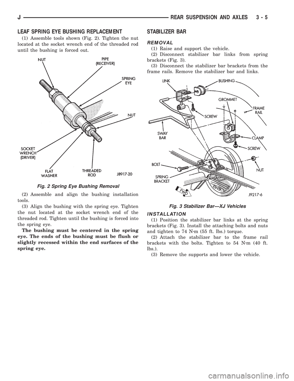
(1) Assemble tools shown (Fig. 2). Tighten the nut
located at the socket wrench end of the threaded rod
until the bushing is forced out.
(2) Assemble and align the bushing installation
tools.
(3) Align the bushing with the spring eye. Tighten
the nut located at the socket wrench end of the
threaded rod. Tighten until the bushing is forced into
the spring eye.
The bushing must be centered in the spring
eye. The ends of the bushing must be flush or
slightly recessed within the end surfaces of the
spring eye.
STABILIZER BAR
REMOVAL
(1) Raise and support the vehicle.
(2) Disconnect stabilizer bar links from spring
brackets (Fig. 3).
(3) Disconnect the stabilizer bar brackets from the
frame rails. Remove the stabilizer bar and links.
INSTALLATION
(1) Position the stabilizer bar links at the spring
brackets (Fig. 3). Install the attaching bolts and nuts
and tighten to 74 Nzm (55 ft. lbs.) torque.
(2) Attach the stabilizer bar to the frame rail
brackets with the bolts. Tighten to 54 Nzm (40 ft.
lbs.).
(3) Remove the supports and lower the vehicle.
Fig. 2 Spring Eye Bushing Removal
Fig. 3 Stabilizer BarÐXJ Vehicles
JREAR SUSPENSION AND AXLES 3 - 5
Page 109 of 2158
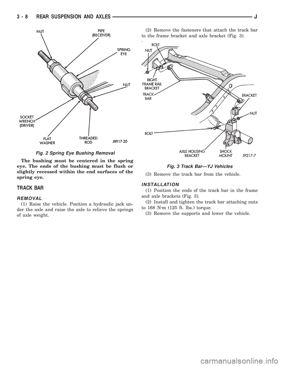
The bushing must be centered in the spring
eye. The ends of the bushing must be flush or
slightly recessed within the end surfaces of the
spring eye.
TRACK BAR
REMOVAL
(1) Raise the vehicle. Position a hydraulic jack un-
der the axle and raise the axle to relieve the springs
of axle weight.(2) Remove the fasteners that attach the track bar
to the frame bracket and axle bracket (Fig. 3).
(3) Remove the track bar from the vehicle.
INSTALLATION
(1) Position the ends of the track bar in the frame
and axle brackets (Fig. 3).
(2) Install and tighten the track bar attaching nuts
to 168 Nzm (125 ft. lbs.) torque.
(3) Remove the supports and lower the vehicle.
Fig. 2 Spring Eye Bushing Removal
Fig. 3 Track BarÐYJ Vehicles
3 - 8 REAR SUSPENSION AND AXLESJ
Page 111 of 2158

This will load the bearings and change the noise
level. Where axle bearing damage is slight, the noise
is usually not noticeable at speeds above 30 mph.
LOW SPEED KNOCK
Low speed knock is generally caused by a worn
U-joint or by worn side-gear thrust washers. A worn
pinion gear shaft bore will also cause low speed knock.
VIBRATION
Vibration at the rear of the vehicle is usually
caused by a:
²Damaged drive shaft
²Missing drive shaft balance weight
²Worn, out-of-balance wheels
²Loose wheel lug nuts
²Worn U-joint
²Loose spring U-bolts
²Loose/broken springs
²Damaged axle shaft bearings
²Loose pinion gear nut
²Excessive pinion yoke run out
²Bent axle shaft
Check for loose or damaged front-end components
or engine/transmission mounts. These components
can contribute to what appears to be a rear-end vi-
bration. Do not overlook engine accessories, brackets
and drive belts.
All driveline components should be examined be-
fore starting any repair.
Refer to Group 22, Wheels and Tires for additional
information.
DRIVELINE SNAP
A snap or clunk noise when the vehicle is shifted
into gear (or the clutch engaged), can be caused by:
²High engine idle speed
²Loose engine/transmission/transfer case mounts
²Worn U-joints
²Loose spring mounts
²Loose pinion gear nut and yoke
²Excessive ring gear backlash
²Excessive side gear\ase clearance
The source of a snap or a clunk noise can be deter-
mined with the assistance of a helper. Raise the ve-
hicle on a hoist with the wheels free to rotate.
Instruct the helper to shift the transmission into
gear. Listen for the noise, a mechanics stethoscope is
helpful in isolating the source of a noise.
REAR AXLE ALIGNMENT
MEASUREMENT
The following procedure can be used to determine
if abnormal rear tire tread wear is the result of a
bent or deformed rear axle shaft.
(1) Raise both rear wheels off the surface with a
frame contact hoist.
(2) Attach a one-inch long piece of masking tape at
the center of each tire tread for use as reference marks.
(3) Rotate the rear wheels until both reference
marks face the front of the vehicle. Measure the dis-
tance between the outside edges of the two pieces of
tape. Record this measurement as the front of tire
(FTR) measurement.
(4) Rotate the rear wheels until both reference
marks face the rear of the vehicle. Measure the dis-
tance between the outside edges of the two pieces of
tape. Record this measurement as the rear of tire
(RTR) measurement.
(5) Subtract the (RTR) measurement from the
(FTR) measurement to obtain the amount of wheel
toe. The acceptable rear wheel toe-in position is 1/16
inch (1.6 mm) to 3/16 inch (4.8 mm) toe-out.
(6) Rotate the rear wheels until the reference
marks are facing downward. Measure the distance
between the outside edges of the two pieces of tape.
Record this measurement as the bottom of tire (BTR)
measurement.
(7) Average the (FTR) and the (RTR) distance mea-
surements. Subtract the (BTR) measurement from
this average distance to obtain the camber. The ac-
ceptable amount of camber is 1/16 inch to 3/32 inch
(1.6 to 2.4 mm).
(FTR + RTR) DIVIDED BY 2 (TWO) MINUS
BTR EQUALS CAMBER
If the (BTR) distance measurement is less
than the average FTR and RTR distance mea-
surement, the camber will be positive(+).If
the (BTR) distance measurement is greater
than the average FTR and RTR distance, the
camber will be negative(-).
If the toe position or camber is not acceptable, a bent
or deformed rear axle shaft is most likely the cause.
LIMITED SLIP DIFFERENTIAL
Under normal traction conditions, engine torque is di-
vided evenly. With low-traction surfaces, engine torque
is transferred to the wheel with the most tire traction.
When diagnosing a limited-slip differential the wheel
with the least traction can continue spinning.
The most common problem is a chatter noise when
turning corners. Check for incorrect or contaminated
lubricant. Replace the gear lubricant if necessary.
²With Trac-LokŸ differentials add a container of
MOPAR Trac-Lok Lubricant.
This will correct the condition in most instances. If
the chatter persists, clutch damage could have oc-
curred.
After changing the lubricant, drive the vehicle and
make 10 to 12 slow, figure-eight turns. This maneu-
ver will pump lubricant through the clutches.
3 - 10 REAR SUSPENSION AND AXLESJ