1995 JEEP YJ flat tire
[x] Cancel search: flat tirePage 1282 of 2158
CAUTION: DO NOT use engine or transmission oil,
mineral spirits or kerosene.
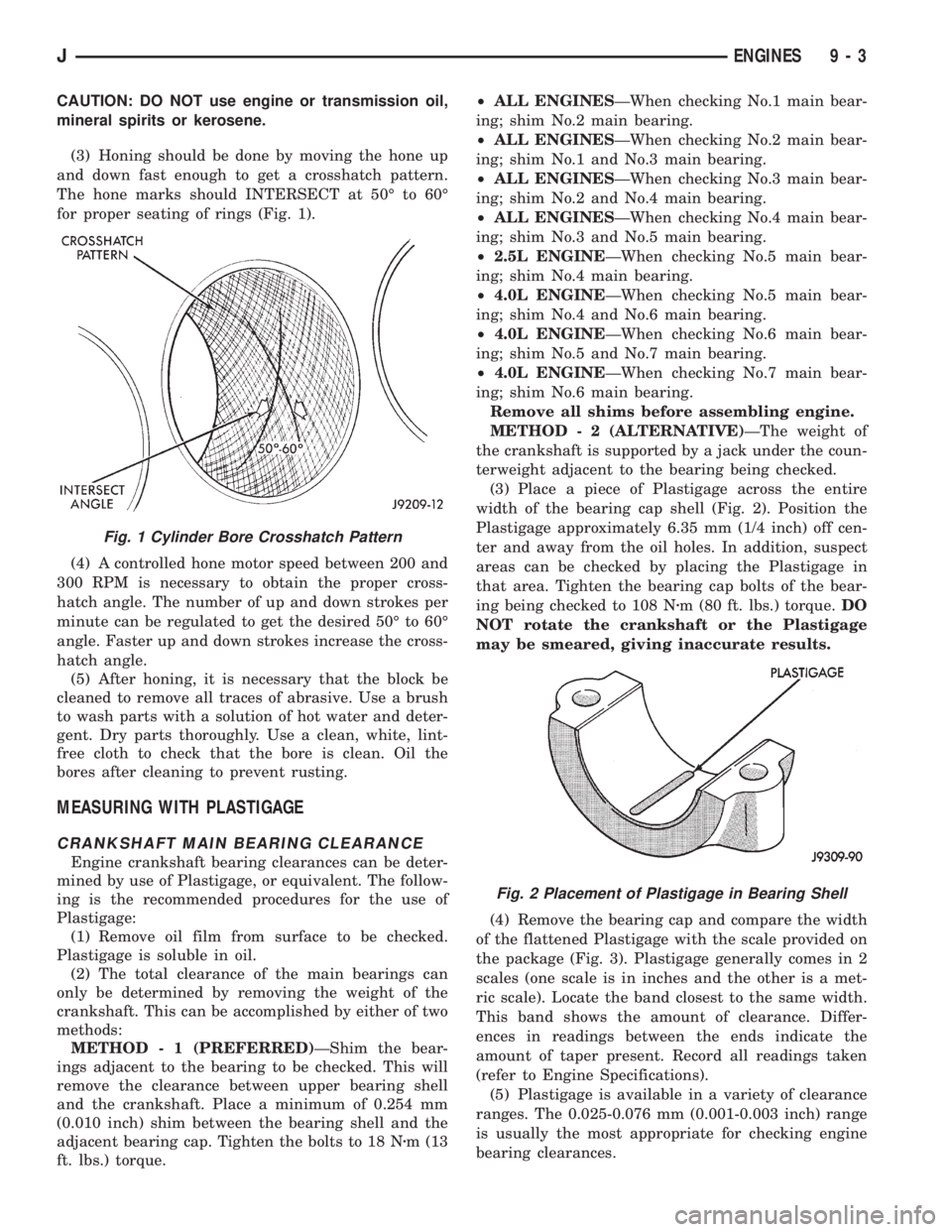
(3) Honing should be done by moving the hone up
and down fast enough to get a crosshatch pattern.
The hone marks should INTERSECT at 50É to 60É
for proper seating of rings (Fig. 1).
(4) A controlled hone motor speed between 200 and
300 RPM is necessary to obtain the proper cross-
hatch angle. The number of up and down strokes per
minute can be regulated to get the desired 50É to 60É
angle. Faster up and down strokes increase the cross-
hatch angle.
(5) After honing, it is necessary that the block be
cleaned to remove all traces of abrasive. Use a brush
to wash parts with a solution of hot water and deter-
gent. Dry parts thoroughly. Use a clean, white, lint-
free cloth to check that the bore is clean. Oil the
bores after cleaning to prevent rusting.
MEASURING WITH PLASTIGAGE
CRANKSHAFT MAIN BEARING CLEARANCE
Engine crankshaft bearing clearances can be deter-
mined by use of Plastigage, or equivalent. The follow-
ing is the recommended procedures for the use of
Plastigage:
(1) Remove oil film from surface to be checked.
Plastigage is soluble in oil.
(2) The total clearance of the main bearings can
only be determined by removing the weight of the
crankshaft. This can be accomplished by either of two
methods:
METHOD - 1 (PREFERRED)ÐShim the bear-
ings adjacent to the bearing to be checked. This will
remove the clearance between upper bearing shell
and the crankshaft. Place a minimum of 0.254 mm
(0.010 inch) shim between the bearing shell and the
adjacent bearing cap. Tighten the bolts to 18 Nzm (13
ft. lbs.) torque.²ALL ENGINESÐWhen checking No.1 main bear-
ing; shim No.2 main bearing.
²ALL ENGINESÐWhen checking No.2 main bear-
ing; shim No.1 and No.3 main bearing.
²ALL ENGINESÐWhen checking No.3 main bear-
ing; shim No.2 and No.4 main bearing.
²ALL ENGINESÐWhen checking No.4 main bear-
ing; shim No.3 and No.5 main bearing.
²2.5L ENGINEÐWhen checking No.5 main bear-
ing; shim No.4 main bearing.
²4.0L ENGINEÐWhen checking No.5 main bear-
ing; shim No.4 and No.6 main bearing.
²4.0L ENGINEÐWhen checking No.6 main bear-
ing; shim No.5 and No.7 main bearing.
²4.0L ENGINEÐWhen checking No.7 main bear-
ing; shim No.6 main bearing.
Remove all shims before assembling engine.
METHOD - 2 (ALTERNATIVE)ÐThe weight of
the crankshaft is supported by a jack under the coun-
terweight adjacent to the bearing being checked.
(3) Place a piece of Plastigage across the entire
width of the bearing cap shell (Fig. 2). Position the
Plastigage approximately 6.35 mm (1/4 inch) off cen-
ter and away from the oil holes. In addition, suspect
areas can be checked by placing the Plastigage in
that area. Tighten the bearing cap bolts of the bear-
ing being checked to 108 Nzm (80 ft. lbs.) torque.DO
NOT rotate the crankshaft or the Plastigage
may be smeared, giving inaccurate results.
(4) Remove the bearing cap and compare the width
of the flattened Plastigage with the scale provided on
the package (Fig. 3). Plastigage generally comes in 2
scales (one scale is in inches and the other is a met-
ric scale). Locate the band closest to the same width.
This band shows the amount of clearance. Differ-
ences in readings between the ends indicate the
amount of taper present. Record all readings taken
(refer to Engine Specifications).
(5) Plastigage is available in a variety of clearance
ranges. The 0.025-0.076 mm (0.001-0.003 inch) range
is usually the most appropriate for checking engine
bearing clearances.
Fig. 1 Cylinder Bore Crosshatch Pattern
Fig. 2 Placement of Plastigage in Bearing Shell
JENGINES 9 - 3
Page 1283 of 2158
CONNECTING ROD BEARING CLEARANCE
Engine connecting rod bearing clearances can be
determined by use of Plastigage, or equivalent. The
following is the recommended procedures for the use
of Plastigage:
(1) Remove oil film from surface to be checked.
Plastigage is soluble in oil.
(2) Place a piece of Plastigage across the entire width
of the bearing cap shell (Fig. 2). Position the Plastigage
approximately 6.35 mm (1/4 inch) off center and away
from the oil holes. In addition, suspect areas can be
checked by placing the Plastigage in the suspect area.
(3) The crankshaft must be turned until the connect-
ing rod to be checked starts moving toward the top of
the engine. Only then should the rod cap with Plasti-
gage in place be assembled. Tighten the rod cap nut to
45 Nzm (33 ft. lbs.) torque.DO NOT rotate the crank-
shaft or the Plastigage may be smeared, giving in-
accurate results.
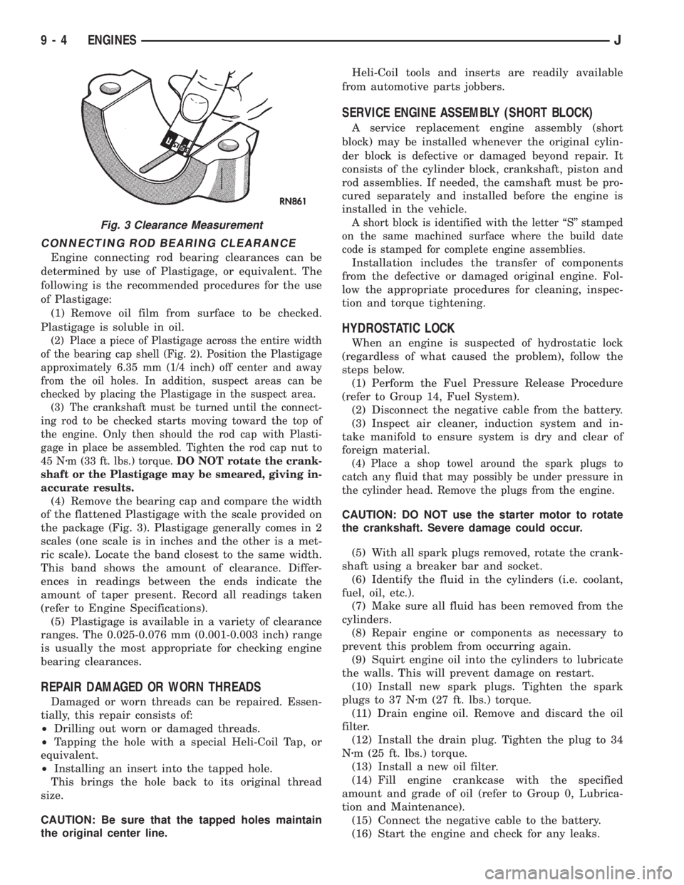
(4) Remove the bearing cap and compare the width
of the flattened Plastigage with the scale provided on
the package (Fig. 3). Plastigage generally comes in 2
scales (one scale is in inches and the other is a met-
ric scale). Locate the band closest to the same width.
This band shows the amount of clearance. Differ-
ences in readings between the ends indicate the
amount of taper present. Record all readings taken
(refer to Engine Specifications).
(5) Plastigage is available in a variety of clearance
ranges. The 0.025-0.076 mm (0.001-0.003 inch) range
is usually the most appropriate for checking engine
bearing clearances.
REPAIR DAMAGED OR WORN THREADS
Damaged or worn threads can be repaired. Essen-
tially, this repair consists of:
²Drilling out worn or damaged threads.
²Tapping the hole with a special Heli-Coil Tap, or
equivalent.
²Installing an insert into the tapped hole.
This brings the hole back to its original thread
size.
CAUTION: Be sure that the tapped holes maintain
the original center line.Heli-Coil tools and inserts are readily available
from automotive parts jobbers.
SERVICE ENGINE ASSEMBLY (SHORT BLOCK)
A service replacement engine assembly (short
block) may be installed whenever the original cylin-
der block is defective or damaged beyond repair. It
consists of the cylinder block, crankshaft, piston and
rod assemblies. If needed, the camshaft must be pro-
cured separately and installed before the engine is
installed in the vehicle.
A short block is identified with the letter ``S'' stamped
on the same machined surface where the build date
code is stamped for complete engine assemblies.
Installation includes the transfer of components
from the defective or damaged original engine. Fol-
low the appropriate procedures for cleaning, inspec-
tion and torque tightening.
HYDROSTATIC LOCK
When an engine is suspected of hydrostatic lock
(regardless of what caused the problem), follow the
steps below.
(1) Perform the Fuel Pressure Release Procedure
(refer to Group 14, Fuel System).
(2) Disconnect the negative cable from the battery.
(3) Inspect air cleaner, induction system and in-
take manifold to ensure system is dry and clear of
foreign material.
(4) Place a shop towel around the spark plugs to
catch any fluid that may possibly be under pressure in
the cylinder head. Remove the plugs from the engine.
CAUTION: DO NOT use the starter motor to rotate
the crankshaft. Severe damage could occur.
(5) With all spark plugs removed, rotate the crank-
shaft using a breaker bar and socket.
(6) Identify the fluid in the cylinders (i.e. coolant,
fuel, oil, etc.).
(7) Make sure all fluid has been removed from the
cylinders.
(8) Repair engine or components as necessary to
prevent this problem from occurring again.
(9) Squirt engine oil into the cylinders to lubricate
the walls. This will prevent damage on restart.
(10) Install new spark plugs. Tighten the spark
plugs to 37 Nzm (27 ft. lbs.) torque.
(11) Drain engine oil. Remove and discard the oil
filter.
(12) Install the drain plug. Tighten the plug to 34
Nzm (25 ft. lbs.) torque.
(13) Install a new oil filter.
(14) Fill engine crankcase with the specified
amount and grade of oil (refer to Group 0, Lubrica-
tion and Maintenance).
(15) Connect the negative cable to the battery.
(16) Start the engine and check for any leaks.
Fig. 3 Clearance Measurement
9 - 4 ENGINESJ
Page 1474 of 2158
²Have at least a 1/2 degree continuous operating
(propeller shaft) angle
Engine speed (R.P.M.) is the main factor though in
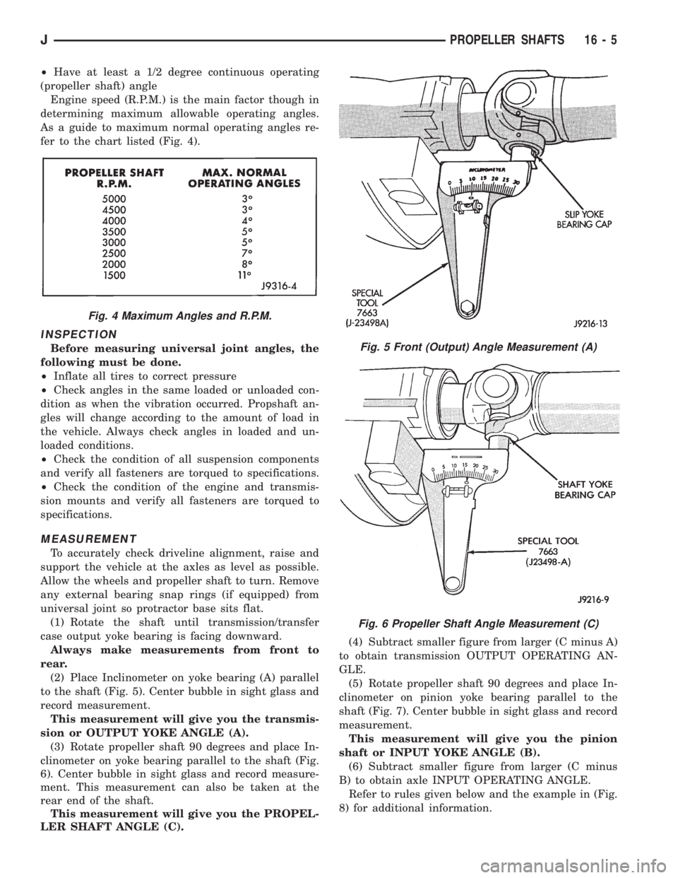
determining maximum allowable operating angles.
As a guide to maximum normal operating angles re-
fer to the chart listed (Fig. 4).
INSPECTION
Before measuring universal joint angles, the
following must be done.
²Inflate all tires to correct pressure
²Check angles in the same loaded or unloaded con-
dition as when the vibration occurred. Propshaft an-
gles will change according to the amount of load in
the vehicle. Always check angles in loaded and un-
loaded conditions.
²Check the condition of all suspension components
and verify all fasteners are torqued to specifications.
²Check the condition of the engine and transmis-
sion mounts and verify all fasteners are torqued to
specifications.
MEASUREMENT
To accurately check driveline alignment, raise and
support the vehicle at the axles as level as possible.
Allow the wheels and propeller shaft to turn. Remove
any external bearing snap rings (if equipped) from
universal joint so protractor base sits flat.
(1) Rotate the shaft until transmission/transfer
case output yoke bearing is facing downward.
Always make measurements from front to
rear.
(2) Place Inclinometer on yoke bearing (A) parallel
to the shaft (Fig. 5). Center bubble in sight glass and
record measurement.
This measurement will give you the transmis-
sion or OUTPUT YOKE ANGLE (A).
(3) Rotate propeller shaft 90 degrees and place In-
clinometer on yoke bearing parallel to the shaft (Fig.
6). Center bubble in sight glass and record measure-
ment. This measurement can also be taken at the
rear end of the shaft.
This measurement will give you the PROPEL-
LER SHAFT ANGLE (C).(4) Subtract smaller figure from larger (C minus A)
to obtain transmission OUTPUT OPERATING AN-
GLE.
(5) Rotate propeller shaft 90 degrees and place In-
clinometer on pinion yoke bearing parallel to the
shaft (Fig. 7). Center bubble in sight glass and record
measurement.
This measurement will give you the pinion
shaft or INPUT YOKE ANGLE (B).
(6) Subtract smaller figure from larger (C minus
B) to obtain axle INPUT OPERATING ANGLE.
Refer to rules given below and the example in (Fig.
8) for additional information.
Fig. 4 Maximum Angles and R.P.M.
Fig. 5 Front (Output) Angle Measurement (A)
Fig. 6 Propeller Shaft Angle Measurement (C)
JPROPELLER SHAFTS 16 - 5
Page 1702 of 2158
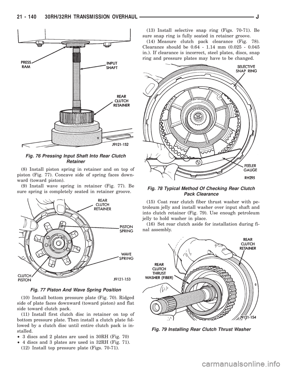
(8) Install piston spring in retainer and on top of
piston (Fig. 77). Concave side of spring faces down-
ward (toward piston).
(9) Install wave spring in retainer (Fig. 77). Be
sure spring is completely seated in retainer groove.
(10) Install bottom pressure plate (Fig. 70). Ridged
side of plate faces downward (toward piston) and flat
side toward clutch pack.
(11) Install first clutch disc in retainer on top of
bottom pressure plate. Then install a clutch plate fol-
lowed by a clutch disc until entire clutch pack is in-
stalled.
²3 discs and 2 plates are used in 30RH (Fig. 70)
²4 discs and 3 plates are used in 32RH (Fig. 71).
(12) Install top pressure plate (Figs. 70-71).(13) Install selective snap ring (Figs. 70-71). Be
sure snap ring is fully seated in retainer groove.
(14) Measure clutch pack clearance (Fig. 78).
Clearance should be 0.64 - 1.14 mm (0.025 - 0.045
in.). If clearance is incorrect, steel plates, discs, snap
ring and pressure plates may have to be changed.
(15) Coat rear clutch fiber thrust washer with pe-
troleum jelly and install washer over input shaft and
into clutch retainer (Fig. 79). Use enough petroleum
jelly to hold washer in place.
(16) Set rear clutch aside for installation during fi-
nal assembly.
Fig. 76 Pressing Input Shaft Into Rear Clutch
Retainer
Fig. 77 Piston And Wave Spring Position
Fig. 78 Typical Method Of Checking Rear Clutch
Pack Clearance
Fig. 79 Installing Rear Clutch Thrust Washer
21 - 140 30RH/32RH TRANSMISSION OVERHAULJ
Page 1907 of 2158
WHEELS AND TIRES
CONTENTS
page page
SPECIFICATIONS........................ 12
TIRES.................................. 1VEHICLE VIBRATION..................... 10
WHEELS................................ 6
TIRES
INDEX
page page
Cleaning of Tires.......................... 2
General Information........................ 1
Pressure Gauges.......................... 2
Repairing Leaks........................... 3
Replacement Tires......................... 2Rotation................................. 3
Tire Inflation Pressures...................... 2
Tire Noise or Vibration...................... 4
Tire Wear Patterns......................... 4
Tread Wear Indicators....................... 3
GENERAL INFORMATION
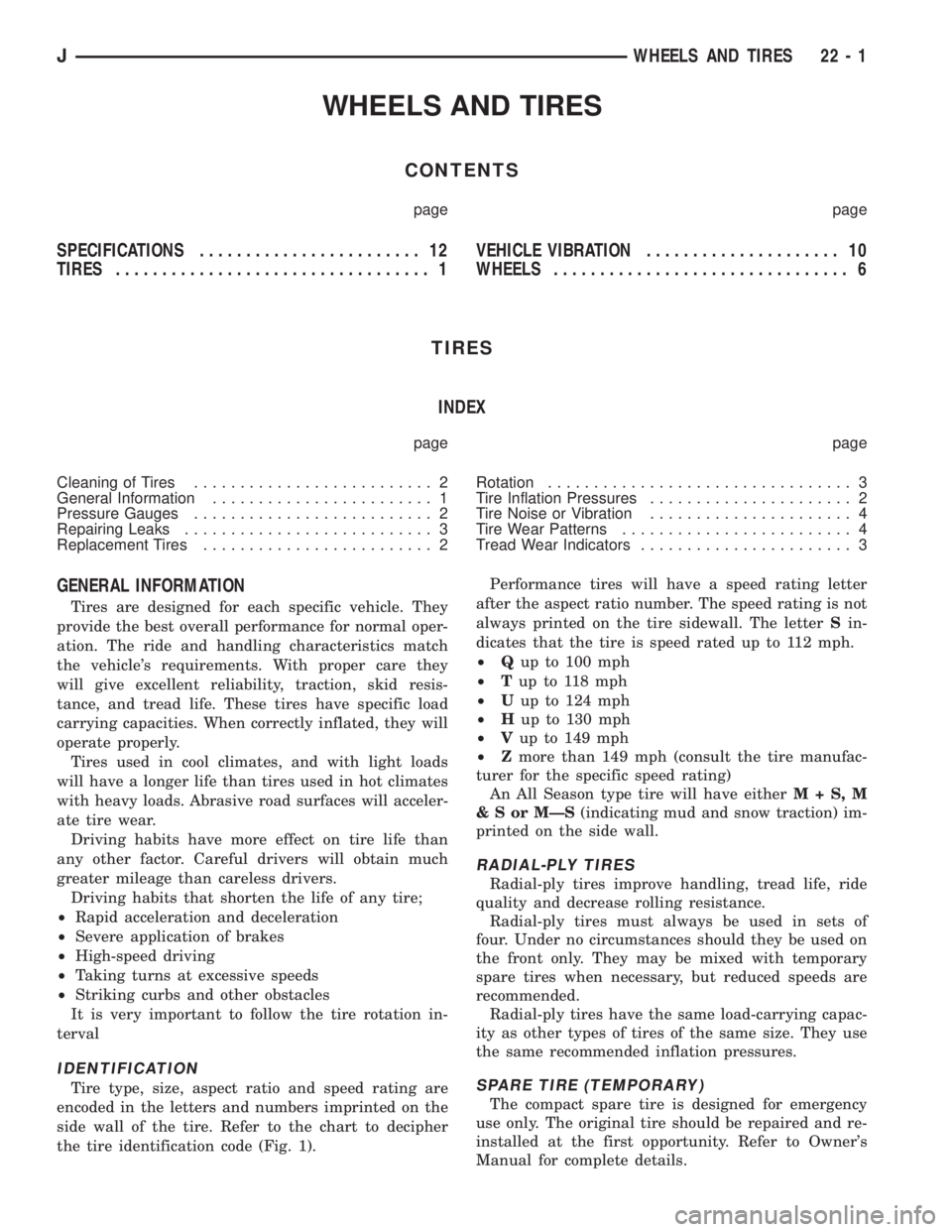
Tires are designed for each specific vehicle. They
provide the best overall performance for normal oper-
ation. The ride and handling characteristics match
the vehicle's requirements. With proper care they
will give excellent reliability, traction, skid resis-
tance, and tread life. These tires have specific load
carrying capacities. When correctly inflated, they will
operate properly.
Tires used in cool climates, and with light loads
will have a longer life than tires used in hot climates
with heavy loads. Abrasive road surfaces will acceler-
ate tire wear.
Driving habits have more effect on tire life than
any other factor. Careful drivers will obtain much
greater mileage than careless drivers.
Driving habits that shorten the life of any tire;
²Rapid acceleration and deceleration
²Severe application of brakes
²High-speed driving
²Taking turns at excessive speeds
²Striking curbs and other obstacles
It is very important to follow the tire rotation in-
terval
IDENTIFICATION
Tire type, size, aspect ratio and speed rating are
encoded in the letters and numbers imprinted on the
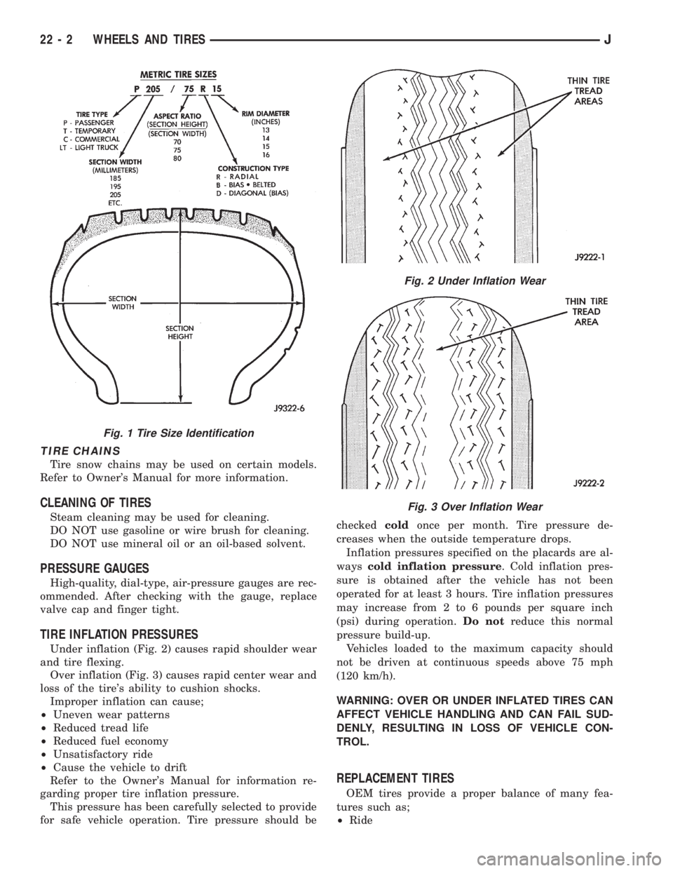
side wall of the tire. Refer to the chart to decipher
the tire identification code (Fig. 1).Performance tires will have a speed rating letter
after the aspect ratio number. The speed rating is not
always printed on the tire sidewall. The letterSin-
dicates that the tire is speed rated up to 112 mph.
²Qup to 100 mph
²Tup to 118 mph
²Uup to 124 mph
²Hup to 130 mph
²Vup to 149 mph
²Zmore than 149 mph (consult the tire manufac-
turer for the specific speed rating)
An All Season type tire will have eitherM+S,M
&SorMÐS(indicating mud and snow traction) im-
printed on the side wall.
RADIAL-PLY TIRES
Radial-ply tires improve handling, tread life, ride
quality and decrease rolling resistance.
Radial-ply tires must always be used in sets of
four. Under no circumstances should they be used on
the front only. They may be mixed with temporary
spare tires when necessary, but reduced speeds are
recommended.
Radial-ply tires have the same load-carrying capac-
ity as other types of tires of the same size. They use
the same recommended inflation pressures.
SPARE TIRE (TEMPORARY)
The compact spare tire is designed for emergency
use only. The original tire should be repaired and re-
installed at the first opportunity. Refer to Owner's
Manual for complete details.
JWHEELS AND TIRES 22 - 1
Page 1908 of 2158
TIRE CHAINS
Tire snow chains may be used on certain models.
Refer to Owner's Manual for more information.
CLEANING OF TIRES
Steam cleaning may be used for cleaning.
DO NOT use gasoline or wire brush for cleaning.
DO NOT use mineral oil or an oil-based solvent.
PRESSURE GAUGES
High-quality, dial-type, air-pressure gauges are rec-
ommended. After checking with the gauge, replace
valve cap and finger tight.
TIRE INFLATION PRESSURES
Under inflation (Fig. 2) causes rapid shoulder wear
and tire flexing.
Over inflation (Fig. 3) causes rapid center wear and
loss of the tire's ability to cushion shocks.
Improper inflation can cause;
²Uneven wear patterns
²Reduced tread life
²Reduced fuel economy
²Unsatisfactory ride
²Cause the vehicle to drift
Refer to the Owner's Manual for information re-
garding proper tire inflation pressure.
This pressure has been carefully selected to provide
for safe vehicle operation. Tire pressure should becheckedcoldonce per month. Tire pressure de-
creases when the outside temperature drops.
Inflation pressures specified on the placards are al-
wayscold inflation pressure. Cold inflation pres-
sure is obtained after the vehicle has not been
operated for at least 3 hours. Tire inflation pressures
may increase from 2 to 6 pounds per square inch
(psi) during operation.Do notreduce this normal
pressure build-up.
Vehicles loaded to the maximum capacity should
not be driven at continuous speeds above 75 mph
(120 km/h).
WARNING: OVER OR UNDER INFLATED TIRES CAN
AFFECT VEHICLE HANDLING AND CAN FAIL SUD-
DENLY, RESULTING IN LOSS OF VEHICLE CON-
TROL.
REPLACEMENT TIRES
OEM tires provide a proper balance of many fea-
tures such as;
²Ride
Fig. 1 Tire Size Identification
Fig. 2 Under Inflation Wear
Fig. 3 Over Inflation Wear
22 - 2 WHEELS AND TIRESJ
Page 1909 of 2158
²Noise
²Handling
²Durability
²Tread life
²Traction
²Rolling resistance
²Speed capability
Original equipment tires should be used when re-
placement is needed.
Refer to the placard on the vehicle or the
Owner's Manual for the correct replacement
tire.
Failure to use original or equivalent replacement
tires may adversely affect the handling of the vehicle.
The use of oversize tiresis not recommended.
They may cause interference with vehicle suspension
and steering travel. This can cause tire damage or
failure.
WARNING: FAILURE TO EQUIP THE VEHICLE WITH
TIRES HAVING ADEQUATE LOAD CAPABILITY CAN
RESULT IN SUDDEN TIRE FAILURE.
ROTATION
Tires on the front and rear axles operate at differ-
ent loads and perform different steering, driving, and
braking functions. For these reasons, the tires wear
at unequal rates. They may also develop irregular
wear patterns. These effects can be reduced by rotat-
ing the tires according to the maintenance schedule
in the Owners Manual. This will improve tread life,
traction and maintain a smooth quiet ride.
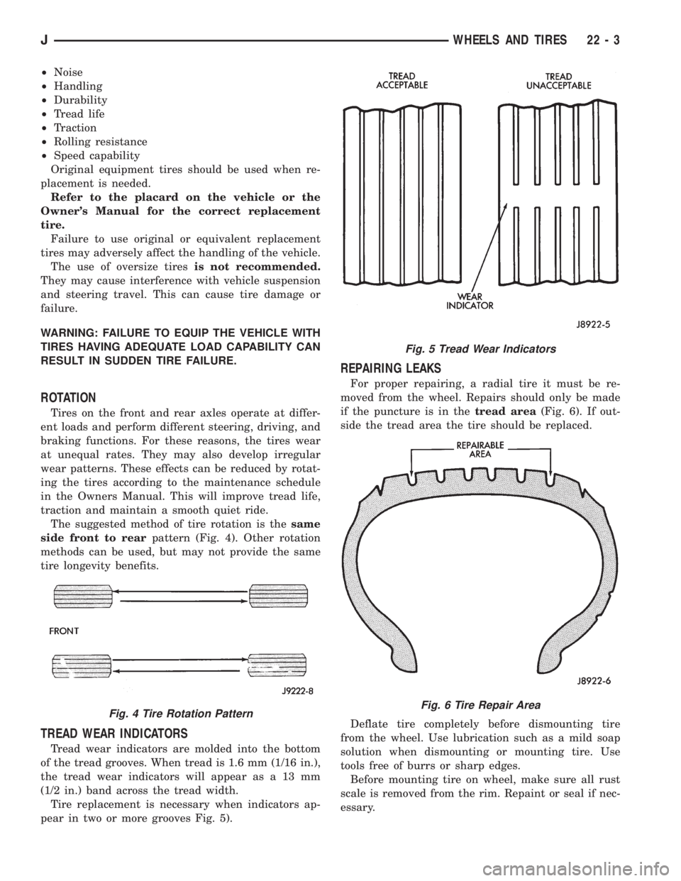
The suggested method of tire rotation is thesame
side front to rearpattern (Fig. 4). Other rotation
methods can be used, but may not provide the same
tire longevity benefits.
TREAD WEAR INDICATORS
Tread wear indicators are molded into the bottom
of the tread grooves. When tread is 1.6 mm (1/16 in.),
the tread wear indicators will appear as a 13 mm
(1/2 in.) band across the tread width.
Tire replacement is necessary when indicators ap-
pear in two or more grooves Fig. 5).
REPAIRING LEAKS
For proper repairing, a radial tire it must be re-
moved from the wheel. Repairs should only be made
if the puncture is in thetread area(Fig. 6). If out-
side the tread area the tire should be replaced.
Deflate tire completely before dismounting tire
from the wheel. Use lubrication such as a mild soap
solution when dismounting or mounting tire. Use
tools free of burrs or sharp edges.
Before mounting tire on wheel, make sure all rust
scale is removed from the rim. Repaint or seal if nec-
essary.
Fig. 4 Tire Rotation Pattern
Fig. 5 Tread Wear Indicators
Fig. 6 Tire Repair Area
JWHEELS AND TIRES 22 - 3
Page 1910 of 2158
TIRE NOISE OR VIBRATION
The radial-ply tire on your vehicle is more sensitive
to improper mounting, or imbalance.
To determine if tires are the cause of vibration,
drive the vehicle over a smooth road at different
speeds. Note the effect of acceleration and decelera-
tion on noise level. Differential and exhaust noise
will change in intensity as speed varies. Tire noise
will usually remain constant.
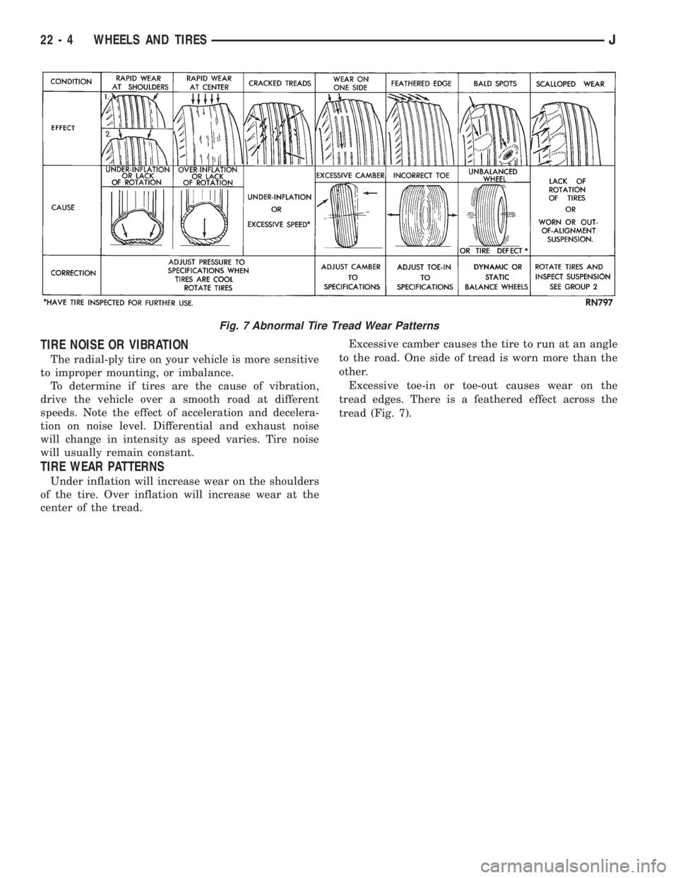
TIRE WEAR PATTERNS
Under inflation will increase wear on the shoulders
of the tire. Over inflation will increase wear at the
center of the tread.Excessive camber causes the tire to run at an angle
to the road. One side of tread is worn more than the
other.
Excessive toe-in or toe-out causes wear on the
tread edges. There is a feathered effect across the
tread (Fig. 7).
Fig. 7 Abnormal Tire Tread Wear Patterns
22 - 4 WHEELS AND TIRESJ