1995 JEEP YJ bolt pattern
[x] Cancel search: bolt patternPage 226 of 2158
when handling the cover and disc. Impact can distort
the cover, diaphragm spring, release fingers and the
hub of the clutch disc.
Use an alignment tool when positioning the disc on
the flywheel. The tool prevents accidental misalign-
ment which could result in cover distortion and disc
damage.
A frequent cause of clutch cover distortion (and
consequent misalignment) is improper bolt tighten-
ing. To avoid warping the cover, the bolts must tight-
ened alternately (diagonal pattern) and evenly (2-3
threads at a time) to specified torque.
CLUTCH HOUSING MISALIGNMENT
Clutch housing alignment is important to proper
clutch operation. The housing maintains alignment
between the crankshaft and transmission input
shaft. Misalignment can cause clutch noise, hard
shifting, incomplete release and chatter. It can also
result in premature wear of the pilot bearing, cover
release fingers and clutch disc. In severe cases, mis-
alignment can also cause premature wear of the
transmission input shaft and front bearing.
Housing misalignment is generally caused by incor-
rect seating on the engine or transmission, loose
housing bolts, missing alignment dowels, or housing
damage. Infrequently, misalignment may also be
caused by housing mounting surfaces that are not
completely parallel. Misalignment can be corrected
with shims.
INSTALLATION METHODS AND PARTS USAGE
Distortion of clutch components during installation
and the use of non-standard components are addi-
tional causes of clutch malfunction.Improper clutch cover bolt tightening can distort
the cover. The usual result is clutch grab, chatter
and rapid wear. Tighten the cover bolts as described
in Clutch Service section.
An improperly seated flywheel and/or clutch hous-
ing are additional causes of clutch failure. Improper
seating will produce misalignment and additional
clutch problems.
The use of non-standard or low quality parts will
also lead to problems and wear. Use recommended
factory quality parts to avoid comebacks.
A cocked pilot bearing is another cause of clutch
noise, drag, and hard shifting, and rapid bearing
wear. Always use an alignment tool to install a new
bearing. This practice helps avoid cocking the bear-
ing during installation.
INSPECTION AND DIAGNOSIS CHARTS
The clutch inspection chart (Fig. 1) outlines items
to be checked before and during clutch installation.
Use the chart as a check list to help avoid overlook-
ing potential problem sources during service opera-
tions.
The diagnosis charts describe common clutch prob-
lems, causes and correction. Fault conditions are
listed at the top of each chart. Conditions, causes and
corrective action are outlined in the indicated col-
umns.
The charts are provided as a convenient reference
when diagnosing faulty clutch operation.
6 - 4 CLUTCH DIAGNOSISJ
Page 1282 of 2158
CAUTION: DO NOT use engine or transmission oil,
mineral spirits or kerosene.
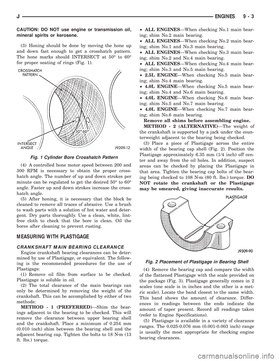
(3) Honing should be done by moving the hone up
and down fast enough to get a crosshatch pattern.
The hone marks should INTERSECT at 50É to 60É
for proper seating of rings (Fig. 1).
(4) A controlled hone motor speed between 200 and
300 RPM is necessary to obtain the proper cross-
hatch angle. The number of up and down strokes per
minute can be regulated to get the desired 50É to 60É
angle. Faster up and down strokes increase the cross-
hatch angle.
(5) After honing, it is necessary that the block be
cleaned to remove all traces of abrasive. Use a brush
to wash parts with a solution of hot water and deter-
gent. Dry parts thoroughly. Use a clean, white, lint-
free cloth to check that the bore is clean. Oil the
bores after cleaning to prevent rusting.
MEASURING WITH PLASTIGAGE
CRANKSHAFT MAIN BEARING CLEARANCE
Engine crankshaft bearing clearances can be deter-
mined by use of Plastigage, or equivalent. The follow-
ing is the recommended procedures for the use of
Plastigage:
(1) Remove oil film from surface to be checked.
Plastigage is soluble in oil.
(2) The total clearance of the main bearings can
only be determined by removing the weight of the
crankshaft. This can be accomplished by either of two
methods:
METHOD - 1 (PREFERRED)ÐShim the bear-
ings adjacent to the bearing to be checked. This will
remove the clearance between upper bearing shell
and the crankshaft. Place a minimum of 0.254 mm
(0.010 inch) shim between the bearing shell and the
adjacent bearing cap. Tighten the bolts to 18 Nzm (13
ft. lbs.) torque.²ALL ENGINESÐWhen checking No.1 main bear-
ing; shim No.2 main bearing.
²ALL ENGINESÐWhen checking No.2 main bear-
ing; shim No.1 and No.3 main bearing.
²ALL ENGINESÐWhen checking No.3 main bear-
ing; shim No.2 and No.4 main bearing.
²ALL ENGINESÐWhen checking No.4 main bear-
ing; shim No.3 and No.5 main bearing.
²2.5L ENGINEÐWhen checking No.5 main bear-
ing; shim No.4 main bearing.
²4.0L ENGINEÐWhen checking No.5 main bear-
ing; shim No.4 and No.6 main bearing.
²4.0L ENGINEÐWhen checking No.6 main bear-
ing; shim No.5 and No.7 main bearing.
²4.0L ENGINEÐWhen checking No.7 main bear-
ing; shim No.6 main bearing.
Remove all shims before assembling engine.
METHOD - 2 (ALTERNATIVE)ÐThe weight of
the crankshaft is supported by a jack under the coun-
terweight adjacent to the bearing being checked.
(3) Place a piece of Plastigage across the entire
width of the bearing cap shell (Fig. 2). Position the
Plastigage approximately 6.35 mm (1/4 inch) off cen-
ter and away from the oil holes. In addition, suspect
areas can be checked by placing the Plastigage in
that area. Tighten the bearing cap bolts of the bear-
ing being checked to 108 Nzm (80 ft. lbs.) torque.DO
NOT rotate the crankshaft or the Plastigage
may be smeared, giving inaccurate results.
(4) Remove the bearing cap and compare the width
of the flattened Plastigage with the scale provided on
the package (Fig. 3). Plastigage generally comes in 2
scales (one scale is in inches and the other is a met-
ric scale). Locate the band closest to the same width.
This band shows the amount of clearance. Differ-
ences in readings between the ends indicate the
amount of taper present. Record all readings taken
(refer to Engine Specifications).
(5) Plastigage is available in a variety of clearance
ranges. The 0.025-0.076 mm (0.001-0.003 inch) range
is usually the most appropriate for checking engine
bearing clearances.
Fig. 1 Cylinder Bore Crosshatch Pattern
Fig. 2 Placement of Plastigage in Bearing Shell
JENGINES 9 - 3
Page 1319 of 2158
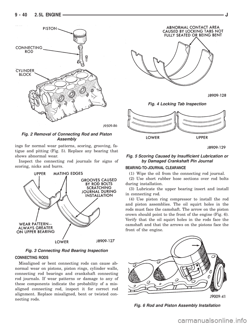
ings for normal wear patterns, scoring, grooving, fa-
tigue and pitting (Fig. 5). Replace any bearing that
shows abnormal wear.
Inspect the connecting rod journals for signs of
scoring, nicks and burrs.
CONNECTING RODS
Misaligned or bent connecting rods can cause ab-
normal wear on pistons, piston rings, cylinder walls,
connecting rod bearings and crankshaft connecting
rod journals. If wear patterns or damage to any of
these components indicate the probability of a mis-
aligned connecting rod, inspect it for correct rod
alignment. Replace misaligned, bent or twisted con-
necting rods.BEARING-TO-JOURNAL CLEARANCE
(1) Wipe the oil from the connecting rod journal.
(2) Use short rubber hose sections over rod bolts
during installation.
(3) Lubricate the upper bearing insert and install
in connecting rod.
(4) Use piston ring compressor to install the rod
and piston assemblies. The oil squirt holes in the
rods must face the camshaft. The arrow on the piston
crown should point to the front of the engine (Fig. 6).
Verify that the oil squirt holes in the rods face the
camshaft and that the arrows on the pistons face the
front of the engine.
Fig. 2 Removal of Connecting Rod and Piston
Assembly
Fig. 3 Connecting Rod Bearing Inspection
Fig. 4 Locking Tab Inspection
Fig. 5 Scoring Caused by Insufficient Lubrication or
by Damaged Crankshaft Pin Journal
Fig. 6 Rod and Piston Assembly Installation
9 - 40 2.5L ENGINEJ
Page 1325 of 2158
FITTING (CRANKSHAFT INSTALLED)
The main bearing caps, numbered (front to rear)
from 1 through 5 have an arrow to indicate the for-
ward position. The upper main bearing inserts are
grooved to provide oil channels while the lower in-
serts are smooth.
Each bearing insert pair is selectively fitted to its
respective journal to obtain the specified operating
clearance. In production, the select fit is obtained by
using various-sized color-coded bearing insert pairs
as listed in the Main Bearing Fitting Chart. The
bearing color code appears on the edge of the insert.
The size is not stamped on bearing inserts used
for engine production.
The main bearing journal size (diameter) is identi-
fied by a color-coded paint mark on the adjacent
cheek. The rear main journal, is identified by a color-
coded paint mark on the crankshaft rear flange.
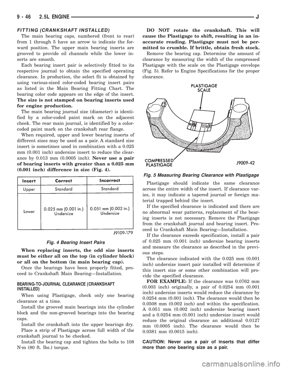
When required, upper and lower bearing inserts of
different sizes may be used as a pair. A standard size
insert is sometimes used in combination with a 0.025
mm (0.001 inch) undersize insert to reduce the clear-
ance by 0.013 mm (0.0005 inch).Never use a pair
of bearing inserts with greater than a 0.025 mm
(0.001 inch) difference in size (Fig. 4).
When replacing inserts, the odd size inserts
must be either all on the top (in cylinder block)
or all on the bottom (in main bearing cap).
Once the bearings have been properly fitted, pro-
ceed to Crankshaft Main BearingÐInstallation.
BEARING-TO-JOURNAL CLEARANCE (CRANKSHAFT
INSTALLED)
When using Plastigage, check only one bearing
clearance at a time.
Install the grooved main bearings into the cylinder
block and the non-grooved bearings into the bearing
caps.
Install the crankshaft into the upper bearings dry.
Place a strip of Plastigage across full width of the
crankshaft journal to be checked.
Install the bearing cap and tighten the bolts to 108
Nzm (80 ft. lbs.) torque.DO NOT rotate the crankshaft. This will
cause the Plastigage to shift, resulting in an in-
accurate reading. Plastigage must not be per-
mitted to crumble. If brittle, obtain fresh stock.
Remove the bearing cap. Determine the amount of
clearance by measuring the width of the compressed
Plastigage with the scale on the Plastigage envelope
(Fig. 5). Refer to Engine Specifications for the proper
clearance.
Plastigage should indicate the same clearance
across the entire width of the insert. If clearance var-
ies, it may indicate a tapered journal or foreign ma-
terial trapped behind the insert.
If the specified clearance is indicated and there are
no abnormal wear patterns, replacement of the bear-
ing inserts is not necessary. Remove the Plastigage
from the crankshaft journal and bearing insert. Pro-
ceed to Crankshaft Main BearingÐInstallation.
If the clearance exceeds specification, install a pair
of 0.025 mm (0.001 inch) undersize bearing inserts
and measure the clearance as described in the previ-
ous steps.
The clearance indicated with the 0.025 mm (0.001
inch) undersize insert pair installed will determine if
this insert size or some other combination will pro-
vide the specified clearance.
FOR EXAMPLE:If the clearance was 0.0762 mm
(0.003 inch) originally, a pair of 0.0254 mm (0.001
inch) undersize inserts would reduce the clearance by
0.0254 mm (0.001 inch). The clearance would then be
0.0508 mm (0.002 inch) and within the specification.
A 0.051 mm (0.002 inch) undersize bearing insert
and a 0.0254 mm (0.001 inch) undersize insert would
reduce the original clearance an additional 0.0127
mm (0.0005 inch). The clearance would then be
0.0381 mm (0.0015 inch).
CAUTION: Never use a pair of inserts that differ
more than one bearing size as a pair.
Fig. 4 Bearing Insert Pairs
Fig. 5 Measuring Bearing Clearance with Plastigage
9 - 46 2.5L ENGINEJ
Page 1361 of 2158
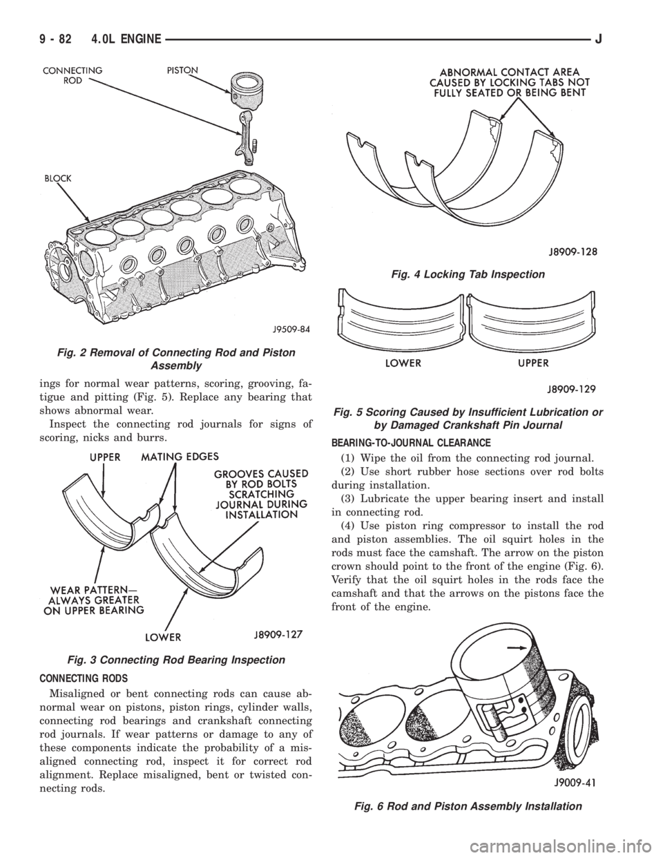
ings for normal wear patterns, scoring, grooving, fa-
tigue and pitting (Fig. 5). Replace any bearing that
shows abnormal wear.
Inspect the connecting rod journals for signs of
scoring, nicks and burrs.
CONNECTING RODS
Misaligned or bent connecting rods can cause ab-
normal wear on pistons, piston rings, cylinder walls,
connecting rod bearings and crankshaft connecting
rod journals. If wear patterns or damage to any of
these components indicate the probability of a mis-
aligned connecting rod, inspect it for correct rod
alignment. Replace misaligned, bent or twisted con-
necting rods.BEARING-TO-JOURNAL CLEARANCE
(1) Wipe the oil from the connecting rod journal.
(2) Use short rubber hose sections over rod bolts
during installation.
(3) Lubricate the upper bearing insert and install
in connecting rod.
(4) Use piston ring compressor to install the rod
and piston assemblies. The oil squirt holes in the
rods must face the camshaft. The arrow on the piston
crown should point to the front of the engine (Fig. 6).
Verify that the oil squirt holes in the rods face the
camshaft and that the arrows on the pistons face the
front of the engine.
Fig. 2 Removal of Connecting Rod and Piston
Assembly
Fig. 3 Connecting Rod Bearing Inspection
Fig. 4 Locking Tab Inspection
Fig. 5 Scoring Caused by Insufficient Lubrication or
by Damaged Crankshaft Pin Journal
Fig. 6 Rod and Piston Assembly Installation
9 - 82 4.0L ENGINEJ
Page 1367 of 2158
ward position. The upper main bearing inserts are
grooved to provide oil channels while the lower in-
serts are smooth.
Each bearing insert pair is selectively fitted to its
respective journal to obtain the specified operating
clearance. In production, the select fit is obtained by
using various-sized color-coded bearing insert pairs
as listed in the Main Bearing Fitting Chart. The
bearing color code appears on the edge of the insert.
The size is not stamped on bearing inserts used
for engine production.
The main bearing journal size (diameter) is identi-
fied by a color-coded paint mark on the adjacent
cheek. The rear main journal, is identified by a color-
coded paint mark on the crankshaft rear flange.
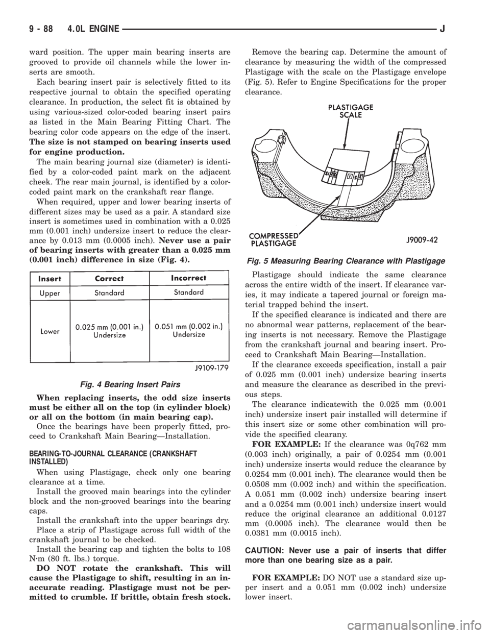
When required, upper and lower bearing inserts of
different sizes may be used as a pair. A standard size
insert is sometimes used in combination with a 0.025
mm (0.001 inch) undersize insert to reduce the clear-
ance by 0.013 mm (0.0005 inch).Never use a pair
of bearing inserts with greater than a 0.025 mm
(0.001 inch) difference in size (Fig. 4).
When replacing inserts, the odd size inserts
must be either all on the top (in cylinder block)
or all on the bottom (in main bearing cap).
Once the bearings have been properly fitted, pro-
ceed to Crankshaft Main BearingÐInstallation.
BEARING-TO-JOURNAL CLEARANCE (CRANKSHAFT
INSTALLED)
When using Plastigage, check only one bearing
clearance at a time.
Install the grooved main bearings into the cylinder
block and the non-grooved bearings into the bearing
caps.
Install the crankshaft into the upper bearings dry.
Place a strip of Plastigage across full width of the
crankshaft journal to be checked.
Install the bearing cap and tighten the bolts to 108
Nzm (80 ft. lbs.) torque.
DO NOT rotate the crankshaft. This will
cause the Plastigage to shift, resulting in an in-
accurate reading. Plastigage must not be per-
mitted to crumble. If brittle, obtain fresh stock.Remove the bearing cap. Determine the amount of
clearance by measuring the width of the compressed
Plastigage with the scale on the Plastigage envelope
(Fig. 5). Refer to Engine Specifications for the proper
clearance.
Plastigage should indicate the same clearance
across the entire width of the insert. If clearance var-
ies, it may indicate a tapered journal or foreign ma-
terial trapped behind the insert.
If the specified clearance is indicated and there are
no abnormal wear patterns, replacement of the bear-
ing inserts is not necessary. Remove the Plastigage
from the crankshaft journal and bearing insert. Pro-
ceed to Crankshaft Main BearingÐInstallation.
If the clearance exceeds specification, install a pair
of 0.025 mm (0.001 inch) undersize bearing inserts
and measure the clearance as described in the previ-
ous steps.
The clearance indicatewith the 0.025 mm (0.001
inch) undersize insert pair installed will determine if
this insert size or some other combination will pro-
vide the specified clearany.
FOR EXAMPLE:If the clearance was 0q762 mm
(0.003 inch) originally, a pair of 0.0254 mm (0.001
inch) undersize inserts would reduce the clearance by
0.0254 mm (0.001 inch). The clearance would then be
0.0508 mm (0.002 inch) and within the specification.
A 0.051 mm (0.002 inch) undersize bearing insert
and a 0.0254 mm (0.001 inch) undersize insert would
reduce the original clearance an additional 0.0127
mm (0.0005 inch). The clearance would then be
0.0381 mm (0.0015 inch).
CAUTION: Never use a pair of inserts that differ
more than one bearing size as a pair.
FOR EXAMPLE:DO NOT use a standard size up-
per insert and a 0.051 mm (0.002 inch) undersize
lower insert.
Fig. 4 Bearing Insert Pairs
Fig. 5 Measuring Bearing Clearance with Plastigage
9 - 88 4.0L ENGINEJ
Page 1564 of 2158
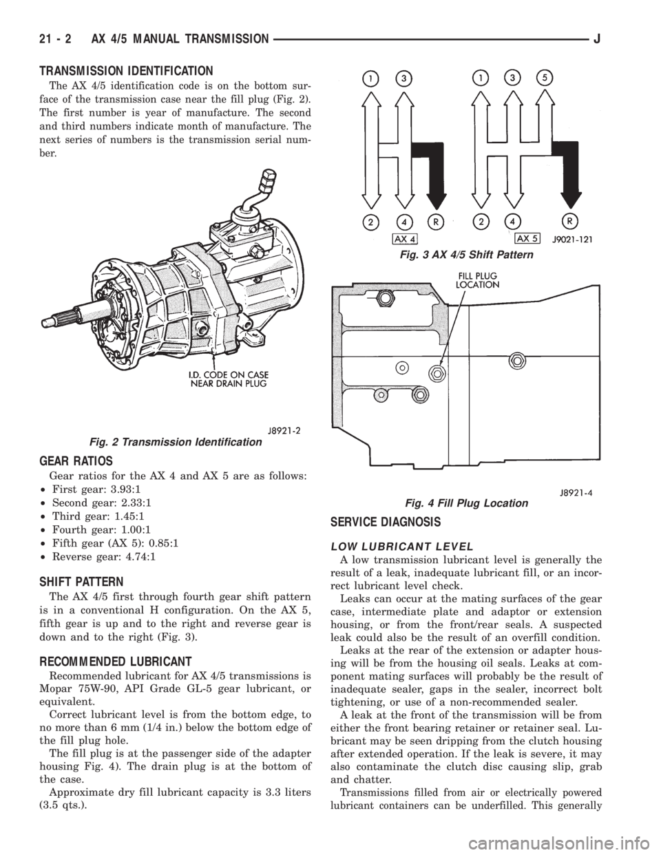
TRANSMISSION IDENTIFICATION
The AX 4/5 identification code is on the bottom sur-
face of the transmission case near the fill plug (Fig. 2).
The first number is year of manufacture. The second
and third numbers indicate month of manufacture. The
next series of numbers is the transmission serial num-
ber.
GEAR RATIOS
Gear ratios for the AX 4 and AX 5 are as follows:
²First gear: 3.93:1
²Second gear: 2.33:1
²Third gear: 1.45:1
²Fourth gear: 1.00:1
²Fifth gear (AX 5): 0.85:1
²Reverse gear: 4.74:1
SHIFT PATTERN
The AX 4/5 first through fourth gear shift pattern
is in a conventional H configuration. On the AX 5,
fifth gear is up and to the right and reverse gear is
down and to the right (Fig. 3).
RECOMMENDED LUBRICANT
Recommended lubricant for AX 4/5 transmissions is
Mopar 75W-90, API Grade GL-5 gear lubricant, or
equivalent.
Correct lubricant level is from the bottom edge, to
no more than 6 mm (1/4 in.) below the bottom edge of
the fill plug hole.
The fill plug is at the passenger side of the adapter
housing Fig. 4). The drain plug is at the bottom of
the case.
Approximate dry fill lubricant capacity is 3.3 liters
(3.5 qts.).
SERVICE DIAGNOSIS
LOW LUBRICANT LEVEL
A low transmission lubricant level is generally the
result of a leak, inadequate lubricant fill, or an incor-
rect lubricant level check.
Leaks can occur at the mating surfaces of the gear
case, intermediate plate and adaptor or extension
housing, or from the front/rear seals. A suspected
leak could also be the result of an overfill condition.
Leaks at the rear of the extension or adapter hous-
ing will be from the housing oil seals. Leaks at com-
ponent mating surfaces will probably be the result of
inadequate sealer, gaps in the sealer, incorrect bolt
tightening, or use of a non-recommended sealer.
A leak at the front of the transmission will be from
either the front bearing retainer or retainer seal. Lu-
bricant may be seen dripping from the clutch housing
after extended operation. If the leak is severe, it may
also contaminate the clutch disc causing slip, grab
and chatter.
Transmissions filled from air or electrically powered
lubricant containers can be underfilled. This generally
Fig. 2 Transmission Identification
Fig. 3 AX 4/5 Shift Pattern
Fig. 4 Fill Plug Location
21 - 2 AX 4/5 MANUAL TRANSMISSIONJ
Page 1596 of 2158
The first number is year of manufacture. The sec-
ond and third numbers indicate month of manufac-
ture. The next series of numbers is the transmission
serial number.
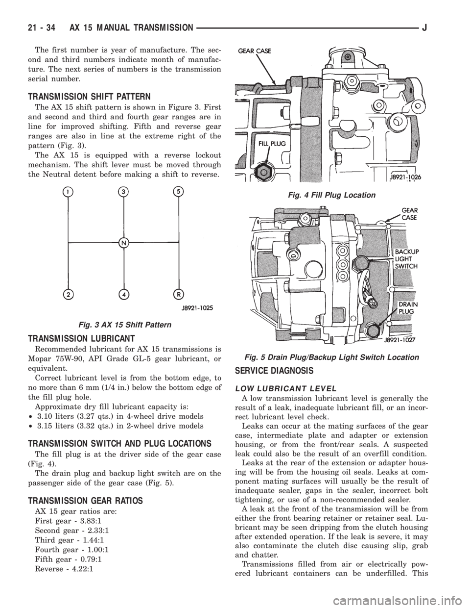
TRANSMISSION SHIFT PATTERN
The AX 15 shift pattern is shown in Figure 3. First
and second and third and fourth gear ranges are in
line for improved shifting. Fifth and reverse gear
ranges are also in line at the extreme right of the
pattern (Fig. 3).
The AX 15 is equipped with a reverse lockout
mechanism. The shift lever must be moved through
the Neutral detent before making a shift to reverse.
TRANSMISSION LUBRICANT
Recommended lubricant for AX 15 transmissions is
Mopar 75W-90, API Grade GL-5 gear lubricant, or
equivalent.
Correct lubricant level is from the bottom edge, to
no more than 6 mm (1/4 in.) below the bottom edge of
the fill plug hole.
Approximate dry fill lubricant capacity is:
²3.10 liters (3.27 qts.) in 4-wheel drive models
²3.15 liters (3.32 qts.) in 2-wheel drive models
TRANSMISSION SWITCH AND PLUG LOCATIONS
The fill plug is at the driver side of the gear case
(Fig. 4).
The drain plug and backup light switch are on the
passenger side of the gear case (Fig. 5).
TRANSMISSION GEAR RATIOS
AX 15 gear ratios are:
First gear - 3.83:1
Second gear - 2.33:1
Third gear - 1.44:1
Fourth gear - 1.00:1
Fifth gear - 0.79:1
Reverse - 4.22:1
SERVICE DIAGNOSIS
LOW LUBRICANT LEVEL
A low transmission lubricant level is generally the
result of a leak, inadequate lubricant fill, or an incor-
rect lubricant level check.
Leaks can occur at the mating surfaces of the gear
case, intermediate plate and adapter or extension
housing, or from the front/rear seals. A suspected
leak could also be the result of an overfill condition.
Leaks at the rear of the extension or adapter hous-
ing will be from the housing oil seals. Leaks at com-
ponent mating surfaces will usually be the result of
inadequate sealer, gaps in the sealer, incorrect bolt
tightening, or use of a non-recommended sealer.
A leak at the front of the transmission will be from
either the front bearing retainer or retainer seal. Lu-
bricant may be seen dripping from the clutch housing
after extended operation. If the leak is severe, it may
also contaminate the clutch disc causing slip, grab
and chatter.
Transmissions filled from air or electrically pow-
ered lubricant containers can be underfilled. This
Fig. 3 AX 15 Shift Pattern
Fig. 4 Fill Plug Location
Fig. 5 Drain Plug/Backup Light Switch Location
21 - 34 AX 15 MANUAL TRANSMISSIONJ