1995 JEEP YJ instrument panel
[x] Cancel search: instrument panelPage 2070 of 2158
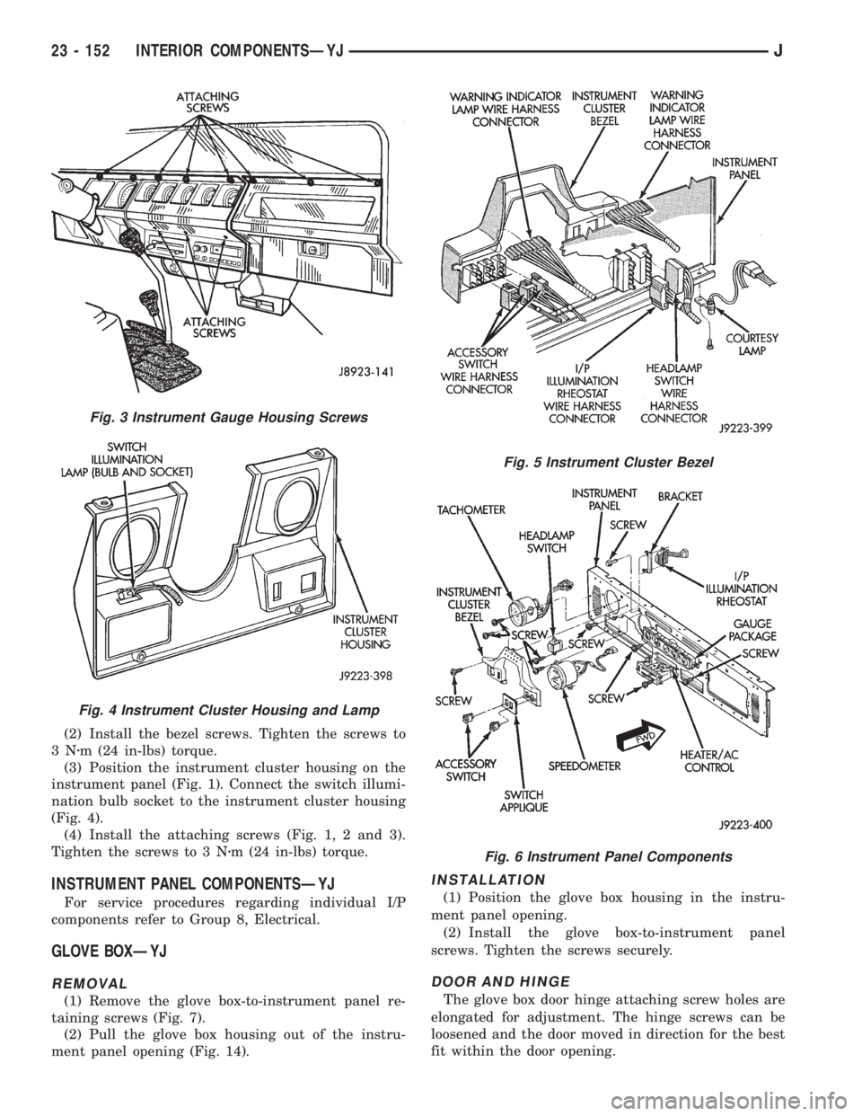
(2) Install the bezel screws. Tighten the screws to
3Nzm (24 in-lbs) torque.
(3) Position the instrument cluster housing on the
instrument panel (Fig. 1). Connect the switch illumi-
nation bulb socket to the instrument cluster housing
(Fig. 4).
(4) Install the attaching screws (Fig. 1, 2 and 3).
Tighten the screws to 3 Nzm (24 in-lbs) torque.
INSTRUMENT PANEL COMPONENTSÐYJ
For service procedures regarding individual I/P
components refer to Group 8, Electrical.
GLOVE BOXÐYJ
REMOVAL
(1) Remove the glove box-to-instrument panel re-
taining screws (Fig. 7).
(2) Pull the glove box housing out of the instru-
ment panel opening (Fig. 14).
INSTALLATION
(1) Position the glove box housing in the instru-
ment panel opening.
(2) Install the glove box-to-instrument panel
screws. Tighten the screws securely.
DOOR AND HINGE
The glove box door hinge attaching screw holes are
elongated for adjustment. The hinge screws can be
loosened and the door moved in direction for the best
fit within the door opening.
Fig. 3 Instrument Gauge Housing Screws
Fig. 4 Instrument Cluster Housing and Lamp
Fig. 5 Instrument Cluster Bezel
Fig. 6 Instrument Panel Components
23 - 152 INTERIOR COMPONENTSÐYJJ
Page 2097 of 2158
(6) Test A/C blower switch HIGH terminal with
blower switch in HIGH, should be battery voltage. If
not, replace switch.
BLOWER MOTOR
The A/C blower motor is attached to the evaporator
housing mounted under the instrument panel. The
motor has a ground wire and 3 wires connect to the
motor brushes. When voltage is applied to the sepa-
rate brushes it provides the 3 blower speeds LO,
MED, and HIGH.
BLOWER MOTOR TEST
Turn ignition switch to RUN for voltage tests and
turn ignition switch to OFF for resistance test.
(1) Test A/C blower motor ground terminal should
be 0 ohms. If not, repair ground circuit.
(2) Test A/C blower motor connector LO terminal
with blower switch in LO, should be battery voltage.
If not repair open from blower switch. If the blower
motor is still inoperative replace motor.
(3) Test A/C blower motor connector MED terminal
with blower switch in MED, should be battery volt-
age. If not repair open from blower switch. If the
blower motor is still inoperative replace motor.
(4) Test A/C blower motor connector HIGH termi-
nal with blower switch in HIGH, should be battery
voltage. If not, repair open from blower switch. If the
blower motor is still inoperative, replace motor.
HEATER DIAGNOSIS
On LHD XJ vehicles a water valve controls coolant
flow to the heater core. The valve is vacuum oper-
ated. When vacuum is applied, the valve opens and
coolant is directed through the heater core and back
to the engine. When the water valve is closed (no
vacuum applied) coolant flow bypasses the heater
core back to the engine.
The heating system receives its battery feed from
the fuse box. On YJ vehicles the feed circuit runs to
the HEATER/OFF switch and then to the BLOWER
switch. On XJ vehicles the feed circuit runs to the
HEAT/MODE switch and then to the BLOWER
switch.
The blower speed is controlled by the blower switch
and blower resistors. With the switch in LO, battery
voltage is supplied to the motor through all of the re-
sistors. The motor runs slowly. When the blower
switch is moved to a higher speed, battery voltage in-
creases to the blower motor which increase its speed.
This is accomplished by bypassing some of the blower
resistors. When the switch is in HI, blower resistors
are bypassed and battery voltage is applied directly
to the blower motor.
The following chart has been developed for quick
reference.
Refer to the Group 8W Wiring Diagrams for com-
plete wiring schematic.
JHEATING AND AIR CONDITIONING 24 - 17
Page 2103 of 2158
COMPONENT SERVICEÐXJ VEHICLES
INDEX
page page
A/C Recirculating Door Vacuum Motor
Replacement........................... 27
Blower Motor Resistors Replacement.......... 31
Blower Motor/Fan Replacement............... 24
Condenser Filter DrierÐ2.5L Engines.......... 27
CondenserÐ4.0L Engines................... 28
Description.............................. 23
Evaporator Coil........................... 30
Evaporator/Blower Housing.................. 29Expansion Valve.......................... 31
Filter DrierÐ4.0L Engines................... 28
Fin Sensing Cycling Clutch Switch............. 31
Heater and A/C Control Replacement.......... 23
Heater Core............................. 26
Heater Housing Replacement................ 26
Heater/Defroster/Instrument Panel Outlet Vacuum
Motor Replacement...................... 26
DESCRIPTION
The Climate Control System combines air condi-
tioning, heating and ventilating capabilities for vehi-
cles equipped with air conditioning. Vehicles without
air conditioning perform heating and ventilating
functions without the air conditioning evaporator.
Both systems consist basically of 2 parts:
²Blower and Air Inlet Assembly
²Heater Core and Air Distribution Assembly
These unit may be removed separately from under
the instrument panel for service.
HEATER AND A/C CONTROL REPLACEMENT
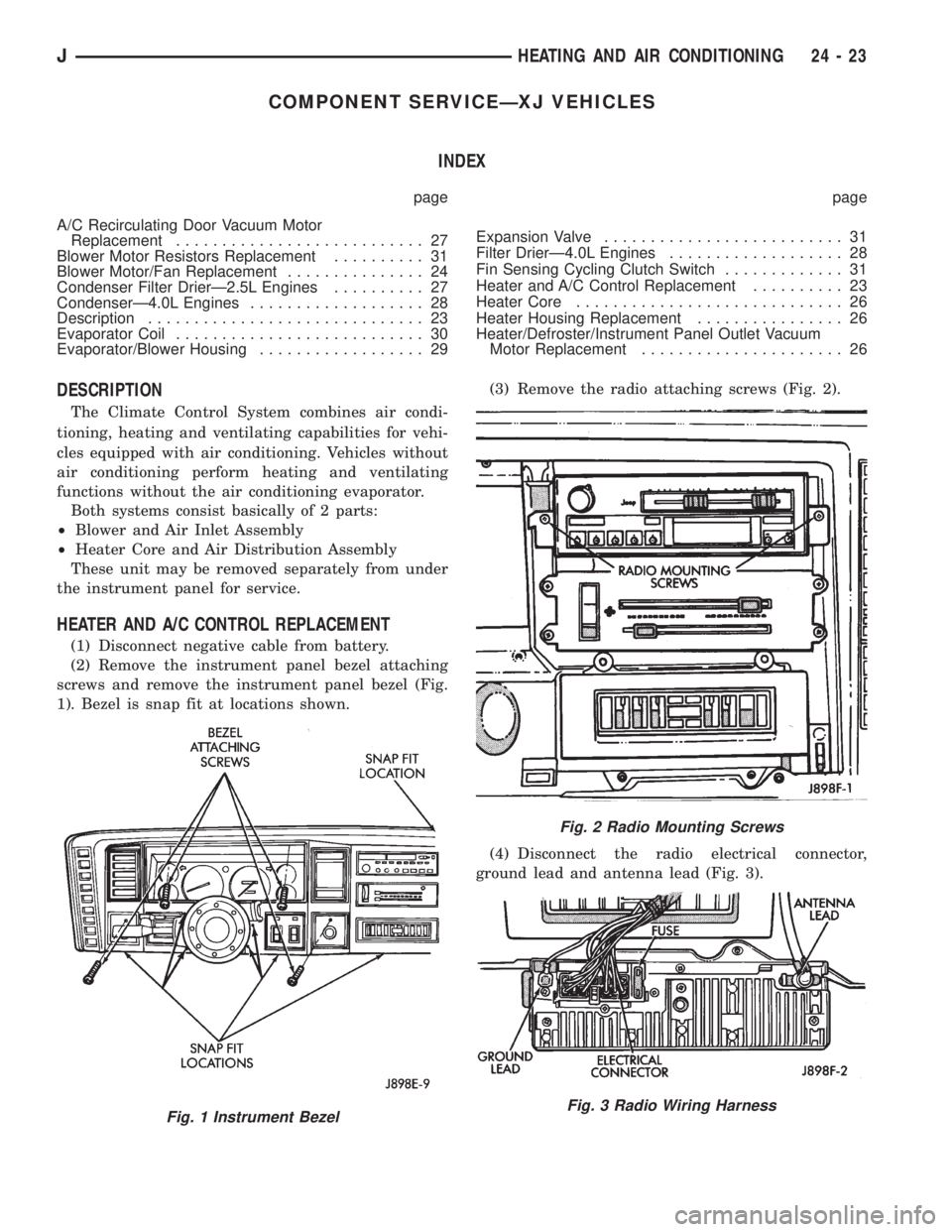
(1) Disconnect negative cable from battery.
(2) Remove the instrument panel bezel attaching
screws and remove the instrument panel bezel (Fig.
1). Bezel is snap fit at locations shown.(3) Remove the radio attaching screws (Fig. 2).
(4) Disconnect the radio electrical connector,
ground lead and antenna lead (Fig. 3).
Fig. 1 Instrument Bezel
Fig. 2 Radio Mounting Screws
Fig. 3 Radio Wiring Harness
JHEATING AND AIR CONDITIONING 24 - 23
Page 2106 of 2158
HEATER CORE
REVIEW WARNINGS AND CAUTIONS IN
THIS GROUP BEFORE PERFORMING THIS
OPERATION.
REMOVAL
(1) Drain the radiator.
(2) Disconnect heater hoses at heater core tubes.
(3) Remove heater/evaporator housing side cover.
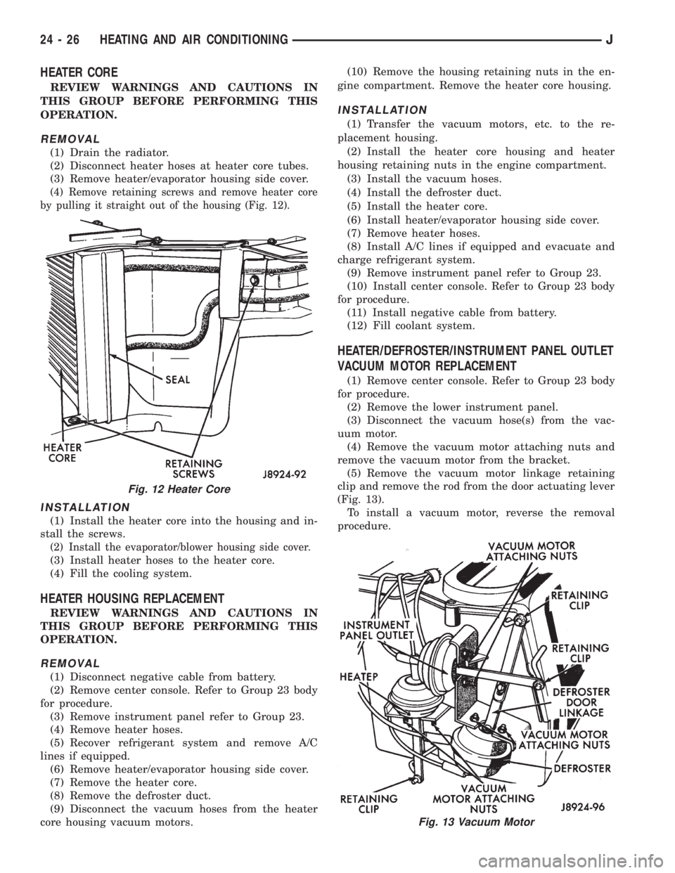
(4) Remove retaining screws and remove heater core
by pulling it straight out of the housing (Fig. 12).
INSTALLATION
(1) Install the heater core into the housing and in-
stall the screws.
(2) Install the evaporator/blower housing side cover.
(3) Install heater hoses to the heater core.
(4) Fill the cooling system.
HEATER HOUSING REPLACEMENT
REVIEW WARNINGS AND CAUTIONS IN
THIS GROUP BEFORE PERFORMING THIS
OPERATION.
REMOVAL
(1) Disconnect negative cable from battery.
(2) Remove center console. Refer to Group 23 body
for procedure.
(3) Remove instrument panel refer to Group 23.
(4) Remove heater hoses.
(5) Recover refrigerant system and remove A/C
lines if equipped.
(6) Remove heater/evaporator housing side cover.
(7) Remove the heater core.
(8) Remove the defroster duct.
(9) Disconnect the vacuum hoses from the heater
core housing vacuum motors.(10) Remove the housing retaining nuts in the en-
gine compartment. Remove the heater core housing.
INSTALLATION
(1) Transfer the vacuum motors, etc. to the re-
placement housing.
(2) Install the heater core housing and heater
housing retaining nuts in the engine compartment.
(3) Install the vacuum hoses.
(4) Install the defroster duct.
(5) Install the heater core.
(6) Install heater/evaporator housing side cover.
(7) Remove heater hoses.
(8) Install A/C lines if equipped and evacuate and
charge refrigerant system.
(9) Remove instrument panel refer to Group 23.
(10) Install center console. Refer to Group 23 body
for procedure.
(11) Install negative cable from battery.
(12) Fill coolant system.
HEATER/DEFROSTER/INSTRUMENT PANEL OUTLET
VACUUM MOTOR REPLACEMENT
(1) Remove center console. Refer to Group 23 body
for procedure.
(2) Remove the lower instrument panel.
(3) Disconnect the vacuum hose(s) from the vac-
uum motor.
(4) Remove the vacuum motor attaching nuts and
remove the vacuum motor from the bracket.
(5) Remove the vacuum motor linkage retaining
clip and remove the rod from the door actuating lever
(Fig. 13).
To install a vacuum motor, reverse the removal
procedure.
Fig. 12 Heater Core
Fig. 13 Vacuum Motor
24 - 26 HEATING AND AIR CONDITIONINGJ
Page 2109 of 2158
(1) Install the filter drier.
(2) Install and tighten the nut attaching the filter
drier to the side sill weld stud.
(3) Plug the harness to the low pressure switch.
(4) Remove the plugs the openings. Connect the
A/C hoses to the receiver dryer.
(5) Evacuate and charge the A/C system.
EVAPORATOR/BLOWER HOUSING
REVIEW WARNINGS AND CAUTIONS IN
THIS GROUP BEFORE PERFORMING THIS
OPERATION.
REMOVAL
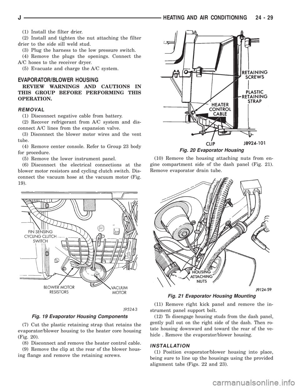
(1) Disconnect negative cable from battery.
(2) Recover refrigerant from A/C system and dis-
connect A/C lines from the expansion valve.
(3) Disconnect the blower motor wires and the vent
tube.
(4) Remove center console. Refer to Group 23 body
for procedure.
(5) Remove the lower instrument panel.
(6) Disconnect the electrical connections at the
blower motor resistors and cycling clutch switch. Dis-
connect the vacuum hose at the vacuum motor (Fig.
19).
(7) Cut the plastic retaining strap that retains the
evaporator/blower housing to the heater core housing
(Fig. 20).
(8) Disconnect and remove the heater control cable.
(9) Remove the clip at the rear of the blower hous-
ing flange and remove the retaining screws.(10) Remove the housing attaching nuts from en-
gine compartment side of the dash panel (Fig. 21).
Remove evaporator drain tube.
(11) Remove right kick panel and remove the in-
strument panel support bolt.
(12) To disengage housing studs from the dash panel,
gently pull out on the right side of the dash. Then ro-
tate housing downward and toward the rear of the ve-
hicle . Remove the evaporator/blower housing.
INSTALLATION
(1) Position evaporator/blower housing into place,
being sure to line up the housings using the provided
alignment tabs (Figs. 22 and 23).
Fig. 19 Evaporator Housing Components
Fig. 20 Evaporator Housing
Fig. 21 Evaporator Housing Mounting
JHEATING AND AIR CONDITIONING 24 - 29
Page 2110 of 2158
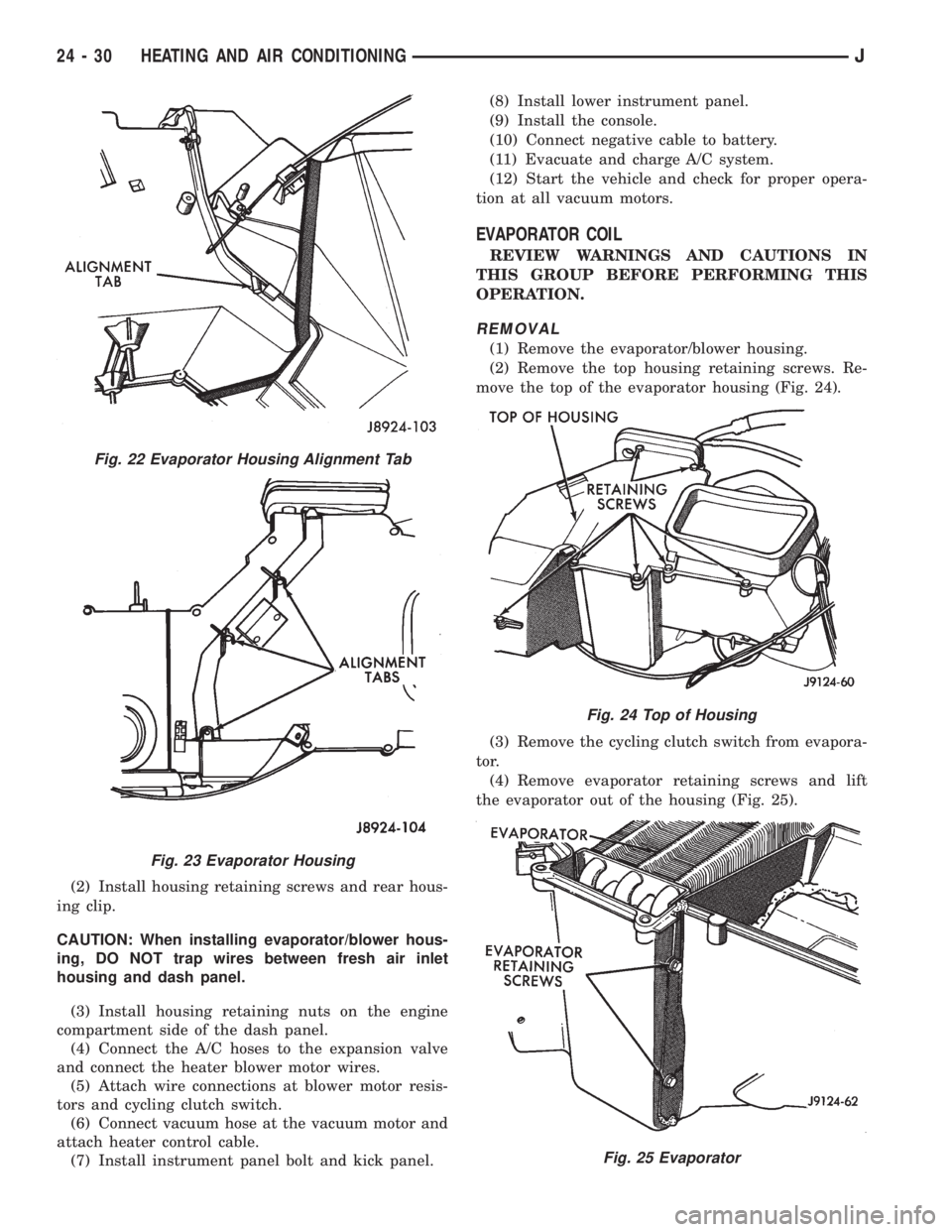
(2) Install housing retaining screws and rear hous-
ing clip.
CAUTION: When installing evaporator/blower hous-
ing, DO NOT trap wires between fresh air inlet
housing and dash panel.
(3) Install housing retaining nuts on the engine
compartment side of the dash panel.
(4) Connect the A/C hoses to the expansion valve
and connect the heater blower motor wires.
(5) Attach wire connections at blower motor resis-
tors and cycling clutch switch.
(6) Connect vacuum hose at the vacuum motor and
attach heater control cable.
(7) Install instrument panel bolt and kick panel.(8) Install lower instrument panel.
(9) Install the console.
(10) Connect negative cable to battery.
(11) Evacuate and charge A/C system.
(12) Start the vehicle and check for proper opera-
tion at all vacuum motors.
EVAPORATOR COIL
REVIEW WARNINGS AND CAUTIONS IN
THIS GROUP BEFORE PERFORMING THIS
OPERATION.
REMOVAL
(1) Remove the evaporator/blower housing.
(2) Remove the top housing retaining screws. Re-
move the top of the evaporator housing (Fig. 24).
(3) Remove the cycling clutch switch from evapora-
tor.
(4) Remove evaporator retaining screws and lift
the evaporator out of the housing (Fig. 25).
Fig. 22 Evaporator Housing Alignment Tab
Fig. 23 Evaporator Housing
Fig. 24 Top of Housing
Fig. 25 Evaporator
24 - 30 HEATING AND AIR CONDITIONINGJ
Page 2111 of 2158
(5) Remove expansion valve from the evaporator.
INSTALLATION
Add 30 ml (1 fluid oz.) of refrigerant oil to the A/C
system if the evaporator is replaced.
(1) Install expansion valve on evaporator.
(2) Position evaporator in the housing. Install and
tighten the evaporator retaining screws.
(3) Install cycling clutch switch into evaporator. In-
stall the top of the evaporator housing.
(4) Install the evaporator/blower housing.
(5) Evacuate and charge A/C system as outlined in
this section.
EXPANSION VALVE
REVIEW ALL WARNINGS AND CAUTIONS IN
THIS GROUP BEFORE PERFORMING THIS
OPERATION.
REMOVAL
(1) Recover refrigerant from A/C system.
(2) Remove the coolant bottle and bracket.
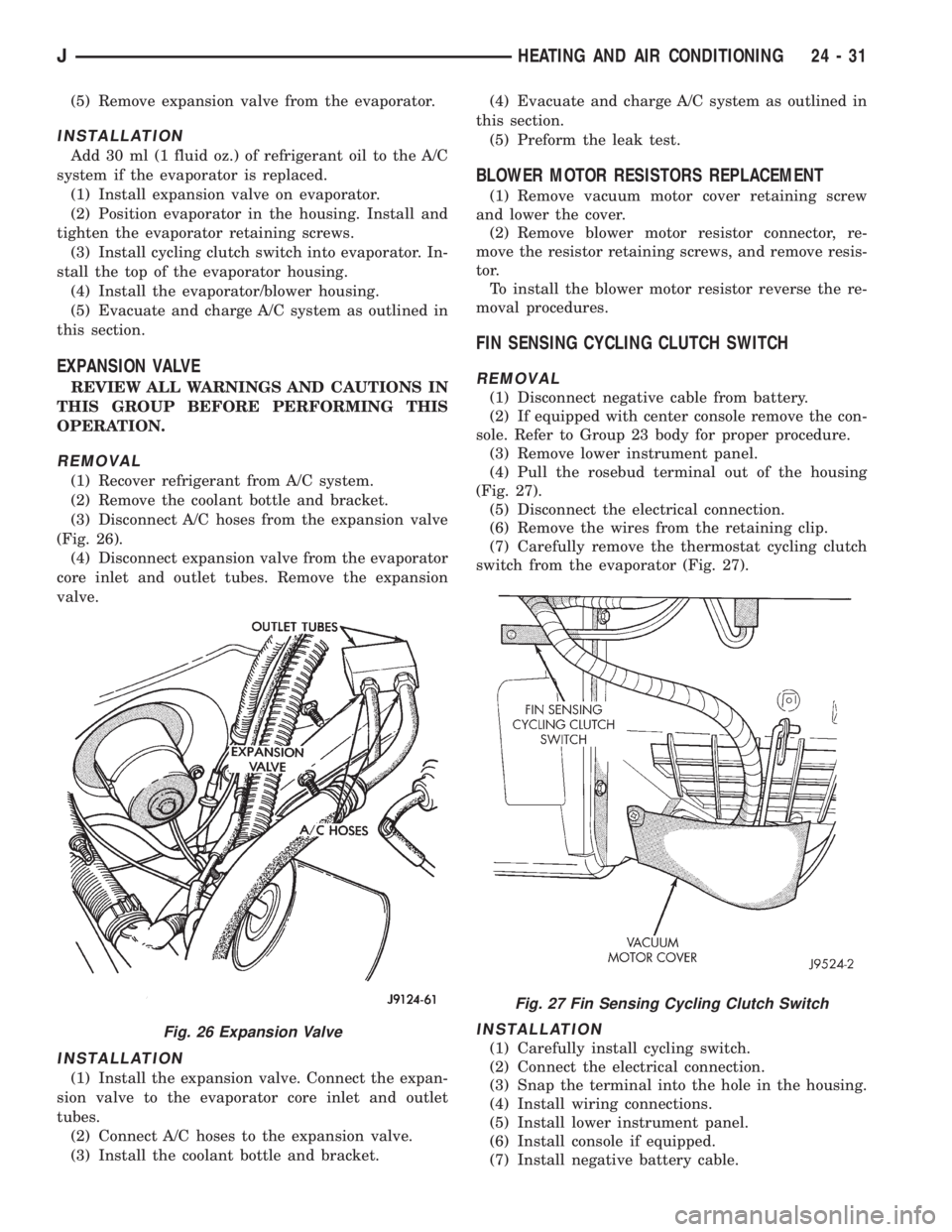
(3) Disconnect A/C hoses from the expansion valve
(Fig. 26).
(4) Disconnect expansion valve from the evaporator
core inlet and outlet tubes. Remove the expansion
valve.
INSTALLATION
(1) Install the expansion valve. Connect the expan-
sion valve to the evaporator core inlet and outlet
tubes.
(2) Connect A/C hoses to the expansion valve.
(3) Install the coolant bottle and bracket.(4) Evacuate and charge A/C system as outlined in
this section.
(5) Preform the leak test.
BLOWER MOTOR RESISTORS REPLACEMENT
(1) Remove vacuum motor cover retaining screw
and lower the cover.
(2) Remove blower motor resistor connector, re-
move the resistor retaining screws, and remove resis-
tor.
To install the blower motor resistor reverse the re-
moval procedures.
FIN SENSING CYCLING CLUTCH SWITCH
REMOVAL
(1) Disconnect negative cable from battery.
(2) If equipped with center console remove the con-
sole. Refer to Group 23 body for proper procedure.
(3) Remove lower instrument panel.
(4) Pull the rosebud terminal out of the housing
(Fig. 27).
(5) Disconnect the electrical connection.
(6) Remove the wires from the retaining clip.
(7) Carefully remove the thermostat cycling clutch
switch from the evaporator (Fig. 27).
INSTALLATION
(1) Carefully install cycling switch.
(2) Connect the electrical connection.
(3) Snap the terminal into the hole in the housing.
(4) Install wiring connections.
(5) Install lower instrument panel.
(6) Install console if equipped.
(7) Install negative battery cable.
Fig. 26 Expansion Valve
Fig. 27 Fin Sensing Cycling Clutch Switch
JHEATING AND AIR CONDITIONING 24 - 31
Page 2112 of 2158
COMPONENT SERVICEÐYJ VEHICLES
INDEX
page page
A/C Blower Motor......................... 35
A/C Condenser........................... 34
Blower Motor (Heating)..................... 33
Blower Motor/Air Door Motor Switch Replacement . 32
Defroster Nozzle and Duct.................. 33
Description.............................. 32
Evaporator and Housing.................... 35
Expansion Valve.......................... 35Fresh Air Door Vacuum Motor................ 34
Fresh Air Intake Duct...................... 34
Heater Control Replacement................. 32
Heater Core and Housing................... 33
Receiver-Drier Replacement................. 35
Temperature Control Thermostat.............. 34
Vent Door Control Cables................... 32
DESCRIPTION
The air conditioning evaporator housing is
mounted to the bottom of instrument panel. The
evaporator, blower motor, thermostat, and expansion
valve are located in the evaporator housing. The com-
pressor, condenser, receiver-dryer and refrigerant
lines are located in the engine compartment.
The heater housing is mounted to the dash panel
behind the instrument panel.
HEATER CONTROL REPLACEMENT
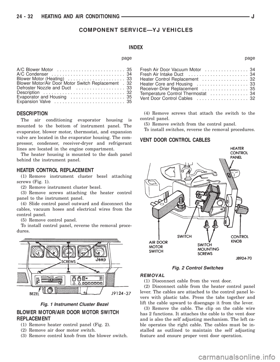
(1) Remove instrument cluster bezel attaching
screws (Fig. 1).
(2) Remove instrument cluster bezel.
(3) Remove screws attaching the heater control
panel to the instrument panel.
(4) Slide control panel outward and disconnect the
cables, vacuum hoses and electrical wires from the
control panel.
(5) Remove control panel.
To install control panel, reverse the removal proce-
dures.
BLOWER MOTOR/AIR DOOR MOTOR SWITCH
REPLACEMENT
(1) Remove heater control panel (Fig. 2).
(2) Remove air door motor switch.
(3) Remove control knob from the blower switch.(4) Remove screws that attach the switch to the
control panel.
(5) Remove switch from the control panel.
To install switches, reverse the removal procedures.
VENT DOOR CONTROL CABLES
REMOVAL
(1) Disconnect cable from the vent door.
(2) Disconnect cable from the heater control panel
lever. The cables are attached to the control panel le-
vers with plastic tabs. Press the tabs together and
lift the cable upward to disengage it from the lever.
(3) Remove the cable. The clip on the cable wire
has 2 functions. It attaches the cable to the vent door
and is also the self adjusting mechanism. The left ca-
ble operates the right cable. The cables must be in-
stalled as outlined to maintain the self adjusting
feature and ensure proper vent door operation.
Fig. 1 Instrument Cluster Bezel
Fig. 2 Control Switches
24 - 32 HEATING AND AIR CONDITIONINGJ