1995 JEEP YJ fuse
[x] Cancel search: fusePage 1210 of 2158
WIPERS
INDEX
page page
Diagram Index............................ 2
Rear Wiper System......................... 1WipersÐIntermittent........................ 1
WipersÐStandard.......................... 1
WIPERSÐSTANDARD
A circuit breaker in the fuse block powers the stan-
dard wiper system. The standard wiper system oper-
ates at either LOW or HIGH speeds.
In the ACCESSORY or RUN position, the ignition
switch connects circuit A1 from fuse 4 in the Power
Distribution Center (PDC) with circuit A31. Circuit
A31 supplies voltage to circuit V6 through the circuit
breaker in cavity 11 of the fuse block.
Circuit V6 is double crimped at the circuit breaker
and supplies power to the wiper switch and the park
switch in the wiper motor. Circuit Z1 provides
ground for the wiper motor and switch.
When the operator moves the wiper switch to the
LOW position, battery voltage passes through the
switch to circuit V3. Circuit V3 feeds the wiper motor
low speed brushes. If the operator selects wiper
HIGH speed operation, the wiper switch passes cur-
rent to circuit V4. Circuit V4 feeds the wiper motor
high speed brushes.
As the windshield wiper motor turns, the park
switch, internal to the motor, moves from its DOWN
position to the UP position. When the wiper switch is
turned OFF, the V5 circuit prevents the wipers from
stopping in any position but park.
The windshield washer uses a pump motor located
inside the windshield washer fluid reservoir. When
the washer switch is pressed, power is supplied
through the wiper switch to the pump motor on cir-
cuit V10. Circuit Z1 provide ground for the pump mo-
tor.
WIPERSÐINTERMITTENT
A circuit breaker in the fuse block powers the in-
termittent wiper system. The wiper system operates
at either LOW, HIGH, or DELAY speeds.
In the ACCESSORY or RUN position, the ignition
switch connects circuit A1 from fuse 4 in the Power
Distribution Center (PDC) with circuit A31. Circuit
A31 supplies voltage to circuit V6 through the circuit
breaker in cavity 11 of the fuse block.
Circuit V6 is double crimped at the circuit breaker
and supplies power to the wiper switch and the park
switch in the wiper motor. Circuit Z1 provides
ground for the wiper motor and switch.When the operator moves the wiper switch to the
LOW position, battery voltage passes through the
switch to circuit V3. Circuit V3 feeds the wiper motor
low speed brushes. If the operator selects wiper
HIGH speed operation, the wiper switch passes cur-
rent to circuit V4. Circuit V4 feeds the wiper motor
high speed brushes.
The DELAY portion of the wiper switch contains a
variable resistor. The variable resistor connects to
the intermittent wiper module through the wiper
switch harness. The amount of delay selected by the
operator determines the voltage drop through the re-
sistor and the voltage level received by the intermit-
tent wiper module.
After the intermittent wiper control module deter-
mines the amount of delay selected, it cycles the wip-
ers by periodically energizing circuit V3. Circuit V3
powers the wiper motor low speed brushes.
As the windshield wiper motor turns, the park
switch, internal to the motor, moves from its DOWN
position to the UP position. When the wiper switch is
turned OFF, the V5 circuit prevents the wipers from
stopping in any position but park.
The windshield washer uses a pump motor located
inside the windshield washer fluid reservoir. When
the washer switch is pressed, power is supplied
through the wiper switch to the pump motor on cir-
cuit V10. Circuit Z1 provides ground for the pump
motor.
REAR WIPER SYSTEM
In the RUN position, the ignition switch connects
circuit A1 from fuse 4 in the Power Distribution Cen-
ter (PDC) with circuit A22. Circuit A22 connects to a
fuse block in the bus bar that powers circuit V23
through the fuse in cavity 1.
Circuit V23 supplies power to the park switch in
the rear wiper motor. Also, circuit V22 is crimped to
circuit V23 at the rear wiper motor connector. Circuit
V22 supplies current to the rear wiper switch.
In the WIPE or WASH positions, the rear wiper
switch supplies voltage to the wiper motor on circuit
V13. Circuit Z1 provides ground for the wiper motor.
J8W-53 WIPERSÐYJ VEHICLES 8W - 53 - 1
Page 1211 of 2158
The rear windshield washer uses a pump motor lo-
cated inside the windshield washer fluid reservoir.
When the rear wiper switch is pressed, power is sup-
plied through the wiper switch to the pump motor on
circuit V20. Circuit Z1 provides ground for the pump
motor.DIAGRAM INDEX
Component Page
Circuit Breaker (Fuse Block Cavity 11).........8W-53-4, 5
Fuse 4 (PDC).......................8W-53-3, 4, 5,
Fuse 4 (Fuse Block).....................8W-53-4, 5
Fuse 7 (Fuse Block).....................8W-53-4, 5
Ignition Switch......................8W-53-3, 4, 5
Intermittent Wiper Control Module.............8W-53-5
Intermittent Wiper Switch...................8W-53-5
Rear Windshield Washer Pump Motor...........8W-53-3
Rear Wiper Motor........................8W-53-3
Standard Wiper Switch.....................8W-53-4
Windshield Washer Pump Motor.............8W-53-4, 5
Wiper Motor..........................8W-53-4, 5
8W - 53 - 2 8W-53 WIPERSÐYJ VEHICLESJ
Page 1262 of 2158
CONNECTOR LOCATIONS
GENERAL INFORMATION
This section provides illustrations identifying com-
ponent and connector locations in the vehicle. A con-nector index is provided. Use the wiring diagrams in
each section for connector number identification. Re-
fer to the index for the proper figure number.
CONNECTOR LOCATIONS
Connector # . Color . Location Fig.
C101......BK ...RTFender Side Shield..........1
C102......BK ...RTFender Side Shield Under PDC . .1
C103......BK ...RTFender Side Shield..........1
C104......BK ...LTSide of Battery on Cowl Panel . . .1
C105 2.5L . . . NAT . . RT Rear of Engine............3
C105 4.0L . . . NAT . . RT Rear of Engine............4
C106......BK ...AtLamp...................1
C107......NAT ..Center of Cowl Panel Near
Map Sensor...............1
C108......BK ...LTKick Panel Above Park Brake . . .8
C109......BK ...Under Drivers Seat............8
C110......BK ...Under I.P.Front of Floor Tunnel....6
C111......BK ...Under I.P.Front of Floor Tunnel....6
C112......BK ...Under I.P. RT of Stop Lamp Switch .7
C113......BK ...LTFender Side Shield..........1
C114......BK ...LTSide Cowl Panel............1
C115......BK ...LTFender Side Shield..........1
C116......BK ...LTFender Side Shield..........1
C117......BK ...LTFender Side Shield..........1
C118......BK ...Bottom of Washer Reservoir......2
C119......BK ...Near Bulkhead Disconnect
2.5L only..........Not Shown
C120 2.5L . . . BK . . . Rear of Generator.............3
C120 4.0L . . . BK . . . Rear of Generator.............5
C121 2.5L . . . BK . . . RT Rear of Engine............3
C121 4.0L . . . BK . . . Rear of Generator.............4
C122......BK ...OnReceiver/Drier.............4
C123 2.5L . . . BK . . . RT Side of Engine Rear of Distributor .3
C123 4.0L . . . BK . . . RT Side of Engine Rear of Distributor .4
C124 2.5L . . . BK . . . At End of Distributor Pig Tail.....3
C124 4.0L . . . BK . . . At End of Distributor Pig Tail.....4
C125......GY ...RTSide of Transmission........5
C126......BK ...LTRear of Transmission.........5
C127......BK ...TopofFuel Tank..............9
C128......BK ...TopofRear Cross-member.......9
C129......BK ...TopofRear Cross-member.......9
C130 2.5L . . . BK . . . On Thermostat Housing.........3
C130 4.0L . . . BK . . . On Thermostat Housing.........4
C131 2.5L . . . BK . . . LT Side of Engine Bottom of Intake .3
C131 4.0L . . . BK . . . LT Side of Engine Bottom of Intake .4
C132 2.5L . . . BK . . . Injector #1.................3
C132 4.0L . . . BK . . . Injector #1.................4
C133 2.5L . . . BK . . . Injector #2.................3
C133 4.0L . . . BK . . . Injector #2.................4
C134 2.5L . . . BK . . . Injector #3.................3
C134 4.0L . . . BK . . . Injector #3.................4
C135 2.5L . . . BK . . . Injector #4.................3
C135 4.0L . . . BK . . . Injector #4.................4Connector # . Color . Location Fig.
C136......BK ...Injector #5.................4
C137......BK ...Injector #6.................4
C138 2.5L . . . BK . . . Center of Dash Panel...........1
C138 4.0L . . . BK . . . Center of Dash Panel...........1
C139......BK ...Under Bulkhead LT Side of I.P.....1
C140 2.5L . . . GY . . . LT Rear of Intake.............3
C140 4.0L . . . GY . . . LT Rear of Intake.............4
C141 2.5L . . . BK . . . Rear of Throttle Body..........3
C141 4.0L . . . BK . . . Rear of Throttle Body..........4
C142 2.5L . . . BK . . . On Throttle Body.............3
C142 4.0L . . . BK . . . On Throttle Body.............4
C143 2.5L . . . BK . . . Rear of Intake...............3
C143 4.0L . . . BK . . . Rear of Intake...............4
C144......BK ...Above Bulkhead Disconnect.......1
C145......GY ...OnPower Steering Pump........3
C146......BK ...AtHeadlamp..........Not Shown
C147......YL ...AtSide Marker Lamp..........2
C148......BK ...AtPark/Turn Lamp......Not Shown
C149......BK ...RTSide Behind Bumper.........2
C150......BK ...LTSide Behind Bumper.........2
C151......BK ...AtPark/Turn Lamp............2
C152......YL ...AtSide Marker Lamp. . . .Not Shown
C153......BK ...AtHeadlamp................2
C154......BK ...LTFender Side Shield..........2
C155......BK ...Direct Connection to Horn.......2
C156......BK ...Bottom of Washer Reservoir......2
C201......BK ...LTSide of I.P...............7
C202......BK ...OnFuse Block...............7
C203......BK ...LTKick Panel................7
C204......BK ...LTKick Panel................7
C205......BK ...LTSide Kick Panel Under I.P......7
C206......BK ...AtSpeaker...........Not Shown
C207......BK ...LTofSteering Column Rear
of Cluster.................7
C208......BK ...LTSide of Steering Column......7
C209......BK ...Rear of Switch...............7
C210......BK ...Rear of Switch...............7
C211......BK ...Base of Steering Column........7
C212......BK ...AtWiper Motor..............7
C213......BK ...RTofSteering Column Under I.P. . .7
C214......BK ...RTSide of Cluster Bezel . .Not Shown
C215......BK ...Base of Steering Column........7
C216......BK ...Base of Steering Column........7
C217......BK ...RTSide of Brake Pedal Support . . .7
C218......BK ...Base of Steering Column........7
C219......BK ...Rear of Switch...............7
C220......BK ...Rear of Switch...............7
C221......BK ...Rear of Switch...............7
J8W-90 CONNECTOR LOCATIONSÐYJ VEHICLES 8W - 90 - 1
Page 1728 of 2158
ranges. Third gear ratio is 1:1. A separate planetary
gear set provides overdrive operation in fourth gear.
TRANSMISSION RANGES AND SHIFT LEVER
POSITIONS
The AW-4 transmission has six ranges and shift le-
ver positions. Park, Reverse and Neutral are conven-
tional and mechanically operated. The 1-2, 3 and D
ranges provide electronically controlled shifting.
The 1-2 position provides first and second gear
only. The 3 position provides first, second and third
gear.
The D range provides first through fourth gear.
Overdrive fourth gear range is available only when
the shift lever is in D position (Fig. 2).
TRANSMISSION IDENTIFICATION
The transmission I.D. plate is attached to the case
(Fig. 3). The plate contains the transmission serial
and model numbers. Refer to the information on this
plate when ordering service parts.
RECOMMENDED FLUID AND CAPACITY
Recommended and preferred fluid for the AW-4
transmission is Mopar Dexron IIE/Mercon.
Mopar Dexron II can be used but only in emer-
gency situations where Mercon fluid is not available.
Approximate refill capacity for the AW-4 is 8.0 li-
ters (16.9 pints or 8.45 quarts).
COMPONENTS AND OPERATION
ELECTRONIC CONTROLS
The AW-4 is electronically controlled in 1, 2, 3 and
D ranges. Controls consist of the transmission control
module (TCM), valve body solenoids and various sen-
sors. The sensors monitor vehicle speed, throttle
opening, shift lever position and brake pedal applica-
tion.
TRANSMISSION CONTROL MODULE (TCM)
The module determines shift and converter clutch
engagement timing based on signals from sensors.
The valve body solenoids are activated, or deacti-
vated accordingly.
The TCM has a self diagnostic program. Compo-
nent and circuitry malfunctions can be diagnosed
with the DRB scan tool. Once a malfunction is noted
and stored in control module memory, it is retained
even after the problem has been corrected. To cancel
a stored malfunction, disconnect and reconnect the
9Trans.9fuse in the module harness.
TRANSMISSION VALVE BODY SOLENOIDS
The solenoids are mounted on the valve body and
operated by the TCM. The solenoids control operation
of the converter clutch and shift valves in response to
input signals from the module.
SENSORS
Sensors include:
²throttle position sensor (TPS)
²transmission speed sensor
²vehicle speed sensor
²park/neutral position switch
²brake switch
The throttle position sensor is mounted on the
throttle body. It electronically determines throttle po-
sition and relays this information to the transmission
control module to determine shift points and con-
verter clutch engagement.
Fig. 2 AW-4 Shift Lever Positions And Transmission
Ranges
Fig. 3 Transmission Identification
21 - 166 AW-4 AUTOMATIC TRANSMISSIONJ
Page 1739 of 2158
(2) Verify transmission throttle cable operation.
Repair or replace cable if necessary.
(3) Check engine throttle operation. Operate accel-
erator pedal and observe injector throttle plate move-
ment. Adjust linkage if throttle plate does not reach
wide open position.
(4) Check transmission fluid level when fluid is at
normal operating temperature. Start engine. Shift
transmission through all gear ranges then back to
Neutral. Correct level is to Full or Add mark on dip-
stick with engine at curb idle speed.
(5) Check and adjust park/neutral position switch
if necessary.
(6) Check throttle position sensor adjustment and
operation. Adjust the sensor if necessary.
MANUAL SHIFTING TEST
(1) This test determines if problem is related to
mechanical or electrical component.
(2) Stop engine and disconnect transmission con-
trol module or module fuse.
(3) Road test vehicle. Shift transmission into each
gear range. Transmission should operate as follows:
²lock in Park
²back up in Reverse
²not move in Neutral
²provide first gear only with shift lever in 1-2 posi-
tion
²operate in third gear only with shift lever in 3 po-
sition
²operate in overdrive fourth gear in D position
(4) If transmission operates as described, proceed
to next step. However, if forward gear ranges were
difficult to distinguish (all feel the same), or vehicle
would not back up, refer to diagnosis charts. Do not
perform stall or time lag tests.
CAUTION: Do not overspeed the engine during the
next test step. Ease off the throttle and allow the
vehicle to slow before downshifting.
(5) Continue road test. Manually downshift trans-
mission from D to 3, and from 3 to 1-2 position. Then
manually upshift transmission through forward
ranges again.
(6) If transmission operation is OK, perform stall,
time lag and pressure tests. If transmission shifting
problem is encountered, refer to diagnosis charts.
(7) If a problem still exists, continue testing with
DRB scan tool.
HYDRAULIC PRESSURE TEST
PRESSURE TEST PROCEDURE
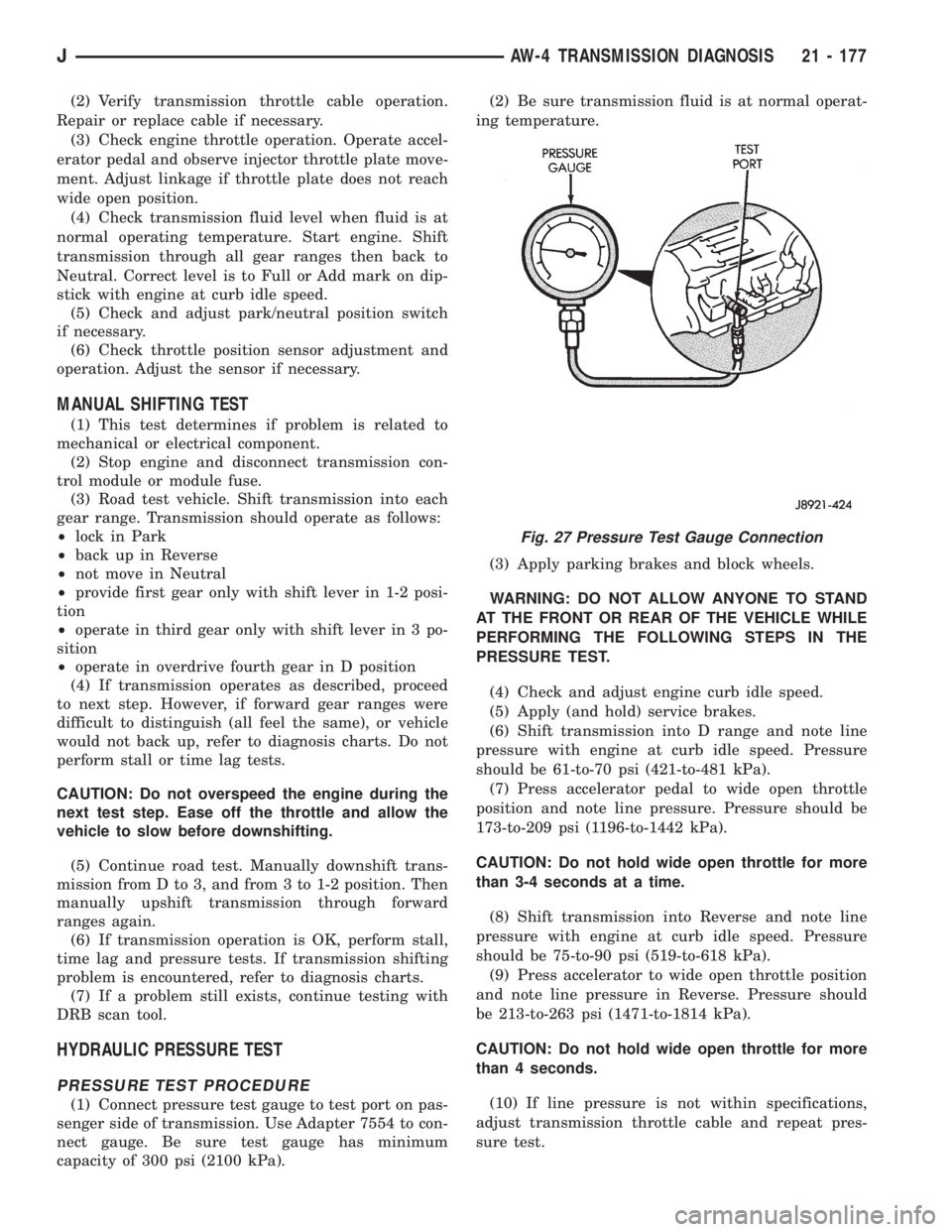
(1) Connect pressure test gauge to test port on pas-
senger side of transmission. Use Adapter 7554 to con-
nect gauge. Be sure test gauge has minimum
capacity of 300 psi (2100 kPa).(2) Be sure transmission fluid is at normal operat-
ing temperature.
(3) Apply parking brakes and block wheels.
WARNING: DO NOT ALLOW ANYONE TO STAND
AT THE FRONT OR REAR OF THE VEHICLE WHILE
PERFORMING THE FOLLOWING STEPS IN THE
PRESSURE TEST.
(4) Check and adjust engine curb idle speed.
(5) Apply (and hold) service brakes.
(6) Shift transmission into D range and note line
pressure with engine at curb idle speed. Pressure
should be 61-to-70 psi (421-to-481 kPa).
(7) Press accelerator pedal to wide open throttle
position and note line pressure. Pressure should be
173-to-209 psi (1196-to-1442 kPa).
CAUTION: Do not hold wide open throttle for more
than 3-4 seconds at a time.
(8) Shift transmission into Reverse and note line
pressure with engine at curb idle speed. Pressure
should be 75-to-90 psi (519-to-618 kPa).
(9) Press accelerator to wide open throttle position
and note line pressure in Reverse. Pressure should
be 213-to-263 psi (1471-to-1814 kPa).
CAUTION: Do not hold wide open throttle for more
than 4 seconds.
(10) If line pressure is not within specifications,
adjust transmission throttle cable and repeat pres-
sure test.
Fig. 27 Pressure Test Gauge Connection
JAW-4 TRANSMISSION DIAGNOSIS 21 - 177
Page 1995 of 2158
TRAILER HITCH
TRAILER HITCHÐXJ
CLASS III HITCH
A class III weight-distributing/equalizer type hitch
can be used to tow a trailer:
²Having a maximum gross weight of 5,000 lbs/2250
kg.
²Having a maximum tongue weight of 750 lbs/332
kg).
The following vehicle basic equipment is required
for class III trailer towing:
²P205/75R15 or larger tires.
²Full size spare tire.
²Trailer sway control.
²Trailer tow wire harness and connector.
²Heavy duty turn signal flasher element.
²Heavy duty axle (with synthetic lubricant).
²Heavy duty cooling system.
²Heavy duty generator/battery.
²Auxiliary automatic transmission fluid cooler.
²I-6, 4.0L engine.
Wide-angle type door mirrors are recommended but
not required.
WIRE HARNESS CONNECTORS
CLASS I HITCH CONNECTOR
The trailer tow wire harness connector for class I
trailer hitches is a 5-terminal, in-line type connector.
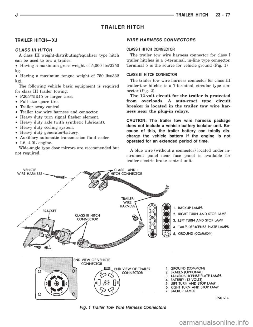
Terminal 5 is the source for vehicle ground (Fig. 1)
CLASS III HITCH CONNECTOR
The trailer tow wire harness connector for class III
trailer-tow hitches is a 7-terminal, circular type con-
nector (Fig. 2).
The 12-volt circuit for the trailer is protected
from overloads. A auto-reset type circuit
breaker is located in the trailer tow wire har-
ness near the plug-in relays.
CAUTION: The trailer tow wire harness package
does not include a vehicle battery isolator unit. Be-
cause of this, the trailer battery can totally dis-
charge the vehicle battery if the engine is not
operated for an extended period of time.
A blue wire (without a connector) located under in-
strument panel near fuse panel is available for
trailer electric brake control unit.
Fig. 1 Trailer Tow Wire Harness Connectors
JTRAILER HITCH 23 - 77
Page 2096 of 2158
off switch for battery voltage. If no voltage is present
test pressure cut-off switch. If voltage is present go
to next step.
(5) With ohmmeter test harness connector ground
circuit for continuity to ground. If circuit is open, (no
continuity) repair ground circuit. If circuit test OK
and clutch does not engage refer to Powertrain Diag-
nostic Service Manual for A/C clutch circuit test.
AIR CONDITIONING CONTROLSÐYJ VEHICLES
The air conditioning circuit consists of 3 segments;
battery supply, blower motor and compressor clutch.
The 3 segments have a common connection point at
the blower switch.
The power supply circuit extends from the HTR/
FAN fuse to the blower switch. From the blower
switch, battery feed is routed to the blower motor
and compressor clutch circuit.
Refer to Group 8W Wiring Diagrams for wiring
schematic and terminals. Use volt ohmmeter to test
switches.
COMPRESSOR CLUTCH
The clutch assembly consists of a stationary elec-
tromagnetic coil, hub bearing pulley assembly, and
clutch plate. When the coil is energized the plate is
magnetically engaged with the pulley and turns the
compressor shaft.
COMPRESSOR CLUTCH TEST
(1) Unplug clutch coil connector.
(2) Connect jumper wire from battery positive post
to clutch coil connector. The clutch should engage, if
not leave jumper wire connected and go to next step.
(3) Connect jumper wire from clutch coil frame to
chassis ground. The clutch should engage, if not re-
pair clutch coil ground or replace coil.
A/C COMPRESSOR CLUTCH RELAY
The A/C compressor clutch relay controls the 12-
volt source to the A/C clutch. The relay is activated
when the PCM receives a A/C request signal. The
PCM then sends a ground signal to the relay. The re-
lay is activated and sends 12-volts to the clutch coil
which energizes the clutch. The relay is located in
the power distribution center.
COMPRESSOR CLUTCH RELAY TEST
For test procedure refer to Powertrain Diagnostic
Service Manual for A/C clutch relay circuit test.
LOW-PRESSURE HIGH-PRESSURE CUT-OFF
SWITCH
The pressure cut-off switch is located on the filter
drier and is wired in series with compressor clutch.
The switch interrupts the power to the compressorclutch circuit when the pressure drops to 193 kPa (28
psi) or increases above 3100 to 3375 kPa (450 to 490
psi).
PRESSURE CUT-OFF SWITCH TEST
(1) Turn ignition switch to RUN, A/C blower switch
to ON and control set to MAX.
(2) Unplug pressure cut-off switch connector and
test feed circuit from the thermostatic, should be bat-
tery voltage. If not, proceed to thermostatic control
tests.
(3) Test for continuity between the switch termi-
nals. If continuity is not present recover refrigerant
system, replace switch, evacuate and recharge sys-
tem.
THERMOSTATIC CONTROL
Cycling of the compressor and therefore the tem-
perature of the outlet air is regulated by the thermo-
static control. A thermal sensor extends from the
control to the evaporator housing. When the temper-
ature of the evaporator drops below the set tempera-
ture, the thermostatic control opens the clutch
circuit. The circuit remains open until evaporator
temperature rises above the set temperature.
THERMOSTATIC CONTROL TEST
(1) Turn ignition switch to RUN, A/C blower switch
to ON and thermostatic control set to MAX cool.
(2) Test thermostatic control feed terminal from
blower switch, should be battery voltage. If not re-
pair open from blower switch.
(3) Test thermostatic control output terminal to
pressure cut-out switch, should be battery voltage. If
not, replace thermostatic control.
BLOWER MOTOR SWITCH
The blower switch controls blower motor speed.
The blower motor segment consists of the 3 wires
from the blower switch to the motor. Through the
switch, the 3 wires connect the motor brushes to bat-
tery supply. When connected to battery feed, the sep-
arate brushes provide the 3 blower speeds LO, MED,
and HIGH.
BLOWER MOTOR SWITCH TEST
(1) Turn ignition to RUN position.
(2) Test battery side of fuse for battery voltage. If
not, repair open from ignition switch.
(3) Test A/C blower switch feed circuit from fuse
box should be battery voltage. If not, repair open
from fuse panel.
(4) Test A/C blower switch LO terminal with
blower switch in LO, should be battery voltage. If
not, replace switch.
(5) Test A/C blower switch MED terminal with
blower switch in MED, should be battery voltage. If
not, replace switch.
24 - 16 HEATING AND AIR CONDITIONINGJ
Page 2097 of 2158
(6) Test A/C blower switch HIGH terminal with
blower switch in HIGH, should be battery voltage. If
not, replace switch.
BLOWER MOTOR
The A/C blower motor is attached to the evaporator
housing mounted under the instrument panel. The
motor has a ground wire and 3 wires connect to the
motor brushes. When voltage is applied to the sepa-
rate brushes it provides the 3 blower speeds LO,
MED, and HIGH.
BLOWER MOTOR TEST
Turn ignition switch to RUN for voltage tests and
turn ignition switch to OFF for resistance test.
(1) Test A/C blower motor ground terminal should
be 0 ohms. If not, repair ground circuit.
(2) Test A/C blower motor connector LO terminal
with blower switch in LO, should be battery voltage.
If not repair open from blower switch. If the blower
motor is still inoperative replace motor.
(3) Test A/C blower motor connector MED terminal
with blower switch in MED, should be battery volt-
age. If not repair open from blower switch. If the
blower motor is still inoperative replace motor.
(4) Test A/C blower motor connector HIGH termi-
nal with blower switch in HIGH, should be battery
voltage. If not, repair open from blower switch. If the
blower motor is still inoperative, replace motor.
HEATER DIAGNOSIS
On LHD XJ vehicles a water valve controls coolant
flow to the heater core. The valve is vacuum oper-
ated. When vacuum is applied, the valve opens and
coolant is directed through the heater core and back
to the engine. When the water valve is closed (no
vacuum applied) coolant flow bypasses the heater
core back to the engine.
The heating system receives its battery feed from
the fuse box. On YJ vehicles the feed circuit runs to
the HEATER/OFF switch and then to the BLOWER
switch. On XJ vehicles the feed circuit runs to the
HEAT/MODE switch and then to the BLOWER
switch.
The blower speed is controlled by the blower switch
and blower resistors. With the switch in LO, battery
voltage is supplied to the motor through all of the re-
sistors. The motor runs slowly. When the blower
switch is moved to a higher speed, battery voltage in-
creases to the blower motor which increase its speed.
This is accomplished by bypassing some of the blower
resistors. When the switch is in HI, blower resistors
are bypassed and battery voltage is applied directly
to the blower motor.
The following chart has been developed for quick
reference.
Refer to the Group 8W Wiring Diagrams for com-
plete wiring schematic.
JHEATING AND AIR CONDITIONING 24 - 17