1995 JEEP YJ fuse
[x] Cancel search: fusePage 931 of 2158
HEATED REAR WINDOW
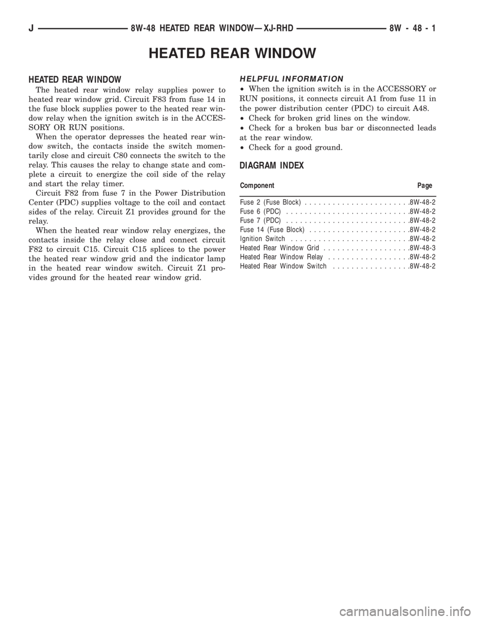
HEATED REAR WINDOW
The heated rear window relay supplies power to
heated rear window grid. Circuit F83 from fuse 14 in
the fuse block supplies power to the heated rear win-
dow relay when the ignition switch is in the ACCES-
SORY OR RUN positions.
When the operator depresses the heated rear win-
dow switch, the contacts inside the switch momen-
tarily close and circuit C80 connects the switch to the
relay. This causes the relay to change state and com-
plete a circuit to energize the coil side of the relay
and start the relay timer.
Circuit F82 from fuse 7 in the Power Distribution
Center (PDC) supplies voltage to the coil and contact
sides of the relay. Circuit Z1 provides ground for the
relay.
When the heated rear window relay energizes, the
contacts inside the relay close and connect circuit
F82 to circuit C15. Circuit C15 splices to the power
the heated rear window grid and the indicator lamp
in the heated rear window switch. Circuit Z1 pro-
vides ground for the heated rear window grid.
HELPFUL INFORMATION
²When the ignition switch is in the ACCESSORY or
RUN positions, it connects circuit A1 from fuse 11 in
the power distribution center (PDC) to circuit A48.
²Check for broken grid lines on the window.
²Check for a broken bus bar or disconnected leads
at the rear window.
²Check for a good ground.
DIAGRAM INDEX
Component Page
Fuse 2 (Fuse Block).......................8W-48-2
Fuse 6 (PDC)...........................8W-48-2
Fuse 7 (PDC)...........................8W-48-2
Fuse 14 (Fuse Block)......................8W-48-2
Ignition Switch..........................8W-48-2
Heated Rear Window Grid...................8W-48-3
Heated Rear Window Relay..................8W-48-2
Heated Rear Window Switch.................8W-48-2
J8W-48 HEATED REAR WINDOWÐXJ-RHD 8W - 48 - 1
Page 935 of 2158

OVERHEAD CONSOLE
OVERHEAD CONSOLE
When the ignition switch is in the START or RUN
position, it connects circuit A1 from fuse 6 in the
Power Distribution Center (PDC) to circuit A21. Cir-
cuit A21 supplies power to circuit F87 through fuse
26 in the fuse block. Circuit F87 supplies power to
the overhead console.
When the headlamps or parking lamps are ON, cir-
cuits L90 and E2 provide voltage to the overhead
console for illumination. Voltage on circuit L90 in-
forms the overhead console that the headlamps or
parking lamps are ON. Circuit E2 from the head
lamp switch powers the illumination lamps in the
overhead console. Circuit E2 also powers fuse 25 in
the fuse block.
Circuits Z1 and Z2 provides ground for the over-
head console. From circuit M2, the overhead console
senses when one of the door jamb switches opens.
AMBIENT TEMPERATURE SENSOR
The ambient temperature sensor is a variable re-
sistor. Circuit G31 supplies voltage from the over-
head console to the sensor. Circuit G32 is the signal
return from the sensor to the overhead console.
LAMPS
Circuit M1 supplies voltage for the case grounded
reading lamps in the overhead console. Fuse 16 in
the Power Distribution Center (PDC) supplies volt-
age to circuit M1 through circuit A7. Circuit A7 from
fuse 3 in the PDC supplies voltage to fuse 16 in the
PDC.
DIAGRAM INDEX
Component Page
Ambient Temperature Sensor.................8W-49-4
Chime/Buzzer Module......................8W-49-2
Fuse 3 (PDC)...........................8W-49-2
Fuse 5 (PDC)...........................8W-49-3
Fuse 6 (PDC)...........................8W-49-2
Fuse 9 (Fuse Block).......................8W-49-3
Fuse 16 (PDC)..........................8W-49-2
Fuse 26 (Fuse Block)......................8W-49-2
Headlamp Delay Module....................8W-49-2
Headlamp Switch.........................8W-49-3
Ignition Switch..........................8W-49-2
Instrument Cluster........................8W-49-4
Overhead Console....................8W-49-2, 3, 4
Telltale Connector (Instrument Cluster)...........8W-49-2
J8W-49 OVERHEAD CONSOLEÐXJ-RHD 8W - 49 - 1
Page 939 of 2158
FRONT LIGHTING
INDEX
page page
Diagram Index............................ 3
Dimming Module........................... 1
Fog Lamps............................... 2
Headlamp Delay Module..................... 1Headlamp Relay........................... 1
Headlamps............................... 1
Parking Lamps............................ 2
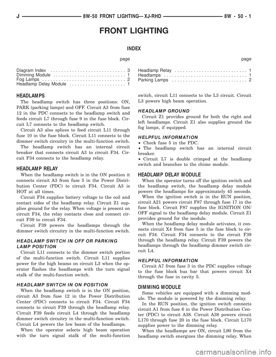
HEADLAMPS
The headlamp switch has three positions: ON,
PARK (parking lamps) and OFF. Circuit A3 from fuse
12 in the PDC connects to the headlamp switch and
feeds circuit L7 through fuse 9 in the fuse block. Cir-
cuit L7 connects to the headlamp switch.
Circuit A3 also splices to feed circuit L11 through
fuse 10 in the fuse block. Circuit L11 connects to the
dimmer switch circuitry in the multi-function switch.
The headlamp switch has an internal circuit
breaker that connects circuit A3 to circuit F34. Cir-
cuit F34 connects to the headlamp relay.
HEADLAMP RELAY
When the headlamp switch is in the ON position it
connects circuit A3 from fuse 5 in the Power Distri-
bution Center (PDC) to circuit F34. Circuit A3 is
HOT at all times.
Circuit F34 supplies battery voltage to the coil and
contact sides of the headlamp relay. Circuit Z1 sup-
plies ground for the relay. When voltage is present on
circuit F34, the relay contacts close and connect cir-
cuit F39 to circuit F34.
Circuit F39 powers the headlamps through the
dimmer switch circuitry in the multi-function switch.
HEADLAMP SWITCH IN OFF OR PARKING
LAMP POSITION
Circuit L11 connects to the dimmer switch portion
of the multi-function switch. Circuit L11 supplies
power for the high beams on circuit L3 when the op-
erator flashes the headlamps with the turn signal
stalk of the multi-function switch.
HEADLAMP SWITCH IN ON POSITION
When the headlamp switch is in the ON position,
circuit A3 from fuse 12 in the Power Distribution
Center (PDC) connects to circuit F34. Circuit F34
connects to circuit F39 through the headlamp relay.
Circuit F39 feeds circuit L4 through the headlamp
dimmer switch circuitry in the multi-function switch.
Circuit L4 powers the low beam of the headlamps.
When the operator selects high beam operation
with the turn signal stalk of the multi-functionswitch, circuit L11 connects to the L3 circuit. Circuit
L3 powers high beam operation.
HEADLAMP GROUND
Circuit Z1 provides ground for both the right and
left headlamps. Circuit Z1 also supplies ground the
fog lamps, if equipped.
HELPFUL INFORMATION
²Check fuse 5 in the PDC.
²The headlamp switch has an internal circuit
breaker.
²Circuit L7 is double crimped at the headlamp
switch and branches to the chime module.
HEADLAMP DELAY MODULE
When the operator turns off the ignition switch and
the headlamp switch, the headlamp delay module
powers the headlamps for approximately 45 seconds.
When the ignition switch is in the RUN position,
circuit A21 powers circuit F87 through fuse 17 in the
fuse block. Circuit F87 supplies the IGNITION ON/
OFF signal to the headlamp delay module. Circuit Z1
provides ground for the module.
When the headlamp delay module activates, it con-
nects circuit X4 from fuse 5 in the fuse block to cir-
cuit F34. Circuit F34 connects to the circuit F39
through the headlamp relay. Circuit F39 powers the
headlamps through the headlamp dimmer switch cir-
cuit L4.
HELPFUL INFORMATION
Circuit A7 from fuse 3 in the PDC supplies voltage
to the fuse block bus bar that powers circuit X4
through the fuse in cavity 5.
DIMMING MODULE
Some vehicles are equipped with a dimming mod-
ule. The module is powered by the dimming relay.
In the RUN position, the ignition switch connects
circuit A1 from fuse 6 in the Power Distribution Cen-
ter (PDC) to circuit A38. Circuit A38 powers circuit
L170 through fuse 20 in the fuse block. Circuit L170
supplies power to the dimming relay.
When the headlamps are ON, circuit L90 from the
headlamp switch energizes the dimming relay. When
J8W-50 FRONT LIGHTINGÐXJ-RHD 8W - 50 - 1
Page 940 of 2158
energized, the relay supplies power to the dimming
module on a branch of circuit A38. Circuit Z1 pro-
vides ground for the dimming relay.
The dimming module connects to the headlamp
dimmer switch on circuits L3 and L4.
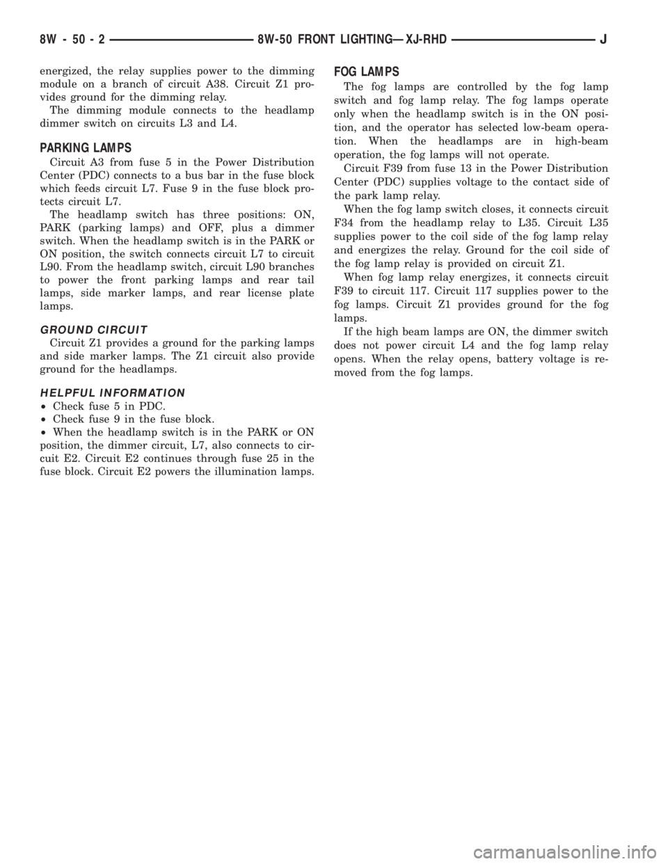
PARKING LAMPS
Circuit A3 from fuse 5 in the Power Distribution
Center (PDC) connects to a bus bar in the fuse block
which feeds circuit L7. Fuse 9 in the fuse block pro-
tects circuit L7.
The headlamp switch has three positions: ON,
PARK (parking lamps) and OFF, plus a dimmer
switch. When the headlamp switch is in the PARK or
ON position, the switch connects circuit L7 to circuit
L90. From the headlamp switch, circuit L90 branches
to power the front parking lamps and rear tail
lamps, side marker lamps, and rear license plate
lamps.
GROUND CIRCUIT
Circuit Z1 provides a ground for the parking lamps
and side marker lamps. The Z1 circuit also provide
ground for the headlamps.
HELPFUL INFORMATION
²Check fuse 5 in PDC.
²Check fuse 9 in the fuse block.
²When the headlamp switch is in the PARK or ON
position, the dimmer circuit, L7, also connects to cir-
cuit E2. Circuit E2 continues through fuse 25 in the
fuse block. Circuit E2 powers the illumination lamps.
FOG LAMPS
The fog lamps are controlled by the fog lamp
switch and fog lamp relay. The fog lamps operate
only when the headlamp switch is in the ON posi-
tion, and the operator has selected low-beam opera-
tion. When the headlamps are in high-beam
operation, the fog lamps will not operate.
Circuit F39 from fuse 13 in the Power Distribution
Center (PDC) supplies voltage to the contact side of
the park lamp relay.
When the fog lamp switch closes, it connects circuit
F34 from the headlamp relay to L35. Circuit L35
supplies power to the coil side of the fog lamp relay
and energizes the relay. Ground for the coil side of
the fog lamp relay is provided on circuit Z1.
When fog lamp relay energizes, it connects circuit
F39 to circuit 117. Circuit 117 supplies power to the
fog lamps. Circuit Z1 provides ground for the fog
lamps.
If the high beam lamps are ON, the dimmer switch
does not power circuit L4 and the fog lamp relay
opens. When the relay opens, battery voltage is re-
moved from the fog lamps.
8W - 50 - 2 8W-50 FRONT LIGHTINGÐXJ-RHDJ
Page 941 of 2158
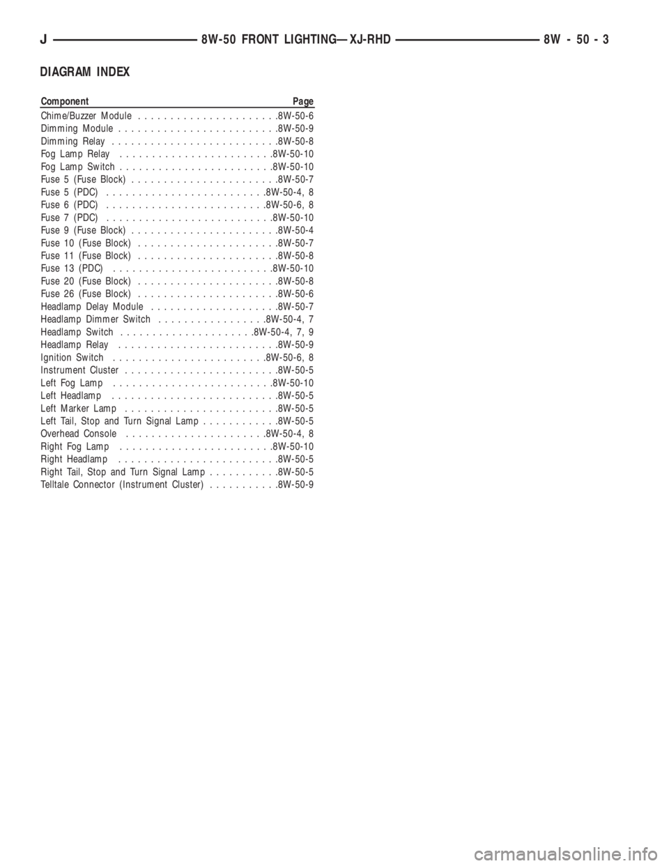
DIAGRAM INDEX
Component Page
Chime/Buzzer Module......................8W-50-6
Dimming Module.........................8W-50-9
Dimming Relay..........................8W-50-8
Fog Lamp Relay........................8W-50-10
Fog Lamp Switch........................8W-50-10
Fuse 5 (Fuse Block).......................8W-50-7
Fuse 5 (PDC).........................8W-50-4, 8
Fuse 6 (PDC).........................8W-50-6, 8
Fuse 7 (PDC)..........................8W-50-10
Fuse 9 (Fuse Block).......................8W-50-4
Fuse 10 (Fuse Block)......................8W-50-7
Fuse 11 (Fuse Block)......................8W-50-8
Fuse 13 (PDC).........................8W-50-10
Fuse 20 (Fuse Block)......................8W-50-8
Fuse 26 (Fuse Block)......................8W-50-6
Headlamp Delay Module....................8W-50-7
Headlamp Dimmer Switch.................8W-50-4, 7
Headlamp Switch.....................8W-50-4, 7, 9
Headlamp Relay.........................8W-50-9
Ignition Switch........................8W-50-6, 8
Instrument Cluster........................8W-50-5
Left Fog Lamp.........................8W-50-10
Left Headlamp..........................8W-50-5
Left Marker Lamp........................8W-50-5
Left Tail, Stop and Turn Signal Lamp............8W-50-5
Overhead Console......................8W-50-4, 8
Right Fog Lamp........................8W-50-10
Right Headlamp.........................8W-50-5
Right Tail, Stop and Turn Signal Lamp...........8W-50-5
Telltale Connector (Instrument Cluster)...........8W-50-9
J8W-50 FRONT LIGHTINGÐXJ-RHD 8W - 50 - 3
Page 949 of 2158
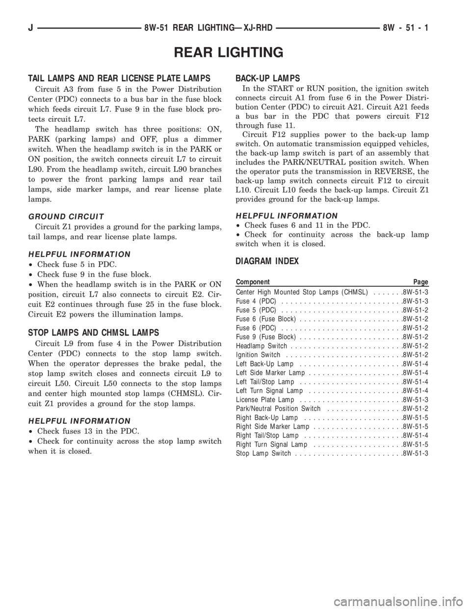
REAR LIGHTING
TAIL LAMPS AND REAR LICENSE PLATE LAMPS
Circuit A3 from fuse 5 in the Power Distribution
Center (PDC) connects to a bus bar in the fuse block
which feeds circuit L7. Fuse 9 in the fuse block pro-
tects circuit L7.
The headlamp switch has three positions: ON,
PARK (parking lamps) and OFF, plus a dimmer
switch. When the headlamp switch is in the PARK or
ON position, the switch connects circuit L7 to circuit
L90. From the headlamp switch, circuit L90 branches
to power the front parking lamps and rear tail
lamps, side marker lamps, and rear license plate
lamps.
GROUND CIRCUIT
Circuit Z1 provides a ground for the parking lamps,
tail lamps, and rear license plate lamps.
HELPFUL INFORMATION
²Check fuse 5 in PDC.
²Check fuse 9 in the fuse block.
²When the headlamp switch is in the PARK or ON
position, circuit L7 also connects to circuit E2. Cir-
cuit E2 continues through fuse 25 in the fuse block.
Circuit E2 powers the illumination lamps.
STOP LAMPS AND CHMSL LAMPS
Circuit L9 from fuse 4 in the Power Distribution
Center (PDC) connects to the stop lamp switch.
When the operator depresses the brake pedal, the
stop lamp switch closes and connects circuit L9 to
circuit L50. Circuit L50 connects to the stop lamps
and center high mounted stop lamps (CHMSL). Cir-
cuit Z1 provides a ground for the stop lamps.
HELPFUL INFORMATION
²Check fuses 13 in the PDC.
²Check for continuity across the stop lamp switch
when it is closed.
BACK-UP LAMPS
In the START or RUN position, the ignition switch
connects circuit A1 from fuse 6 in the Power Distri-
bution Center (PDC) to circuit A21. Circuit A21 feeds
a bus bar in the PDC that powers circuit F12
through fuse 11.
Circuit F12 supplies power to the back-up lamp
switch. On automatic transmission equipped vehicles,
the back-up lamp switch is part of an assembly that
includes the PARK/NEUTRAL position switch. When
the operator puts the transmission in REVERSE, the
back-up lamp switch connects circuit F12 to circuit
L10. Circuit L10 feeds the back-up lamps. Circuit Z1
provides ground for the back-up lamps.
HELPFUL INFORMATION
²Check fuses 6 and 11 in the PDC.
²Check for continuity across the back-up lamp
switch when it is closed.
DIAGRAM INDEX
Component Page
Center High Mounted Stop Lamps (CHMSL).......8W-51-3
Fuse 4 (PDC)...........................8W-51-3
Fuse 5 (PDC)...........................8W-51-2
Fuse 6 (Fuse Block).......................8W-51-2
Fuse 6 (PDC)...........................8W-51-2
Fuse 9 (Fuse Block).......................8W-51-2
Headlamp Switch.........................8W-51-2
Ignition Switch..........................8W-51-2
Left Back-Up Lamp.......................8W-51-4
Left Side Marker Lamp.....................8W-51-4
Left Tail/Stop Lamp.......................8W-51-4
Left Turn Signal Lamp.....................8W-51-4
License Plate Lamp.......................8W-51-3
Park/Neutral Position Switch.................8W-51-2
Right Back-Up Lamp......................8W-51-5
Right Side Marker Lamp....................8W-51-5
Right Tail/Stop Lamp......................8W-51-4
Right Turn Signal Lamp....................8W-51-5
Stop Lamp Switch........................8W-51-3
J8W-51 REAR LIGHTINGÐXJ-RHD 8W - 51 - 1
Page 955 of 2158
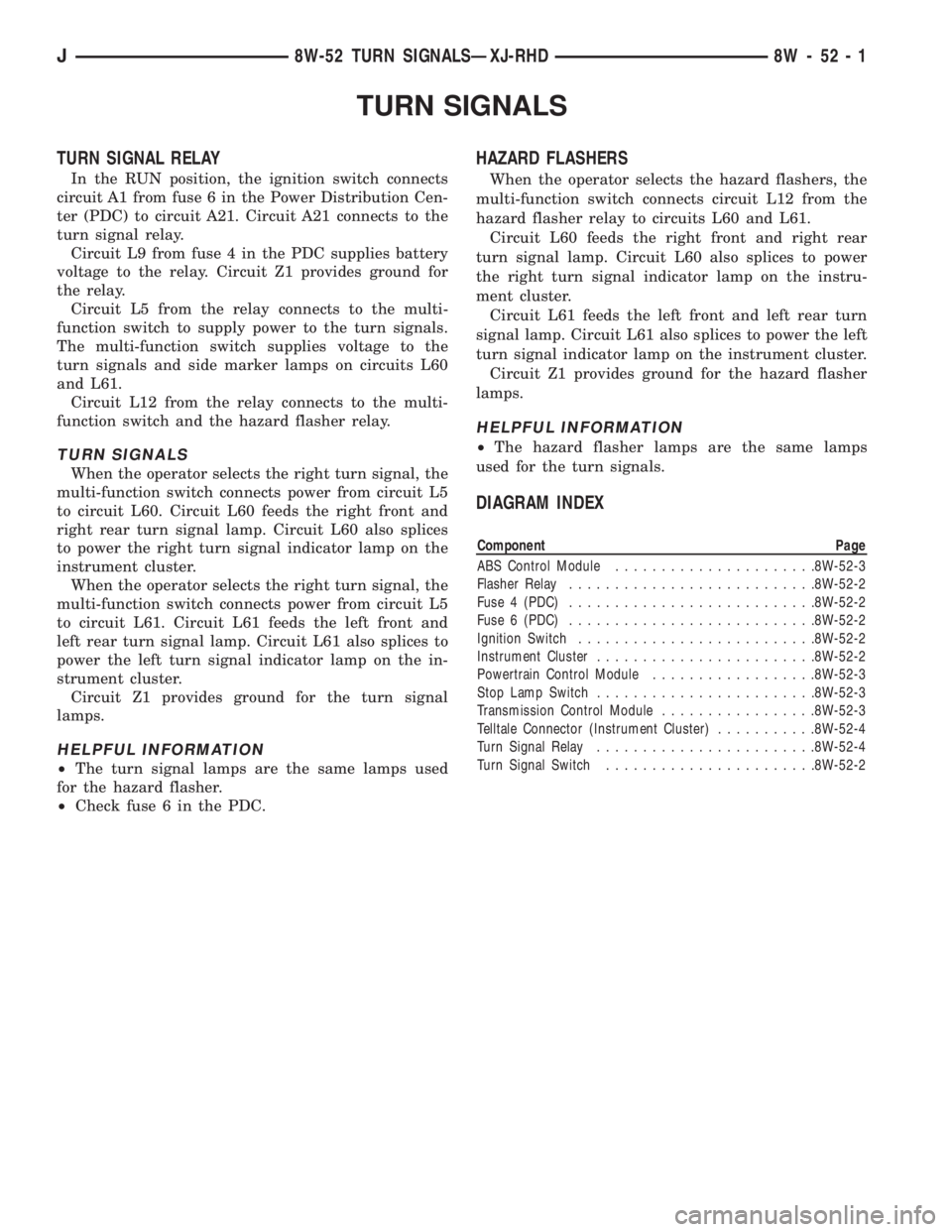
TURN SIGNALS
TURN SIGNAL RELAY
In the RUN position, the ignition switch connects
circuit A1 from fuse 6 in the Power Distribution Cen-
ter (PDC) to circuit A21. Circuit A21 connects to the
turn signal relay.
Circuit L9 from fuse 4 in the PDC supplies battery
voltage to the relay. Circuit Z1 provides ground for
the relay.
Circuit L5 from the relay connects to the multi-
function switch to supply power to the turn signals.
The multi-function switch supplies voltage to the
turn signals and side marker lamps on circuits L60
and L61.
Circuit L12 from the relay connects to the multi-
function switch and the hazard flasher relay.
TURN SIGNALS
When the operator selects the right turn signal, the
multi-function switch connects power from circuit L5
to circuit L60. Circuit L60 feeds the right front and
right rear turn signal lamp. Circuit L60 also splices
to power the right turn signal indicator lamp on the
instrument cluster.
When the operator selects the right turn signal, the
multi-function switch connects power from circuit L5
to circuit L61. Circuit L61 feeds the left front and
left rear turn signal lamp. Circuit L61 also splices to
power the left turn signal indicator lamp on the in-
strument cluster.
Circuit Z1 provides ground for the turn signal
lamps.
HELPFUL INFORMATION
²The turn signal lamps are the same lamps used
for the hazard flasher.
²Check fuse 6 in the PDC.
HAZARD FLASHERS
When the operator selects the hazard flashers, the
multi-function switch connects circuit L12 from the
hazard flasher relay to circuits L60 and L61.
Circuit L60 feeds the right front and right rear
turn signal lamp. Circuit L60 also splices to power
the right turn signal indicator lamp on the instru-
ment cluster.
Circuit L61 feeds the left front and left rear turn
signal lamp. Circuit L61 also splices to power the left
turn signal indicator lamp on the instrument cluster.
Circuit Z1 provides ground for the hazard flasher
lamps.
HELPFUL INFORMATION
²The hazard flasher lamps are the same lamps
used for the turn signals.
DIAGRAM INDEX
Component Page
ABS Control Module......................8W-52-3
Flasher Relay...........................8W-52-2
Fuse 4 (PDC)...........................8W-52-2
Fuse 6 (PDC)...........................8W-52-2
Ignition Switch..........................8W-52-2
Instrument Cluster........................8W-52-2
Powertrain Control Module..................8W-52-3
Stop Lamp Switch........................8W-52-3
Transmission Control Module.................8W-52-3
Telltale Connector (Instrument Cluster)...........8W-52-4
Turn Signal Relay........................8W-52-4
Turn Signal Switch.......................8W-52-2
J8W-52 TURN SIGNALSÐXJ-RHD 8W - 52 - 1
Page 960 of 2158
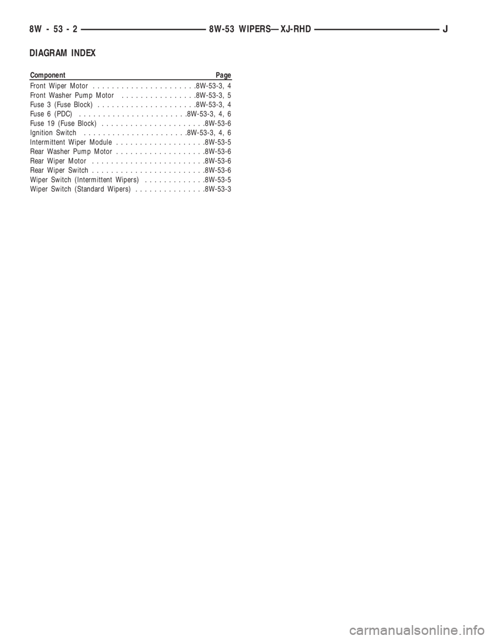
DIAGRAM INDEX
Component Page
Front Wiper Motor......................8W-53-3, 4
Front Washer Pump Motor................8W-53-3, 5
Fuse 3 (Fuse Block).....................8W-53-3, 4
Fuse 6 (PDC).......................8W-53-3, 4, 6
Fuse 19 (Fuse Block)......................8W-53-6
Ignition Switch......................8W-53-3, 4, 6
Intermittent Wiper Module...................8W-53-5
Rear Washer Pump Motor...................8W-53-6
Rear Wiper Motor........................8W-53-6
Rear Wiper Switch........................8W-53-6
Wiper Switch (Intermittent Wipers).............8W-53-5
Wiper Switch (Standard Wipers)...............8W-53-3
8W - 53 - 2 8W-53 WIPERSÐXJ-RHDJ