1995 JEEP YJ engine coolant
[x] Cancel search: engine coolantPage 2106 of 2158
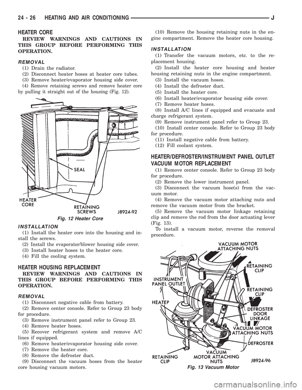
HEATER CORE
REVIEW WARNINGS AND CAUTIONS IN
THIS GROUP BEFORE PERFORMING THIS
OPERATION.
REMOVAL
(1) Drain the radiator.
(2) Disconnect heater hoses at heater core tubes.
(3) Remove heater/evaporator housing side cover.
(4) Remove retaining screws and remove heater core
by pulling it straight out of the housing (Fig. 12).
INSTALLATION
(1) Install the heater core into the housing and in-
stall the screws.
(2) Install the evaporator/blower housing side cover.
(3) Install heater hoses to the heater core.
(4) Fill the cooling system.
HEATER HOUSING REPLACEMENT
REVIEW WARNINGS AND CAUTIONS IN
THIS GROUP BEFORE PERFORMING THIS
OPERATION.
REMOVAL
(1) Disconnect negative cable from battery.
(2) Remove center console. Refer to Group 23 body
for procedure.
(3) Remove instrument panel refer to Group 23.
(4) Remove heater hoses.
(5) Recover refrigerant system and remove A/C
lines if equipped.
(6) Remove heater/evaporator housing side cover.
(7) Remove the heater core.
(8) Remove the defroster duct.
(9) Disconnect the vacuum hoses from the heater
core housing vacuum motors.(10) Remove the housing retaining nuts in the en-
gine compartment. Remove the heater core housing.
INSTALLATION
(1) Transfer the vacuum motors, etc. to the re-
placement housing.
(2) Install the heater core housing and heater
housing retaining nuts in the engine compartment.
(3) Install the vacuum hoses.
(4) Install the defroster duct.
(5) Install the heater core.
(6) Install heater/evaporator housing side cover.
(7) Remove heater hoses.
(8) Install A/C lines if equipped and evacuate and
charge refrigerant system.
(9) Remove instrument panel refer to Group 23.
(10) Install center console. Refer to Group 23 body
for procedure.
(11) Install negative cable from battery.
(12) Fill coolant system.
HEATER/DEFROSTER/INSTRUMENT PANEL OUTLET
VACUUM MOTOR REPLACEMENT
(1) Remove center console. Refer to Group 23 body
for procedure.
(2) Remove the lower instrument panel.
(3) Disconnect the vacuum hose(s) from the vac-
uum motor.
(4) Remove the vacuum motor attaching nuts and
remove the vacuum motor from the bracket.
(5) Remove the vacuum motor linkage retaining
clip and remove the rod from the door actuating lever
(Fig. 13).
To install a vacuum motor, reverse the removal
procedure.
Fig. 12 Heater Core
Fig. 13 Vacuum Motor
24 - 26 HEATING AND AIR CONDITIONINGJ
Page 2108 of 2158
(4) Plug the harness into the low pressure switch
(Fig. 16).
(5) Connect the A/C hoses to the condenser.
(6) Connect the transmission cooler lines (if
equipped with automatic transmission).
(7) Connect the fan shroud and the radiator hoses.
(8) Fill coolant system (Refer to cooling for proper
procedure).
(9) Evacuate and charge the A/C system.
CONDENSERÐ4.0L ENGINES
REVIEW WARNINGS AND CAUTIONS IN
THIS GROUP BEFORE PERFORMING THIS
OPERATION.
REMOVAL
(1) Recover refrigerant from the system.
(2) Remove the upper radiator support.
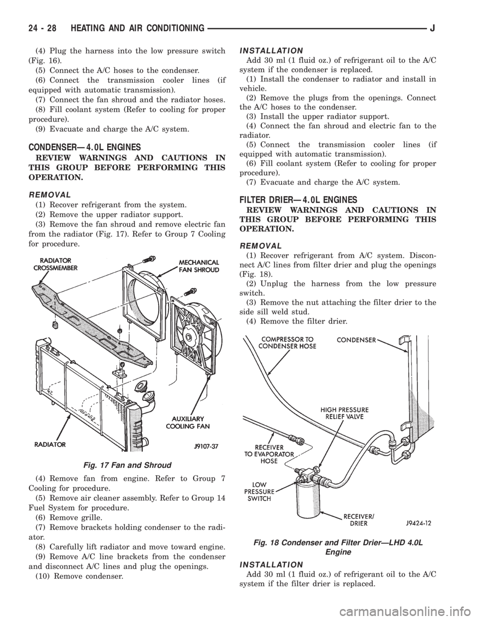
(3) Remove the fan shroud and remove electric fan
from the radiator (Fig. 17). Refer to Group 7 Cooling
for procedure.
(4) Remove fan from engine. Refer to Group 7
Cooling for procedure.
(5) Remove air cleaner assembly. Refer to Group 14
Fuel System for procedure.
(6) Remove grille.
(7) Remove brackets holding condenser to the radi-
ator.
(8) Carefully lift radiator and move toward engine.
(9) Remove A/C line brackets from the condenser
and disconnect A/C lines and plug the openings.
(10) Remove condenser.
INSTALLATION
Add 30 ml (1 fluid oz.) of refrigerant oil to the A/C
system if the condenser is replaced.
(1) Install the condenser to radiator and install in
vehicle.
(2) Remove the plugs from the openings. Connect
the A/C hoses to the condenser.
(3) Install the upper radiator support.
(4) Connect the fan shroud and electric fan to the
radiator.
(5) Connect the transmission cooler lines (if
equipped with automatic transmission).
(6) Fill coolant system (Refer to cooling for proper
procedure).
(7) Evacuate and charge the A/C system.
FILTER DRIERÐ4.0L ENGINES
REVIEW WARNINGS AND CAUTIONS IN
THIS GROUP BEFORE PERFORMING THIS
OPERATION.
REMOVAL
(1) Recover refrigerant from A/C system. Discon-
nect A/C lines from filter drier and plug the openings
(Fig. 18).
(2) Unplug the harness from the low pressure
switch.
(3) Remove the nut attaching the filter drier to the
side sill weld stud.
(4) Remove the filter drier.
INSTALLATION
Add 30 ml (1 fluid oz.) of refrigerant oil to the A/C
system if the filter drier is replaced.
Fig. 17 Fan and Shroud
Fig. 18 Condenser and Filter DrierÐLHD 4.0L
Engine
24 - 28 HEATING AND AIR CONDITIONINGJ
Page 2113 of 2158
INSTALLATION
(1) Install the cables to the heater control panel.
(2) Connect right vent door cable. DO NOT connect
the left door cable at this time.
(3) Open and close the right vent door (one time)
using the air control lever on the heater control
panel.
(4) Connect left vent door cable.
(5) Open and close both vent doors with the air
control lever. Verify that both vent doors open at the
same time.
HEATER CORE AND HOUSING
REVIEW ALL WARNINGS AND CAUTIONS IN
THIS GROUP BEFORE PERFORMING THIS
OPERATION.
REMOVAL
(1) Drain coolant from the radiator.
(2) Disconnect heater hoses.
(3) Disconnect vent door cables.
(4) Disconnect blower motor wire.
(5) Disconnect defroster duct.
(6) Remove nuts that attach the heater housing
studs to the engine compartment side of the dash
panel.
(7) Remove heater housing assembly by tilting it
downward, to disengage it from the defroster duct.
Pull it rearward and out from under the instrument
panel.
(8) Remove heater hosing cover from the housing.
(9) Remove heater core from the housing.
INSTALLATION
(1) Install the heater core into the housing and in-
stall the cover on the housing.
(2) Position heater housing on the dash panel. Be
sure the housing studs all extend through the dash
panel.
(3) Install the seals on the heater core outlet and
inlet tubes and over the blower motor housing.
(4) Install attaching nuts on the housing studs.
CAUTION: DO NOT over tighten the attaching nuts.
The housing could become distorted causing air
leaks and improper heater door operation. Tighten
the nuts alternately and evenly until 2 stud threads
are visible beyond each nut.
(5) Connect defroster duct to the housing.
(6) Connect blower motor wire.
(7) Connect vent door control cables.
(8) Connect heater hoses.
(9) Fill cooling system.
(10) Check system operation.
BLOWER MOTOR (HEATING)
REMOVAL
(1) Remove heater housing.
(2) Remove blower motor-to-heater housing attach-
ing screws/nuts.
(3) Remove blower motor from the housing.
INSTALLATION
(1) Position blower motor into housing.
(2) Install and tighten blower motor-to-heater
housing attaching screws/nuts.
(3) Install heater housing.
(4) Check blower motor and heater operation.
DEFROSTER NOZZLE AND DUCT
REVIEW ALL WARNINGS AND CAUTIONS IN
THIS GROUP BEFORE PERFORMING THIS
OPERATION.
REMOVAL
(1) Drain coolant from the radiator.
(2) Disconnect heater hoses.
(3) Remove nuts attaching the heater housing
studs to the engine compartment side of the dash
panel.
(4) Disconnect speedometer cable.
(5) Remove glove box.
(6) Tilt heater housing back and pull it rearward
and out from under the instrument panel.
(7) Disconnect vent control cables.
(8) Remove fresh air intake grille from the cowl.
(9) Remove fresh air intake duct.
(10) Lower windshield.
(11) Remove defroster nozzle attaching screws and
remove the nozzle and duct.
INSTALLATION
(1) Install defroster nozzle and duct.
(2) Raise and secure the windshield.
(3) Install fresh air intake duct.
(4) Install fresh air intake grille on the cowl.
(5) Install vent cables.
(6) Position heater housing on the dash panel. Be
sure all the housing studs extend through the dash
panel.
(7) Install seals on the blower motor and heater
core inlet and outlet tubes.
(8) Install on the housing studs.
CAUTION: DO NOT over tighten the attaching nuts.
The housing could become distorted causing air
leaks and improper heater door operation. Tighten
the nuts alternately and evenly until 2 stud threads
are visible beyond each nut.
(9) Install glove box.
(10) Connect speedometer cable.
JHEATING AND AIR CONDITIONING 24 - 33
Page 2114 of 2158
(11) Connect the heater hoses.
(12) Fill cooling system.
FRESH AIR DOOR VACUUM MOTOR
REMOVAL
(1) Remove glove box and assist handle.
(2) Disconnect vacuum hose from the motor.
(3) Remove motor lever retaining clip.
(4) Remove motor attaching nuts and remove the
motor from the fresh air duct.
INSTALLATION
(1) Position motor on fresh air duct and install the
motor attaching nuts.
(2) Align motor lever with the air door lever and
install the lever retaining clip.
(3) Connect vacuum hose to the motor.
(4) Install glove box and assist handle.
FRESH AIR INTAKE DUCT
REVIEW WARNINGS AND CAUTIONS IN
THIS GROUP BEFORE PERFORMING THIS
OPERATION.
REMOVAL
(1) Drain coolant from the radiator.
(2) Disconnect heater hoses.
(3) Remove nuts attaching the heater housing
studs to the dash panel from inside the engine com-
partment.
(4) Disconnect speedometer cable.
(5) Remove glove box and assist handle.
(6) Tilt heater housing back and pull it rearward
and out from under the instrument panel.
(7) Disconnect vent cables.
(8) Remove windshield bracket bolts and lower
windshield.
(9) Remove fresh air intake grille from the cowl.
(10) Remove fresh air intake duct.
INSTALLATION
(1) Install fresh air intake duct.
(2) Install defroster nozzle and duct.
(3) Raise and secure the windshield.
(4) Install fresh air grille on the cowl.
(5) Install vent cables.
(6) Position heater housing on the dash panel. Be
sure all the housing studs extend through the dash
panel.
(7) Install seals on the blower motor and heater
core inlet and outlet tubes.
(8) Install nuts on the heater housing studs.
CAUTION: DO NOT over tighten the attaching nuts.
The housing could become distorted causing air
leaks and improper heater door operation. Tightenthe nuts alternately and evenly until 2 stud threads
are visible beyond each nut.
(9) Install glove box and assist handle.
(10) Connect speedometer cable.
(11) Connect heater hoses.
(12) Fill cooling system.
TEMPERATURE CONTROL THERMOSTAT
REMOVAL
(1) Remove mounting bolts and lower the evapora-
tor housing.
(2) Remove the attaching screws holding the top
and bottom housings together.
(3) Separate the housings.
(4) Remove the thermostat.
INSTALLATION
(1) Install temperature control thermostat. Insert
thermostat capillary tube into the evaporator coil a
minimum of 50 mm (2 inch).
CAUTION: Handle the tube with care to avoid bends
or kinks that could cause the thermostat to mal-
function.
(2) Assemble the housing and install the attaching
screws. DO NOT over tighten the attaching screws.
(3) Install the evaporator housing.
A/C CONDENSER
REVIEW WARNINGS AND CAUTIONS IN
THIS GROUP BEFORE PERFORMING THIS
OPERATION.
REMOVAL
(1) Recover refrigerant from A/C system.
(2) Drain the radiator.
(3) Remove fan shroud and radiator.
(4) Disconnect A/C line from the condenser.
(5) Remove condenser attaching screws and tilt the
bottom of the condenser toward the engine.Plug all
the condenser openings to prevent entry of dirt
or moisture.
(6) Working from under the vehicle, disconnect the
receiver-drier to-evaporator hose fitting from the re-
ceiver-drier.
(7) Remove condenser and receiver-drier as an as-
sembly.
(8) Remove receiver-drier from the condenser, if
necessary.
INSTALLATION
Add 30 ml (1 fluid oz.) of refrigerant oil to the A/C
system if the condenser is replaced.
(1) Attach receiver-drier to the condenser.
(2) Install condenser and connect A/C line to the
receiver-drier.
24 - 34 HEATING AND AIR CONDITIONINGJ
Page 2115 of 2158
(3) Install condenser attaching screws.
(4) Connect condenser A/C line.
(5) Install radiator and fan shroud.
(6) Fill coolant system (Refer to cooling for proper
procedure).
(7) Evacuate, charge and leak test the air condi-
tioning system.
RECEIVER-DRIER REPLACEMENT
REVIEW ALL WARNINGS AND CAUTIONS IN
THIS GROUP BEFORE PERFORMING THIS
OPERATION.
REMOVAL
(1) Recover refrigerant from A/C system.
(2) Disconnect A/C lines from the receiver-drier.
(3) Remove receiver-drier attaching screws and re-
move receiver-drier.
INSTALLATION
(1) Position receiver-drier in place and install re-
ceiver-drier attaching screws.
(2) Connect A/C lines to receiver-drier.
(3) Evacuate, charge and leak test the air condi-
tioning system.
EVAPORATOR AND HOUSING
REVIEW ALL WARNINGS AND CAUTIONS IN
THIS GROUP BEFORE PERFORMING THIS
OPERATION.
REMOVAL
(1) Recover refrigerant from A/C system.
(2) Disconnect A/C lines.
(3) Remove hose clamps and dash grommet retain-
ing screws.
(4) Remove the evaporator housing-to-instrument
panel attaching screws and the housing mounting
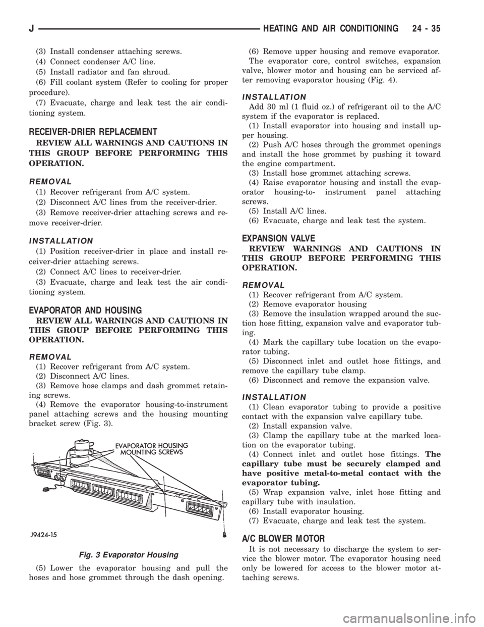
bracket screw (Fig. 3).
(5) Lower the evaporator housing and pull the
hoses and hose grommet through the dash opening.(6) Remove upper housing and remove evaporator.
The evaporator core, control switches, expansion
valve, blower motor and housing can be serviced af-
ter removing evaporator housing (Fig. 4).
INSTALLATION
Add 30 ml (1 fluid oz.) of refrigerant oil to the A/C
system if the evaporator is replaced.
(1) Install evaporator into housing and install up-
per housing.
(2) Push A/C hoses through the grommet openings
and install the hose grommet by pushing it toward
the engine compartment.
(3) Install hose grommet attaching screws.
(4) Raise evaporator housing and install the evap-
orator housing-to- instrument panel attaching
screws.
(5) Install A/C lines.
(6) Evacuate, charge and leak test the system.
EXPANSION VALVE
REVIEW WARNINGS AND CAUTIONS IN
THIS GROUP BEFORE PERFORMING THIS
OPERATION.
REMOVAL
(1) Recover refrigerant from A/C system.
(2) Remove evaporator housing
(3) Remove the insulation wrapped around the suc-
tion hose fitting, expansion valve and evaporator tub-
ing.
(4) Mark the capillary tube location on the evapo-
rator tubing.
(5) Disconnect inlet and outlet hose fittings, and
remove the capillary tube clamp.
(6) Disconnect and remove the expansion valve.
INSTALLATION
(1) Clean evaporator tubing to provide a positive
contact with the expansion valve capillary tube.
(2) Install expansion valve.
(3) Clamp the capillary tube at the marked loca-
tion on the evaporator tubing.
(4) Connect inlet and outlet hose fittings.The
capillary tube must be securely clamped and
have positive metal-to-metal contact with the
evaporator tubing.
(5) Wrap expansion valve, inlet hose fitting and
capillary tube with insulation.
(6) Install evaporator housing.
(7) Evacuate, charge and leak test the system.
A/C BLOWER MOTOR
It is not necessary to discharge the system to ser-
vice the blower motor. The evaporator housing need
only be lowered for access to the blower motor at-
taching screws.Fig. 3 Evaporator Housing
JHEATING AND AIR CONDITIONING 24 - 35
Page 2124 of 2158
COMPONENT REMOVAL/INSTALLATION
INDEX
page page
Air Cleaner Element........................ 7
Coolant Temperature Sensor.................. 7
EVAP Canister............................ 7
Fuel Tank Filler Tube Cap.................... 7Oxygen (O2S) Sensor....................... 7
Powertrain Control Module (PCM).............. 7
Pressure Relief/Rollover Valve................. 7
AIR CLEANER ELEMENT
For removal and installation procedures of both the
air cleaner housing and the air cleaner element, refer
to the Group 14, Fuel System.
COOLANT TEMPERATURE SENSOR
For description, operation, diagnosis and removal/
installation procedures of the engine coolant temper-
ature sensor, refer to Group 14, Fuel Systems.
EVAP CANISTER
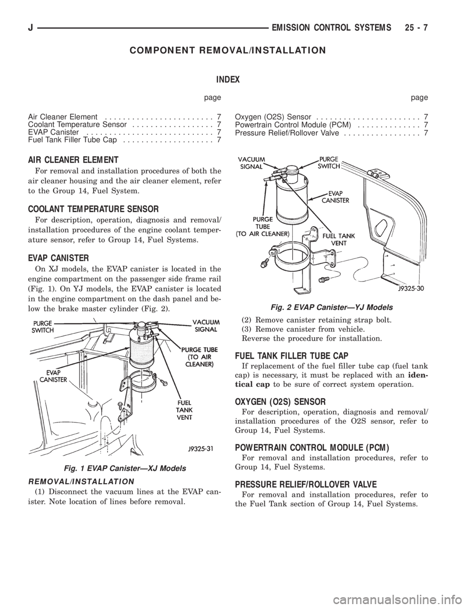
On XJ models, the EVAP canister is located in the
engine compartment on the passenger side frame rail
(Fig. 1). On YJ models, the EVAP canister is located
in the engine compartment on the dash panel and be-
low the brake master cylinder (Fig. 2).
REMOVAL/INSTALLATION
(1) Disconnect the vacuum lines at the EVAP can-
ister. Note location of lines before removal.(2) Remove canister retaining strap bolt.
(3) Remove canister from vehicle.
Reverse the procedure for installation.
FUEL TANK FILLER TUBE CAP
If replacement of the fuel filler tube cap (fuel tank
cap) is necessary, it must be replaced with aniden-
tical capto be sure of correct system operation.
OXYGEN (O2S) SENSOR
For description, operation, diagnosis and removal/
installation procedures of the O2S sensor, refer to
Group 14, Fuel Systems.
POWERTRAIN CONTROL MODULE (PCM)
For removal and installation procedures, refer to
Group 14, Fuel Systems.
PRESSURE RELIEF/ROLLOVER VALVE
For removal and installation procedures, refer to
the Fuel Tank section of Group 14, Fuel Systems.
Fig. 1 EVAP CanisterÐXJ Models
Fig. 2 EVAP CanisterÐYJ Models
JEMISSION CONTROL SYSTEMS 25 - 7
Page 2125 of 2158
- XJ, ANTENNA REMOVE/INSTALL........8F-8
- XJ, GENERAL INFORMATION...........8K-1
- XJ, MULTI-FUNCTION SWITCH..........8J-4
- XJ, MULTI-FUNCTION SWITCH
REMOVE/INSTALL.....................8J-5
- XJ, RADIO REMOVE/INSTALL...........8F-6
- XJ, SOUND BAR REMOVE/INSTALL......8F-8
- XJ, SPEAKERS REMOVE/INSTALL........8F-6
- XJ, TURN SIGNAL/HAZARD WARNING
SYSTEM.............................8J-3
- YJ, ANTENNA REMOVE/INSTALL.......8F-10
- YJ, BUZZER MODULE SCHEMATIC......8U-4
- YJ, GENERAL INFORMATION..........8K-10
- YJ, HAZARD WARNING SYSTEM........8J-4
- YJ, RADIO REMOVE/INSTALL...........8F-9
- YJ, SERVICE PROCEDURES...........8K-17
- YJ, SOUND BAR REMOVE/INSTALL.....8F-10
- YJ, SPEAKERS REMOVE/INSTALL........8F-9
- YJ, TURN SIGNAL SYSTEM............8J-3
- YJ, TURN SIGNAL/HAZARD WARNING
SWITCH REMOVE/INSTALL..............8J-5
30RH/32RH AUTOMATIC TRANSMISSION . . 21-67
30RH/32RH GENERAL SPECIFICATIONS . . 21-335
30RH/32RH IN-VEHICLE SERVICE........21-99
30RH/32RH PRESSURE TEST
SPECIFICATIONS....................21-336
30RH/32RH TORQUE SPECIFICATIONS . . . 21-336
30RH/32RH TRANSMISSION DIAGNOSIS . . 21-70
30RH/32RH TRANSMISSION OVERHAUL . 21-119
30RH/32RH TRANSMISSION REMOVAL
AND INSTALLATION..................21-115
4-CYLINDER ENGINE, ENGINE FIRING
ORDERÐ2.5L.......................8D-32
60-WAY CONNECTOR, POWERTRAIN
CONTROL MODULE (PCM).............14-40
6-CYLINDER ENGINE, AUXILIARY
ELECTRIC COOLING FANÐXJ MODELS
WITH 4.0L...........................7-35
6-CYLINDER ENGINE, ENGINE FIRING
ORDERÐ4.0L.......................8D-32
ABS BRAKE DIAGNOSIS.................5-3
ABS COMPONENT SERVICEABILITY.......5-37
ABS DIAGNOSTIC CONNECTOR.......5-35,5-3
ABS OPERATION AND SERVICE..........5-33
ABS POWER RELAY; ANTI-LOCK BRAKES
(XJ).............................8W-32-1
ABS POWER RELAY; ANTI-LOCK BRAKES
(XJ-RHD).........................8W-32-1
ABS POWER RELAY; ANTI-LOCK BRAKES
(YJ).............................8W-32-1
ABS PUMP MOTOR RELAY; ANTI-LOCK
BRAKES (XJ)......................8W-32-1
ABS PUMP MOTOR RELAY; ANTI-LOCK
BRAKES (XJ-RHD).................8W-32-1
ABS PUMP MOTOR RELAY; ANTI-LOCK
BRAKES (YJ)......................8W-32-1
ABS SYSTEM POWER-UP AND
INITIALIZATION.......................5-35
ABS WARNING LAMP; ANTI-LOCK
BRAKES (XJ)......................8W-32-2
ABS WARNING LAMP; ANTI-LOCK
BRAKES (XJ-RHD).................8W-32-2
ABS WARNING LAMP; ANTI-LOCK
BRAKES (YJ)
......................8W-32-2
ABS WARNING LAMP; INSTRUMENT
CLUSTER (XJ)
.....................8W-40-2
ABS WARNING LAMP; INSTRUMENT
CLUSTER (XJ-RHD)
................8W-40-2
ABS WARNING LAMP; INSTRUMENT
CLUSTER (YJ)
.....................8W-40-2
ABS WARNING LIGHT DISPLAY
...........5-3
ABSOLUTE PRESSURE (MAP) SENSOR,
MANIFOLD; FUEL SYSTEM
.............14-63
ABSOLUTE PRESSURE (MAP) SENSOR,
MANIFOLD; FUEL/IGNITION (YJ)
......8W-30-4
ABSOLUTE PRESSURE (MAP) SENSOR,
MANIFOLD; IGNITION SYSTEMS
....8D-23,8D-5
ABSOLUTE PRESSURE (MAP) SENSOR
TEST, MANIFOLD; FUEL SYSTEM
........14-47
ABSOLUTE PRESSURE (MAP) SENSOR
TEST, MANIFOLD; IGNITION SYSTEMS
....8D-11
ABSOLUTE PRESSURE (MAP)
SENSORÐPCM INPUT, MANIFOLD
.......14-23
ABSOLUTE PRESSURE SENSOR,
MANIFOLD; FUEL/IGNITION (XJ)
......8W-30-4
ABSOLUTE PRESSURE SENSOR,
MANIFOLD; FUEL/IGNITION (XJ-RHD)
. . 8W-30-4ABSORBER, SHOCK; FRONT
SUSPENSION AND AXLE............2-13,2-16
ABSORBER, SHOCK; REAR SUSPENSION
AND AXLES........................3-4,3-7
A/C BLOWER MOTOR.................24-35
A/C COMPONENTS....................24-4
A/C COMPRESSOR; AIR CONDITIONING/
HEATER (YJ)......................8W-42-2
A/C COMPRESSOR CLUTCH............24-15
A/C COMPRESSOR CLUTCH RELAY . 24-15,24-16
A/C CONDENSER.....................24-34
A/C CONTROL REPLACEMENT, HEATER . . . 24-23
A/C OPERATION, HEATER...............24-1
A/C RECIRCULATING DOOR VACUUM
MOTOR REPLACEMENT...............24-27
ACCELERATION SWITCH; ANTI-LOCK
BRAKES (XJ)......................8W-32-1
ACCELERATION SWITCH; ANTI-LOCK
BRAKES (XJ-RHD).................8W-32-1
ACCELERATION SWITCH; ANTI-LOCK
BRAKES (YJ)......................8W-32-1
ACCELERATION SWITCH; BRAKES........5-35
ACCELERATION SWITCH INSTALLATION....5-39
ACCELERATION SWITCH OPERATION......5-37
ACCELERATION SWITCH REMOVAL.......5-39
ACCELERATOR PEDAL.................14-17
ACCELERATOR PEDAL AND THROTTLE
CABLE........................14-17,14-58
ACCESSORY DRIVE BELT...............0-21
ACCESSORY DRIVE BELTS, ENGINE.......7-38
ACCESSORY LAMP AND HEATER
CONTROL PANEL LAMP; INTERIOR
LIGHTING (YJ)....................8W-44-1
ACCUMULATOR PISTONS AND SPRINGS . 21-189
A/C-HEATER BLOWER MOTOR; AIR
CONDITIONING/HEATER (YJ).........8W-42-2
A/C-HEATER SYSTEM; AIR
CONDITIONING/HEATER (XJ).........8W-42-1
A/C-HEATER SYSTEM; AIR
CONDITIONING/HEATER (XJ-RHD).....8W-42-1
ADD-A-TRUNKÐYJ..................23-157
ADJUSTER/MOTORS, POWER SEAT . . . 8R-1,8R-2
ADJUSTER/MOTORS REMOVE/INSTALL,
POWER SEAT........................8R-3
ADJUSTMENT, BRAKELIGHT SWITCH......5-32
ADJUSTMENT, COMPASS VARIATION......8C-5
ADJUSTMENT, DIFFERENTIAL SHIM
PACK MEASUREMENT..................2-43
ADJUSTMENT, DRUM BRAKE............5-57
ADJUSTMENT, FRONT BAND...........21-102
ADJUSTMENT, GEARSHIFT CABLE/
LINKAGE...........................21-71
ADJUSTMENT, PARK INTERLOCK CABLE . 21-195
ADJUSTMENT PROCEDURES,
TRANSMISSION ASSEMBLY...........21-155
ADJUSTMENT, REAR WHEEL SENSOR
INSTALLATION........................5-38
ADJUSTMENT, SHIFT CABLE...........21-195
ADJUSTMENT, SHIFT LINKAGE . . . 21-286,21-309
ADJUSTMENT, TRANSMISSION
THROTTLE CABLE...................21-194
ADJUSTMENT, TRANSMISSION
THROTTLE VALVE CABLE..............21-71
ADJUSTMENT, VALVE BODY ASSEMBLY . . 21-153
ADJUSTMENT (XJ), PARK INTERLOCK
CABLE............................21-101
ADJUSTMENT (XJ), SHIFT CABLE.......21-100
ADJUSTMENT (XJ/YJ), PARKING BRAKE
CABLE TENSIONER....................5-69
ADJUSTMENT (XJ/YJ), THROTTLE VALVE
CABLE............................21-101
ADJUSTMENT (YJ), SHIFT LINKAGE.....21-100
ADJUSTMENTÐMAJOR, DOOR
ALIGNMENT.........................23-41
ADJUSTMENTÐMINOR, DOOR
ALIGNMENT.........................23-37
ADJUSTMENTÐXJ, DOOR LATCH........23-48
ADJUSTMENTÐXJ, HOOD.............23-10
ADJUSTMENTÐXJ, LIFTGATE...........23-63
ADJUSTMENTÐYJ, TAILGATE..........23-121
ADJUSTMENTS, ALIGNMENT
MEASUREMENTS
......................2-8
ADJUSTMENTS, STEERING GEAR
........19-24
AFTERMARKET PAINT AND TRIM
REPAIR PRODUCTSÐXJ
..............23-159
AFTERMARKET PAINT AND TRIM
REPAIR PRODUCTSÐYJ
..............23-160
AIR CLEANER
.......................14-29AIR CLEANER ELEMENT; EMISSION
CONTROL SYSTEMS...................25-7
AIR CLEANER ELEMENT; FUEL SYSTEM . . . 14-59
AIR CLEANER ELEMENT; LUBRICATION
AND MAINTENANCE...................0-18
AIR CLEANER HOUSING...............14-58
AIR CONDITIONING...................24-37
AIR CONDITIONING (A/C) CLUTCH
RELAY.............................14-58
AIR CONDITIONING (A/C) CLUTCH
RELAYÐPCM OUTPUT................14-26
AIR CONDITIONING (A/C) CONTROLSÐ
PCM INPUT.........................14-21
AIR CONDITIONING CONTROLSÐXJ
VEHICLES..........................24-15
AIR CONDITIONING CONTROLSÐYJ
VEHICLES..........................24-16
AIR CONDITIONING, HEATER; AIR
CONDITIONING/HEATER (YJ).........8W-42-2
AIR CONDITIONING OPERATION; AIR
CONDITIONING/HEATER (XJ).........8W-42-2
AIR CONDITIONING OPERATION; AIR
CONDITIONING/HEATER (XJ-RHD).....8W-42-2
AIR CONDITIONING PERFORMANCE
TESTS.............................24-12
AIR CONDITIONING SCHEMATICÐXJ......24-5
AIR CONDITIONING TEST PROCEDURES,
HEATING...........................24-15
AIR CONTROL (IAC) MOTOR, IDLE; FUEL
SYSTEM............................14-62
AIR CONTROL (IAC) MOTOR, IDLE;
FUEL/IGNITION (XJ)................8W-30-2
AIR CONTROL (IAC) MOTOR, IDLE;
FUEL/IGNITION (YJ)................8W-30-2
AIR CONTROL (IAC) MOTOR, IDLE;
FUEL/IGNITION (XJ-RHD)............8W-30-2
AIR CONTROL (IAC) MOTORÐPCM
OUTPUT, IDLE.......................14-27
AIR CONTROL MOTOR TEST, IDLE.......14-49
AIR DEFLECTORÐXJ, COWL
WEATHERSTRIP SEAL/CROSSMEMBER . . . 23-11
AIR DOOR VACUUM MOTOR, FRESH.....24-34
AIR EXHAUST GRILLEÐXJ.............23-25
AIR GAP, SPEED SENSOR...............5-37
AIR INTAKE DUCT, FRESH..............24-34
AIR PRESSURE TEST.................21-74
AIR TEMPERATURE SENSOR, INTAKE;
FUEL/IGNITION (XJ)................8W-30-4
AIR TEMPERATURE SENSOR, INTAKE;
FUEL/IGNITION (YJ)................8W-30-4
AIR TEMPERATURE SENSOR, INTAKE;
FUEL/IGNITION (XJ-RHD)............8W-30-4
AIR TEMPERATURE SENSOR, INTAKE
MANIFOLD; FUEL SYSTEM.............14-60
AIR TEMPERATURE SENSOR, INTAKE
MANIFOLD; IGNITION SYSTEMS....8D-23,8D-5
AIR TEMPERATURE, SENSOR
RESISTANCE (OHMS)ÐCOOLANT
TEMPERATURE SENSOR/MANIFOLD......14-46
AIR TEMPERATURE SENSOR TEST,
INTAKE MANIFOLD; FUEL SYSTEM.......14-46
AIR TEMPERATURE SENSOR TEST,
INTAKE MANIFOLD; IGNITION
SYSTEMS..........................8D-11
AIR TEMPERATURE SENSORÐPCM
INPUT, INTAKE MANIFOLD.............14-22
AIRBAG MODULE.....................8M-1
AIRBAG MODULE HANDLING............8M-2
AIRBAG MODULE REMOVE/INSTALL......8M-3
AIRBAG MODULE REMOVEÐINSTALL....19-49
AIRBAG SYSTEM; RESTRAINT SYSTEMS . . 8M-1
AIRBAG SYSTEM; STEERING...........19-47
AIRBAG SYSTEM SERVICE (DEPLOYED) . . . 8M-2
AIR-CONDITIONER COMPRESSOR........0-21
ALIGNMENT ADJUSTMENTÐMAJOR,
DOOR.............................23-41
ALIGNMENT ADJUSTMENTÐMINOR,
DOOR.............................23-37
ALIGNMENT, FRONT WHEEL..............2-5
ALIGNMENTÐXJ, HEADLAMP...........8L-6
ALIGNMENTÐYJ, HEADLAMP
..........8L-22
ALIGNMENTÐYJ, HOOD
..............23-107
ANCHOR AND BUMPERÐXJ, LIFTGATE
LICENSE PLATE SCREW
...............23-65
ANGLE, GROUND CLEARANCE AND
RAMP
..............................0-11
ANGLE MEASUREMENT, UNIVERSAL
JOINT
..............................16-4
JINDEX 1
Description Group-Page Description Group-Page Description Group-Page
Page 2130 of 2158
CONTENTS; INSTRUMENT PANEL AND
GAUGESÐXJ........................8E-24
CONTENTS; LAMPS...................8L-19
CONTINUITY (LEFT POSITION), POWER
MIRROR SWITCH.....................8T-3
CONTINUITY, POWER SEAT SWITCH......8R-2
CONTINUITY (RIGHT POSITION), POWER
MIRROR SWITCH.....................8T-3
CONTINUITY TESTS, IGNITION SWITCH . . . 8D-30
CONTROL AND DISPLAY SYMBOLS,
INTERNATIONAL VEHICLE.............Intro.-5
CONTROL AND DISPLAY SYMBOLS,
VEHICLE.........................Intro.-10
CONTROL CABLES, VENT DOOR.........24-32
CONTROL DIAGNOSTIC TROUBLE CODE,
SPEED..............................8H-5
CONTROL, FUEL PUMP ELECTRICAL......14-5
CONTROL (IAC) MOTOR, IDLE AIR; FUEL
SYSTEM............................14-62
CONTROL (IAC) MOTOR, IDLE AIR;
FUEL/IGNITION (XJ)................8W-30-2
CONTROL (IAC) MOTOR, IDLE AIR;
FUEL/IGNITION (YJ)................8W-30-2
CONTROL (IAC) MOTOR, IDLE AIR;
FUEL/IGNITION (XJ-RHD)............8W-30-2
CONTROL (IAC) MOTORÐPCM OUTPUT,
IDLE AIR...........................14-27
CONTROL INFORMATION (VECI) LABEL,
VEHICLE EMISSION....................25-1
CONTROL MODULE (PCM) 60-WAY
CONNECTOR, POWERTRAIN............14-40
CONTROL MODULE (PCM),
POWERTRAIN; EMISSION CONTROL
SYSTEMS...........................25-7
CONTROL MODULE (PCM),
POWERTRAIN; FUEL SYSTEM......14-20,14-64
CONTROL MODULE (PCM),
POWERTRAIN; IGNITION SYSTEMS......8D-11,
8D-23,8D-5
CONTROL MODULE, POWERTRAIN . . . 8H-1,8H-7
CONTROL MODULE (TCM) SERVICE,
TRANSMISSION.....................21-183
CONTROL MODULE, TRANSMISSION;
TRANSMISSION CONTROLS (XJ-RHD) . . 8W-31-1
CONTROL MODULEÐ4.0L ENGINE ONLY,
TRANSMISSION; TRANSMISSION
CONTROLS (XJ)...................8W-31-1
CONTROL MOTOR TEST, IDLE AIR.......14-49
CONTROL PANEL LAMP, ACCESSORY
LAMP AND HEATER; INTERIOR
LIGHTING (YJ)....................8W-44-1
CONTROL REPLACEMENT, HEATER.......24-32
CONTROL REPLACEMENT, HEATER AND
A/C................................24-23
CONTROL SERVO REMOVE/INSTALL,
SPEED..............................8H-9
CONTROL SERVO, SPEED..........8H-1,8H-6
CONTROL SWITCH REMOVE/INSTALL,
SPEED..............................8H-9
CONTROL SWITCH, SPEED.........8H-1,8H-6
CONTROL SYSTEM, EMISSION...........0-20
CONTROL SYSTEM, EVAP
(EVAPORATION)......................25-4
CONTROL SYSTEM MAINTENANCE,
EMISSION............................0-4
CONTROL THERMOSTAT, TEMPERATURE . . 24-34
CONTROL, THERMOSTATIC.............24-16
CONTROL UNIT (ECU), ELECTRONIC......5-34
CONTROL UNIT (HCU), HYDRAULIC.......5-33
CONTROL UNIT, HYDRAULIC; ANTI-LOCK
BRAKES (XJ)......................8W-32-2
CONTROL UNIT, HYDRAULIC; ANTI-LOCK
BRAKES (XJ-RHD).................8W-32-2
CONTROL UNIT, HYDRAULIC; ANTI-LOCK
BRAKES (YJ)......................8W-32-2
CONTROL VALVE FITTING O-RING SEAL,
FLOW..............................19-14
CONTROL, VEHICLE SPEED; VEHICLE
SPEED CONTROL (XJ)..............8W-33-1
CONTROL, VEHICLE SPEED; VEHICLE
SPEED CONTROL (XJ-RHD)..........8W-33-1
CONTROLÐPCM INPUT, SPEED
.........14-25
CONTROLÐPCM OUTPUT, SPEED
.......14-29
CONTROLS AND COMPONENTS,
TRANSMISSION
......................21-67
CONTROLS, EMISSION
.................25-4
CONTROLSÐPCM INPUT, AIR
CONDITIONING (A/C)
..................14-21CONTROLSÐXJ VEHICLES, AIR
CONDITIONING......................24-15
CONTROLSÐYJ VEHICLES, AIR
CONDITIONING......................24-16
CONVERSION FORMULAS AND
EQUIVALENT VALUES...............Intro.-11
CONVERSION, METRIC..............Intro.-16
CONVERSION, METRIC AND ENGLISH/
SAE .............................Intro.-11
CONVERTER, CATALYTIC............11-1,11-4
CONVERTER CLUTCH RELAY TEST,
TORQUE............................14-48
CONVERTER CLUTCH RELAY, TORQUE....14-65
CONVERTER CLUTCH RELAYÐPCM
OUTPUT, TORQUE....................14-29
CONVERTER CLUTCH (TCC) SOLENOID
AND RELAY, TORQUE; FUEL/IGNITION
(XJ).............................8W-30-4
CONVERTER CLUTCH (TCC) SOLENOID
AND RELAY, TORQUE; TRANSMISSION
CONTROLS (YJ)...................8W-31-1
CONVERTER CLUTCH (TCC) SOLENOID
AND RELAYÐ2.5L ENGINE ONLY,
TORQUE; TRANSMISSION CONTROLS
(XJ).............................8W-31-1
CONVERTER DIAGNOSIS, TORQUE . 21-86,21-87,
21-88
CONVERTER HOUSING LEAK DIAGNOSIS . . 21-75
CONVERTER INSTALLATION,
TRANSMISSION.....................21-117
CONVERTER INSTALLATION,
TRANSMISSION AND TORQUE.........21-199
CONVERTER REMOVAL, TRANSMISSION . 21-115
CONVERTER REMOVAL, TRANSMISSION
AND TORQUE......................21-198
CONVERTER STALL TEST..............21-74
CONVERTER STALL TEST, TORQUE.....21-178
CONVERTER STATOR CLUTCH
INSPECTION, TORQUE................21-199
CONVERTER, TORQUE...........21-167,21-67
CONVERTERÐPUMP SEALÐDRIVE
PLATE SERVICE.....................21-116
CONVERTOR, CATALYTIC................25-1
COOLANT............................7-20
COOLANT RESERVE/OVERFLOW SYSTEM . . 7-24
COOLANT ROUTING, SYSTEM.............7-1
COOLANT TEMPERATURE GAUGE,
ENGINE; INSTRUMENT CLUSTER (XJ) . . 8W-40-1
COOLANT TEMPERATURE SENSOR.......25-7
COOLANT TEMPERATURE SENSOR,
ENGINE; FUEL SYSTEM................14-60
COOLANT TEMPERATURE SENSOR,
ENGINE; FUEL/IGNITION (XJ).........8W-30-3
COOLANT TEMPERATURE SENSOR,
ENGINE; FUEL/IGNITION (YJ).........8W-30-3
COOLANT TEMPERATURE SENSOR,
ENGINE; IGNITION SYSTEMS.......8D-19,8D-5
COOLANT TEMPERATURE SENSOR,
ENGINE; FUEL/IGNITION (XJ-RHD).....8W-30-3
COOLANT TEMPERATURE SENSOR TEST,
ENGINE; FUEL SYSTEM................14-46
COOLANT TEMPERATURE SENSOR TEST,
ENGINE; IGNITION SYSTEMS............8D-9
COOLANT TEMPERATURE SENSORÐ
PCM INPUT, ENGINE
..................14-23
COOLANT TEMPERATURE WARNING
LAMP, ENGINE; INSTRUMENT
CLUSTER (XJ)
.....................8W-40-1
COOLANT TEMPERATURE WARNING
LAMP, ENGINE; INSTRUMENT
CLUSTER (XJ-RHD)
................8W-40-1
COOLER FLOW TESTING,
TRANSMISSION
.....................21-113
COOLER LINE AND FITTING SERVICE,
TRANSMISSION
.....................21-111
COOLER LINE FITTINGS, TRANSMISSION
. 21-197
COOLER REVERSE FLUSHING,
TRANSMISSION
.....................21-114
COOLER SERVICE, TRANSMISSION
.....21-196
COOLERS, TRANSMISSION OIL
..........7-36
COOLING FANÐXJ MODELS WITH 4.0L
6-CYLINDER ENGINE, AUXILIARY
ELECTRIC
...........................7-35
COOLING SYSTEM; COOLING SYSTEM
......7-1
COOLING SYSTEM; HEATING AND AIR
CONDITIONING
......................24-10
COOLING SYSTEM CAPACITIES
..........7-45COOLING SYSTEM CLEANING/REVERSE
FLUSHING...........................7-22
COOLING SYSTEM COMPONENTS.........7-1
COOLING SYSTEM DIAGNOSIS............7-6
COOLING SYSTEM, DRAINING...........7-21
COOLING SYSTEM, ENGINE.............0-18
COOLING SYSTEM FANS................7-32
COOLING SYSTEM FOR LEAKS, TESTING . . . 7-22
COOLING SYSTEM HOSES..............7-32
COOLING SYSTEM, REFILLING...........7-21
CORE AND HOUSING, HEATER..........24-33
CORE, HEATER......................24-26
COURTESY LAMPS AND DOME LAMP,
CARGO LAMP; INTERIOR LIGHTING
(XJ).............................8W-44-1
COURTESY LAMPS AND DOME LAMPS;
INTERIOR LIGHTING (YJ)............8W-44-1
COURTESY LAMPS, READING...........8C-1
COVER AND DISC INSTALLATION,
CLUTCH.............................6-10
COVER AND DISC REMOVAL, CLUTCH.....6-10
COVER AND DISC RUNOUT, CLUTCH.......6-3
COVER AND FRAMEÐXJ, BUCKET
SEATBACK..........................23-81
COVER, ENGINE CYLINDER HEAD....9-22,9-64
COVER, FRAME CROSSMEMBER........13-16
COVER OIL SEAL REPLACEMENT,
TIMING CASE....................9-30,9-73
COVER REPLACEMENT, PITMAN SHAFT
AND SIDE..........................19-28
COVER, TIMING CASE..............9-31,9-72
COVERÐXJ, BUCKET SEAT CUSHION....23-81
COVERÐXJ, PARKING BRAKE HANDLE . . . 23-94
COVERÐXJ, REAR SEAT CUSHION......23-82
COVERÐXJ, REAR SEATBACK..........23-84
COVERSÐXJ, B/C-PILLAR AND
LIFTGATE PILLAR TRIM...............23-88
COWL GRILLE AND SCREENÐXJ........23-12
COWL GRILLE AND SCREENÐYJ.......23-109
COWL WEATHERSTRIP SEAL/
CROSSMEMBER AIR DEFLECTORÐXJ....23-11
COWL WEATHERSTRIP SEALÐYJ......23-109
CRANKCASE VENTILATION SYSTEM;
EMISSION CONTROL SYSTEMS..........25-5
CRANKCASE VENTILATION SYSTEM;
LUBRICATION AND MAINTENANCE........0-19
CRANKING SPECIFICATIONS, 2.5L
STARTING SYSTEM COLD..............8A-23
CRANKING SPECIFICATIONS, 4.0L
STARTING SYSTEM COLD..............8A-23
CRANKSHAFT MAIN BEARINGS......9-45,9-87
CRANKSHAFT POSITION SENSOR; FUEL
SYSTEM............................14-60
CRANKSHAFT POSITION SENSOR;
FUEL/IGNITION (XJ)................8W-30-3
CRANKSHAFT POSITION SENSOR;
FUEL/IGNITION (YJ)................8W-30-3
CRANKSHAFT POSITION SENSOR;
IGNITION SYSTEMS..............8D-17,8D-3
CRANKSHAFT POSITION SENSOR;
FUEL/IGNITION (XJ-RHD)............8W-30-3
CRANKSHAFT POSITION SENSOR TEST;
FUEL SYSTEM.......................14-47
CRANKSHAFT POSITION SENSOR TEST;
IGNITION SYSTEMS...................8D-7
CRANKSHAFT POSITION SENSORÐPCM
INPUT.............................14-22
CROSSMEMBER COVER, FRAME........13-16
CROSSMEMBERÐXJ, RADIATOR
SUPPORT...........................23-6
CUSHION AND COVERÐXJ, BUCKET
SEAT ..............................23-81
CUSHION COVERÐXJ, REAR SEAT......23-82
CUSHIONÐXJ, REAR SEAT.............23-82
CUT-OFF SWITCH, LOW-PRESSURE
HIGH-PRESSURE................24-15,24-16
CYCLING CLUTCH SWITCH, FIN
SENSING......................24-15,24-31
CYLINDER AND COMBINATION VALVE
INSTALLATION (WITH ABS), MASTER.....5-20
CYLINDER AND COMBINATION VALVE
REMOVAL (WITH ABS), MASTER.........5-17
CYLINDER BENCH BLEEDING, MASTER
....5-21
CYLINDER BLOCK
.................9-49,9-91
CYLINDER BORES, HONING
..............9-2
CYLINDER, CLUTCH MASTER
............0-22
CYLINDER COMBUSTION PRESSURE
LEAKAGE TEST
........................9-6
6 INDEXJ
Description Group-Page Description Group-Page Description Group-Page