1995 JEEP YJ transmission
[x] Cancel search: transmissionPage 864 of 2158

THROTTLE POSITION SENSOR
From the Powertrain Control Module (PCM), cir-
cuit K6 supplies 5 volts to the throttle position sen-
sor (TPS). Circuit K6 connects to cavity 6 of the
PCM.
Circuit K22 delivers the TPS signal to the PCM.
Circuit K22 connects to cavity 22 of the PCM.
The PCM provides a ground for the throttle posi-
tion sensor signal (circuit K22) through circuit K4.
Circuit K4 connects to cavity 4 of the PCM.
HELPFUL INFORMATION
Refer to Group 14 for throttle position sensor oper-
ation.
Circuit K6 splices to supply 5 volts to the manifold
absolute pressure sensor.
Circuit K22 splices to the transmission control
module.
Circuit K4 splices to supply ground for the signals
from the following:
²Heated oxygen sensor
²Camshaft position sensor
²Crankshaft position sensor
²Intake air temperature sensor
²Manifold absolute pressure sensor
²Engine coolant temperature sensor
²Vehicle speed sensor
MANIFOLD ABSOLUTE PRESSURE SENSOR
From the Powertrain Control Module (PCM), cir-
cuit K6 supplies 5 volts to the manifold absolute
pressure (MAP) sensor. Circuit K6 connects to cavity
6 of the PCM.
Circuit K1 delivers the MAP signal to the PCM.
Circuit K1 connects to cavity 1 of the PCM.
The PCM provides a ground for the MAP sensor
signal (circuit K1) through circuit K4. Circuit K4 con-
nects to cavity 4 of the PCM.
HELPFUL INFORMATION
Refer to Group 14 for MAP sensor operation.
Circuit K6 splices to supply 5 volts to the throttle
position sensor.
Circuit K4 splices to supply ground for the signals
from the following:
²Heated oxygen sensor
²Camshaft position sensor
²Crankshaft position sensor
²Intake air temperature sensor
²Throttle position sensor
²Engine coolant temperature sensor
²Vehicle speed sensor
INTAKE AIR TEMPERATURE SENSOR
The intake air temperature sensor provides an in-
put to the Powertrain Control Module (PCM) on cir-
cuit K21. Circuit K21 connects to cavity 21 of the
PCM.From circuit K21, the intake air temperature sen-
sor draws voltage from the PCM. The sensor is a
variable resistor. As intake air temperature changes,
the resistance in the sensor changes, causing a
change in current draw.
The PCM provides a ground for the intake air tem-
perature sensor signal (circuit K21) through circuit
K4. Circuit K4 connects to cavity 4 of the PCM.
HELPFUL INFORMATION
Circuit K4 splices to supply ground for the signals
from the following:
²Heated oxygen sensor
²Camshaft position sensor
²Crankshaft position sensor
²Throttle position sensor
²Manifold absolute pressure sensor
²Engine coolant temperature sensor
²Vehicle speed sensor
PARK/NEUTRAL POSITION SWITCH
When closed, the case-grounded park/neutral posi-
tion switch provides a ground path on circuit T41 for
the coil side of the starter motor relay. Circuit A41
from the ignition switch provides battery voltage to
the coil side of the relay.
Circuit T41 splices to cavity 30 of the PCM. The
park/neutral position switch provides an input to the
Powertrain Control Module (PCM).
TACHOMETER SIGNAL
The PCM supplies the signal for the tachometer on
circuit G21. Circuit G21 connects to cavity 43 of the
PCM.
MALFUNCTION INDICATOR LAMP (MIL)
The Powertrain Control Module (PCM) provides
ground for the instrument cluster malfunction indica-
tor lamp on circuit G3. The MIL displays the mes-
sage CHECK ENGINE when illuminated. Circuit
F87 provides voltage for the lamp. Circuit G3 con-
nects to cavity 32 of the PCM.
DATA LINK CONNECTOR
Circuit F12 supplies battery voltage to the data
link connector. Circuit F12 originates at fuse 11 in
the Power Distribution Center.
Circuit D20 connects to cavity 45 of the PCM. Cir-
cuit D20 is the SCI receive circuit for the PCM.
Circuit D21 connects to cavity 25 of the PCM. Cir-
cuit D21 is the SCI transmit circuit for the PCM.
Circuit Z11 provides ground for the data link con-
nector. Circuit Z11 also connects to cavity 5 of the
PCM.
8W - 30 - 4 8W-30 FUEL/IGNITIONÐXJ-RHDJ
Page 873 of 2158

TRANSMISSION CONTROLS
FOUR-WHEEL DRIVE (4WD) SWITCH
When the 4WD switch closes, circuit Z1 provides
ground for the 4WD indicator lamp in the instrument
cluster. Circuit F87 connects to the instrument clus-
ter and supplies battery voltage to the 4WD indicator
lamp. Circuit 107 connects the indicator lamp to the
4WD switch. Circuit 106 connects the lamp to the in-
strument cluster and circuit F87.
TRANSMISSION COMFORT SWITCH
Circuit T17 from fuse 12 in the Power Distribution
Center (PDC) supplies battery voltage to the trans-
mission comfort switch. Circuit Z1 provides ground
for the switch. Circuit T177 Connects the switch to
the Transmission Control Module (TCM).
TRANSMISSION CONTROL MODULE
Vehicles equipped with the 4.0L engine have elec-
tronically controlled solenoids in the automatic trans-
mission valve body.
The transmission control module (TCM) receives
inputs from the throttle position sensor (TPS) on cir-
cuit K22 and the stop lamp switch on circuit K29.
Circuit K4 connects to the TCM to provide ground for
the TPS signal.
The TCM receives the transmission output speed
sensor signal on circuit 505. Circuit A14 from fuse 2
in the Power Distribution Center (PDC) supplies bat-
tery voltage to the TCM. Circuit T17 from fuse 12 in
the PDC also connects to the TCM. Circuit Z12 pro-
vides ground for the TCM.The TCM powers the S1 solenoid on circuit 510,
the S2 solenoid on circuit 509, and the S3 solenoid on
circuit 508. Circuit Z12 provides ground for the S1,
S2, and S3 solenoids.
Circuits 506 and 507 from the Park/Neutral posi-
tion switch connect to the TCM. Circuits 506 and 507
tell the TCM what drive range the transmission is in.
DATA LINK CONNECTOR
Circuit 137 from the TCM connects to the data link
connector. Circuit F39 from fuse 5 in the PDC sup-
plies power to the data link connector. Circuit Z12
provides ground for the data link connector.
DIAGRAM INDEX
Component Page
ABS Data Link Connector...................8W-31-3
4-WD Indicator Lamp......................8W-31-4
4-WD Indicator Switch.....................8W-31-4
Fuse 2 (PDC)...........................8W-31-4
Fuse 6 (PDC).........................8W-31-2, 3
Fuse 11 (PDC)..........................8W-31-3
Fuse 12 (PDC)..........................8W-31-2
Ignition Switch........................8W-31-2, 3
Park/Neutral Position Switch.................8W-31-3
Telltale Connector (Instrument Cluster)...........8W-31-4
Transmission Comfort Switch.................8W-31-2
Transmission Control Module.............8W-31-2, 3, 4
Transmission Valve Body Solenoids.............8W-31-4
J8W-31 TRANSMISSION CONTROLSÐXJ-RHD 8W - 31 - 1
Page 885 of 2158
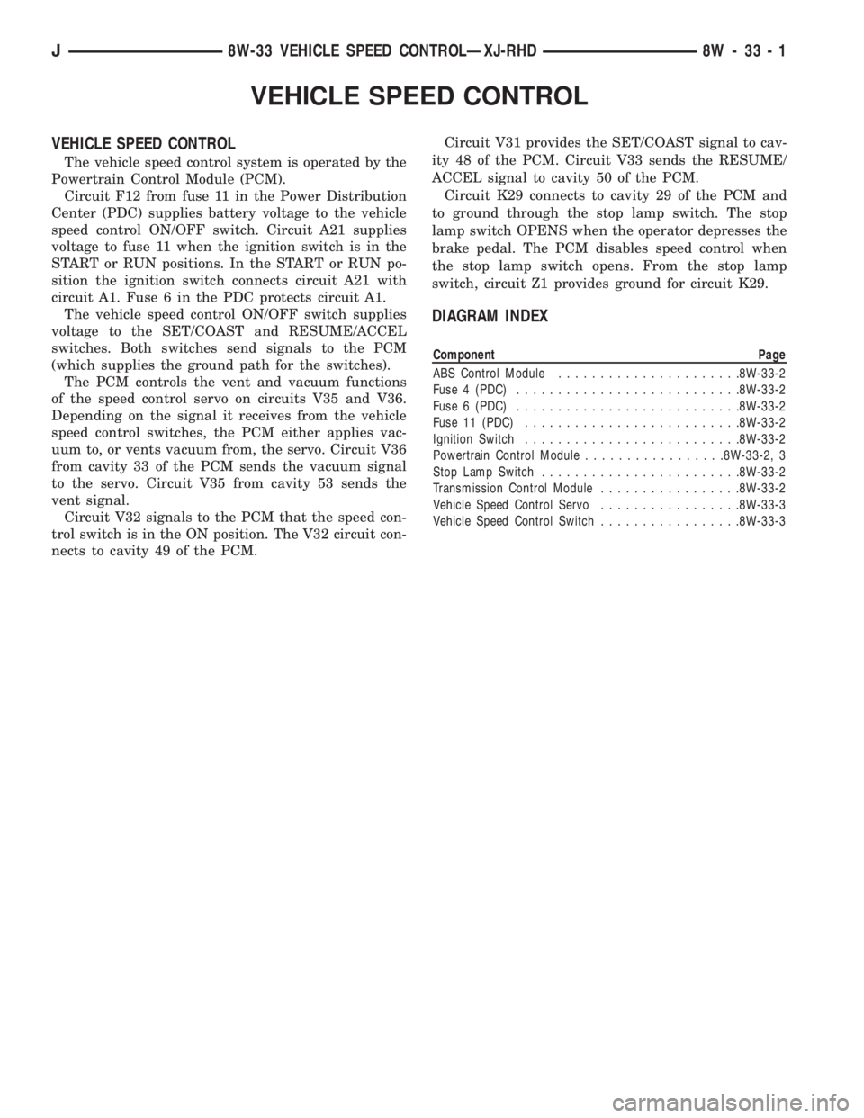
VEHICLE SPEED CONTROL
VEHICLE SPEED CONTROL
The vehicle speed control system is operated by the
Powertrain Control Module (PCM).
Circuit F12 from fuse 11 in the Power Distribution
Center (PDC) supplies battery voltage to the vehicle
speed control ON/OFF switch. Circuit A21 supplies
voltage to fuse 11 when the ignition switch is in the
START or RUN positions. In the START or RUN po-
sition the ignition switch connects circuit A21 with
circuit A1. Fuse 6 in the PDC protects circuit A1.
The vehicle speed control ON/OFF switch supplies
voltage to the SET/COAST and RESUME/ACCEL
switches. Both switches send signals to the PCM
(which supplies the ground path for the switches).
The PCM controls the vent and vacuum functions
of the speed control servo on circuits V35 and V36.
Depending on the signal it receives from the vehicle
speed control switches, the PCM either applies vac-
uum to, or vents vacuum from, the servo. Circuit V36
from cavity 33 of the PCM sends the vacuum signal
to the servo. Circuit V35 from cavity 53 sends the
vent signal.
Circuit V32 signals to the PCM that the speed con-
trol switch is in the ON position. The V32 circuit con-
nects to cavity 49 of the PCM.Circuit V31 provides the SET/COAST signal to cav-
ity 48 of the PCM. Circuit V33 sends the RESUME/
ACCEL signal to cavity 50 of the PCM.
Circuit K29 connects to cavity 29 of the PCM and
to ground through the stop lamp switch. The stop
lamp switch OPENS when the operator depresses the
brake pedal. The PCM disables speed control when
the stop lamp switch opens. From the stop lamp
switch, circuit Z1 provides ground for circuit K29.
DIAGRAM INDEX
Component Page
ABS Control Module......................8W-33-2
Fuse 4 (PDC)...........................8W-33-2
Fuse 6 (PDC)...........................8W-33-2
Fuse 11 (PDC)..........................8W-33-2
Ignition Switch..........................8W-33-2
Powertrain Control Module.................8W-33-2, 3
Stop Lamp Switch........................8W-33-2
Transmission Control Module.................8W-33-2
Vehicle Speed Control Servo.................8W-33-3
Vehicle Speed Control Switch.................8W-33-3
J8W-33 VEHICLE SPEED CONTROLÐXJ-RHD 8W - 33 - 1
Page 913 of 2158

INTERIOR LIGHTING
INDEX
page page
Cargo Lamp and Dome Lamp................. 1
Chime/Buzzer Module....................... 2
Diagram Index............................ 2
General Information........................ 1
Glove Box Lamp........................... 1Ignition Switch Lamp........................ 1
Instrument Panel Illumination Lamps............ 1
Reading Lamps........................... 1
Underhood Lamp.......................... 1
Visor Vanity Mirror Lamps.................... 1
GENERAL INFORMATION
Circuit M1 supplies power to the glove box lamp,
dome lamp, reading lamps, cargo lamp and vanity
lamps. Circuit M1 is protected by fuse 16 in the
Power Distribution Center (PDC).
Circuit E2 supplies power for the instrument panel
illumination lamps.
INSTRUMENT PANEL ILLUMINATION LAMPS
Circuit E2 from the headlamp switch splices to
supply power to the following illumination lamps:
²Ash receiver lamp
²Cigar lighter lamp
²Transmission range indicator lamp
²Transfer case range indicator lamp
²A/C-Heater switch lamp
²Heated rear window switch lamp
²Rear wiper switch lamp
²Fog lamp switch lamp
Fuse 25 in the fuse block protects circuit E2. Cir-
cuit Z1 provides ground for all of the illumination
lamps except for the cigar lighter lamp. The cigar
lighter lamp is case grounded.
HELPFUL INFORMATION
Circuit E2 also supplies power to the radio, LCD
relay and the illumination lamps in the instrument
cluster.
IGNITION SWITCH LAMP
Circuit M50 supplies voltage to the ignition switch
lamp. Circuit Z1 provides ground for the lamp.
GLOVE BOX LAMP
Circuit M1 from fuse 16 in the Power Distribution
Center (PDC) powers the glove box lamp. A case
grounded switch, in series after the lamp, closes
when the glove box door is opened. The switch com-
pletes a path to ground on circuit Z1.
CARGO LAMP AND DOME LAMP
Circuit M1 from fuse 16 in the Power Distribution
Center (PDC) supplies power to the cargo lamp anddome lamp. The M1 circuit is HOT at all times. The
ground path for the lamp is provided in three differ-
ent ways.
One way is through the door jamb switches. Circuit
M2 connects to the door jamb switches to the dome
lamp and cargo lamp. The switches are connected to
ground circuit Z1. When a door is opened, the
plunger in the switch closes, completing a path to
ground.
The second way is through the liftgate switch. Cir-
cuit G71 connects to circuit M2 at the cargo lamp
connector. Circuit G71 connects to the liftgate switch.
The liftgate switch connects to ground circuit Z1.
When the lift gate opens, the plunger in the switch
closes, completing a path to ground.
The third ground path is through the headlamp
switch. Circuit M2 is spliced in with the headlamp
switch. When the operator turns the headlamp
switch to the dome lamp ON position, a ground path
is provided through the switch.
READING LAMPS
Circuit M1 from fuse 16 in the Power Distribution
Center (PDC) supplies power to the reading lamps.
Circuit M1 is HOT at all times. When the operator
depresses the reading lamp, the reading lamp switch
closes and supplies ground on circuit Z1.
VISOR VANITY MIRROR LAMPS
Circuit M1 from fuse 16 in the Power Distribution
Center (PDC) supplies power to the vanity lamps.
Circuit M1 is HOT at all times. When the vanity
lamps switch closes, voltage flows to vanity mirror
lamps. The vanity mirror is case grounded.
UNDERHOOD LAMP
Circuit A7 from fuse 16 in the Power Distribution
Center (PDC) supplies battery voltage for the under-
hood lamp. A mercury switch, in series after the
lamp, connects the lamp to ground on circuit Z1.
When the hood is raised, mercury inside the switch
moves to a position where it connects circuit M1 to
ground circuit Z1, illuminating the lamp.
J8W-44 INTERIOR LIGHTINGÐXJ-RHD 8W - 44 - 1
Page 949 of 2158
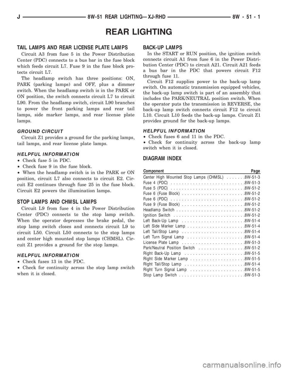
REAR LIGHTING
TAIL LAMPS AND REAR LICENSE PLATE LAMPS
Circuit A3 from fuse 5 in the Power Distribution
Center (PDC) connects to a bus bar in the fuse block
which feeds circuit L7. Fuse 9 in the fuse block pro-
tects circuit L7.
The headlamp switch has three positions: ON,
PARK (parking lamps) and OFF, plus a dimmer
switch. When the headlamp switch is in the PARK or
ON position, the switch connects circuit L7 to circuit
L90. From the headlamp switch, circuit L90 branches
to power the front parking lamps and rear tail
lamps, side marker lamps, and rear license plate
lamps.
GROUND CIRCUIT
Circuit Z1 provides a ground for the parking lamps,
tail lamps, and rear license plate lamps.
HELPFUL INFORMATION
²Check fuse 5 in PDC.
²Check fuse 9 in the fuse block.
²When the headlamp switch is in the PARK or ON
position, circuit L7 also connects to circuit E2. Cir-
cuit E2 continues through fuse 25 in the fuse block.
Circuit E2 powers the illumination lamps.
STOP LAMPS AND CHMSL LAMPS
Circuit L9 from fuse 4 in the Power Distribution
Center (PDC) connects to the stop lamp switch.
When the operator depresses the brake pedal, the
stop lamp switch closes and connects circuit L9 to
circuit L50. Circuit L50 connects to the stop lamps
and center high mounted stop lamps (CHMSL). Cir-
cuit Z1 provides a ground for the stop lamps.
HELPFUL INFORMATION
²Check fuses 13 in the PDC.
²Check for continuity across the stop lamp switch
when it is closed.
BACK-UP LAMPS
In the START or RUN position, the ignition switch
connects circuit A1 from fuse 6 in the Power Distri-
bution Center (PDC) to circuit A21. Circuit A21 feeds
a bus bar in the PDC that powers circuit F12
through fuse 11.
Circuit F12 supplies power to the back-up lamp
switch. On automatic transmission equipped vehicles,
the back-up lamp switch is part of an assembly that
includes the PARK/NEUTRAL position switch. When
the operator puts the transmission in REVERSE, the
back-up lamp switch connects circuit F12 to circuit
L10. Circuit L10 feeds the back-up lamps. Circuit Z1
provides ground for the back-up lamps.
HELPFUL INFORMATION
²Check fuses 6 and 11 in the PDC.
²Check for continuity across the back-up lamp
switch when it is closed.
DIAGRAM INDEX
Component Page
Center High Mounted Stop Lamps (CHMSL).......8W-51-3
Fuse 4 (PDC)...........................8W-51-3
Fuse 5 (PDC)...........................8W-51-2
Fuse 6 (Fuse Block).......................8W-51-2
Fuse 6 (PDC)...........................8W-51-2
Fuse 9 (Fuse Block).......................8W-51-2
Headlamp Switch.........................8W-51-2
Ignition Switch..........................8W-51-2
Left Back-Up Lamp.......................8W-51-4
Left Side Marker Lamp.....................8W-51-4
Left Tail/Stop Lamp.......................8W-51-4
Left Turn Signal Lamp.....................8W-51-4
License Plate Lamp.......................8W-51-3
Park/Neutral Position Switch.................8W-51-2
Right Back-Up Lamp......................8W-51-5
Right Side Marker Lamp....................8W-51-5
Right Tail/Stop Lamp......................8W-51-4
Right Turn Signal Lamp....................8W-51-5
Stop Lamp Switch........................8W-51-3
J8W-51 REAR LIGHTINGÐXJ-RHD 8W - 51 - 1
Page 955 of 2158
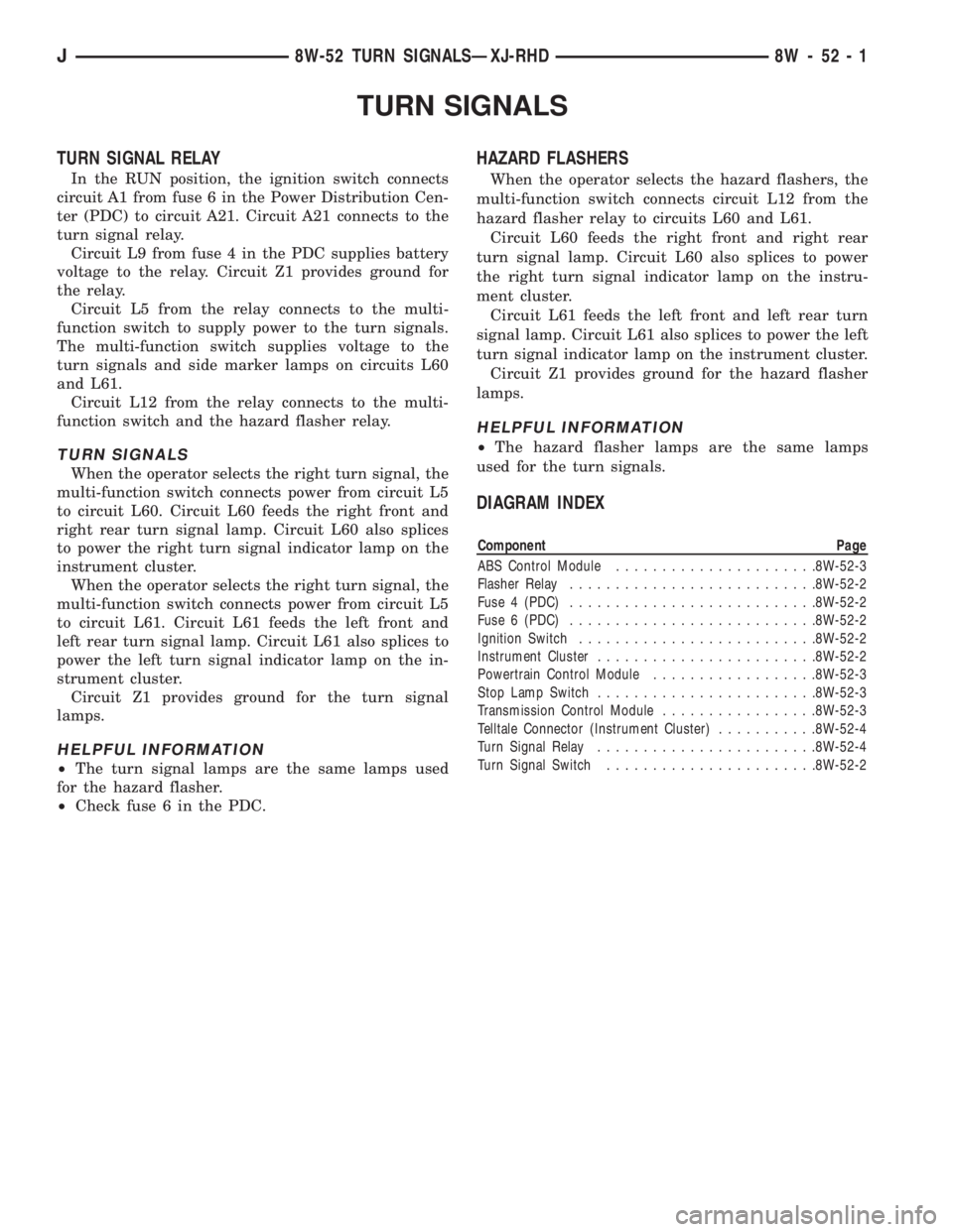
TURN SIGNALS
TURN SIGNAL RELAY
In the RUN position, the ignition switch connects
circuit A1 from fuse 6 in the Power Distribution Cen-
ter (PDC) to circuit A21. Circuit A21 connects to the
turn signal relay.
Circuit L9 from fuse 4 in the PDC supplies battery
voltage to the relay. Circuit Z1 provides ground for
the relay.
Circuit L5 from the relay connects to the multi-
function switch to supply power to the turn signals.
The multi-function switch supplies voltage to the
turn signals and side marker lamps on circuits L60
and L61.
Circuit L12 from the relay connects to the multi-
function switch and the hazard flasher relay.
TURN SIGNALS
When the operator selects the right turn signal, the
multi-function switch connects power from circuit L5
to circuit L60. Circuit L60 feeds the right front and
right rear turn signal lamp. Circuit L60 also splices
to power the right turn signal indicator lamp on the
instrument cluster.
When the operator selects the right turn signal, the
multi-function switch connects power from circuit L5
to circuit L61. Circuit L61 feeds the left front and
left rear turn signal lamp. Circuit L61 also splices to
power the left turn signal indicator lamp on the in-
strument cluster.
Circuit Z1 provides ground for the turn signal
lamps.
HELPFUL INFORMATION
²The turn signal lamps are the same lamps used
for the hazard flasher.
²Check fuse 6 in the PDC.
HAZARD FLASHERS
When the operator selects the hazard flashers, the
multi-function switch connects circuit L12 from the
hazard flasher relay to circuits L60 and L61.
Circuit L60 feeds the right front and right rear
turn signal lamp. Circuit L60 also splices to power
the right turn signal indicator lamp on the instru-
ment cluster.
Circuit L61 feeds the left front and left rear turn
signal lamp. Circuit L61 also splices to power the left
turn signal indicator lamp on the instrument cluster.
Circuit Z1 provides ground for the hazard flasher
lamps.
HELPFUL INFORMATION
²The hazard flasher lamps are the same lamps
used for the turn signals.
DIAGRAM INDEX
Component Page
ABS Control Module......................8W-52-3
Flasher Relay...........................8W-52-2
Fuse 4 (PDC)...........................8W-52-2
Fuse 6 (PDC)...........................8W-52-2
Ignition Switch..........................8W-52-2
Instrument Cluster........................8W-52-2
Powertrain Control Module..................8W-52-3
Stop Lamp Switch........................8W-52-3
Transmission Control Module.................8W-52-3
Telltale Connector (Instrument Cluster)...........8W-52-4
Turn Signal Relay........................8W-52-4
Turn Signal Switch.......................8W-52-2
J8W-52 TURN SIGNALSÐXJ-RHD 8W - 52 - 1
Page 1068 of 2158
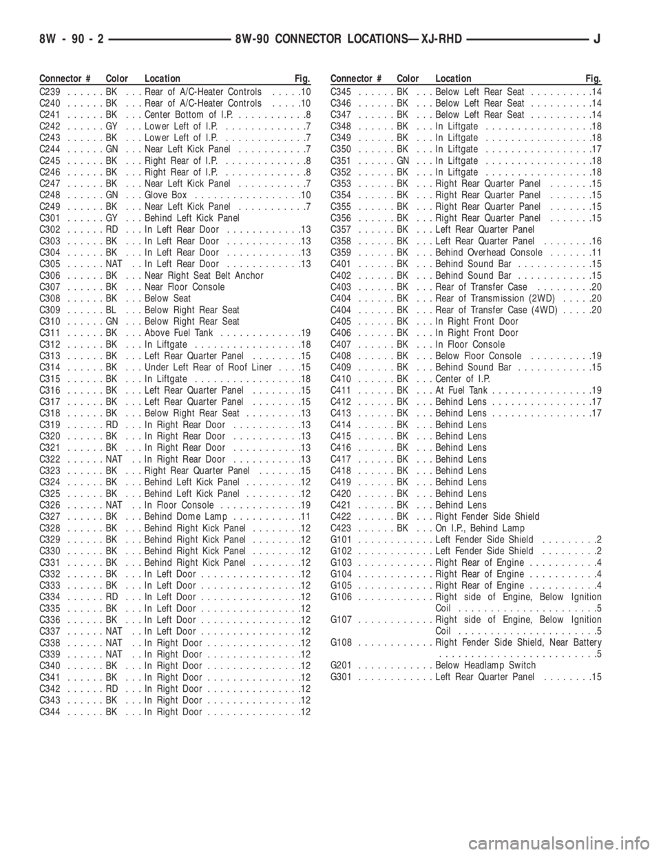
Connector # Color Location Fig.
C239......BK ...Rear of A/C-Heater Controls.....10
C240......BK ...Rear of A/C-Heater Controls.....10
C241......BK ...Center Bottom of I.P............8
C242......GY ...Lower Left of I.P..............7
C243......BK ...Lower Left of I.P..............7
C244......GN ...Near Left Kick Panel...........7
C245......BK ...Right Rear of I.P..............8
C246......BK ...Right Rear of I.P..............8
C247......BK ...Near Left Kick Panel...........7
C248......GN ...Glove Box.................10
C249......BK ...Near Left Kick Panel...........7
C301......GY ...Behind Left Kick Panel
C302......RD ...InLeft Rear Door............13
C303......BK ...InLeft Rear Door............13
C304......BK ...InLeft Rear Door............13
C305......NAT ..InLeft Rear Door............13
C306......BK ...Near Right Seat Belt Anchor
C307......BK ...Near Floor Console
C308......BK ...Below Seat
C309......BL ...Below Right Rear Seat
C310......GN ...Below Right Rear Seat
C311......BK ...Above Fuel Tank.............19
C312......BK ...InLiftgate.................18
C313......BK ...Left Rear Quarter Panel........15
C314......BK ...Under Left Rear of Roof Liner....15
C315......BK ...InLiftgate.................18
C316......BK ...Left Rear Quarter Panel........15
C317......BK ...Left Rear Quarter Panel........15
C318......BK ...Below Right Rear Seat.........13
C319......RD ...InRight Rear Door...........13
C320......BK ...InRight Rear Door...........13
C321......BK ...InRight Rear Door...........13
C322......NAT ..InRight Rear Door...........13
C323......BK ...Right Rear Quarter Panel.......15
C324......BK ...Behind Left Kick Panel.........12
C325......BK ...Behind Left Kick Panel.........12
C326......NAT ..InFloor Console.............19
C327......BK ...Behind Dome Lamp...........11
C328......BK ...Behind Right Kick Panel........12
C329......BK ...Behind Right Kick Panel........12
C330......BK ...Behind Right Kick Panel........12
C331......BK ...Behind Right Kick Panel........12
C332......BK ...InLeft Door................12
C333......BK ...InLeft Door................12
C334......RD ...InLeft Door................12
C335......BK ...InLeft Door................12
C336......BK ...InLeft Door................12
C337......NAT ..InLeft Door................12
C338......NAT ..InRight Door...............12
C339......NAT ..InRight Door...............12
C340......BK ...InRight Door...............12
C341......BK ...InRight Door...............12
C342......RD ...InRight Door...............12
C343......BK ...InRight Door...............12
C344......BK ...InRight Door...............12Connector # Color Location Fig.
C345......BK ...Below Left Rear Seat..........14
C346......BK ...Below Left Rear Seat..........14
C347......BK ...Below Left Rear Seat..........14
C348......BK ...InLiftgate.................18
C349......BK ...InLiftgate.................18
C350......BK ...InLiftgate.................17
C351......GN ...InLiftgate.................18
C352......BK ...InLiftgate.................18
C353......BK ...Right Rear Quarter Panel.......15
C354......BK ...Right Rear Quarter Panel.......15
C355......BK ...Right Rear Quarter Panel.......15
C356......BK ...Right Rear Quarter Panel.......15
C357......BK ...Left Rear Quarter Panel
C358......BK ...Left Rear Quarter Panel........16
C359......BK ...Behind Overhead Console.......11
C401......BK ...Behind Sound Bar............15
C402......BK ...Behind Sound Bar............15
C403......BK ...Rear of Transfer Case.........20
C404......BK ...Rear of Transmission (2WD).....20
C404......BK ...Rear of Transfer Case (4WD).....20
C405......BK ...InRight Front Door
C406......BK ...InRight Front Door
C407......BK ...InFloor Console
C408......BK ...Below Floor Console..........19
C409......BK ...Behind Sound Bar............15
C410......BK ...Center of I.P.
C411......BK ...AtFuel Tank................19
C412......BK ...Behind Lens................17
C413......BK ...Behind Lens................17
C414......BK ...Behind Lens
C415......BK ...Behind Lens
C416......BK ...Behind Lens
C417......BK ...Behind Lens
C418......BK ...Behind Lens
C419......BK ...Behind Lens
C420......BK ...Behind Lens
C421......BK ...Behind Lens
C422......BK ...Right Fender Side Shield
C423......BK ...OnI.P.,Behind Lamp
G101............Left Fender Side Shield.........2
G102............Left Fender Side Shield.........2
G103............Right Rear of Engine...........4
G104............Right Rear of Engine...........4
G105............Right Rear of Engine...........4
G106............Right side of Engine, Below Ignition
Coil......................5
G107............Right side of Engine, Below Ignition
Coil......................5
G108............Right Fender Side Shield, Near Battery
.........................5
G201............Below Headlamp Switch
G301............Left Rear Quarter Panel........15
8W - 90 - 2 8W-90 CONNECTOR LOCATIONSÐXJ-RHDJ
Page 1084 of 2158
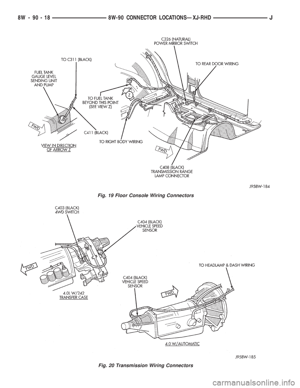
Fig. 19 Floor Console Wiring Connectors
Fig. 20 Transmission Wiring Connectors
8W - 90 - 18 8W-90 CONNECTOR LOCATIONSÐXJ-RHDJ