1995 JEEP XJ washer fluid
[x] Cancel search: washer fluidPage 1816 of 2158
use shop towels or rags. Lint or foreign material from
towels or rags can interfere with valve operation.
(13) Inspect condition of lower body components.
Replace lower body if any bores are scored or cor-
roded. Replace valves, plugs or sleeves that are
scored or worn. Replace oil strainers if cut, torn or
damaged in any way.
(14) Inspect valve body springs. Replace any spring
having rusted, distorted, or collapsed coils. Measure
length of each valve body spring. Replace any spring
if free length is less than length specified in following
chart (Fig. 11).
LOWER BODY ASSEMBLY
(1) Lubricate lower body components with auto-
matic transmission fluid.
(2) Install spring and accumulator control valve in
sleeve (Fig. 11). Then install assembled components
in lower body (Fig. 9).(3) Press accumulator control valve assembly into
valve bore and install retainer (Fig. 9).
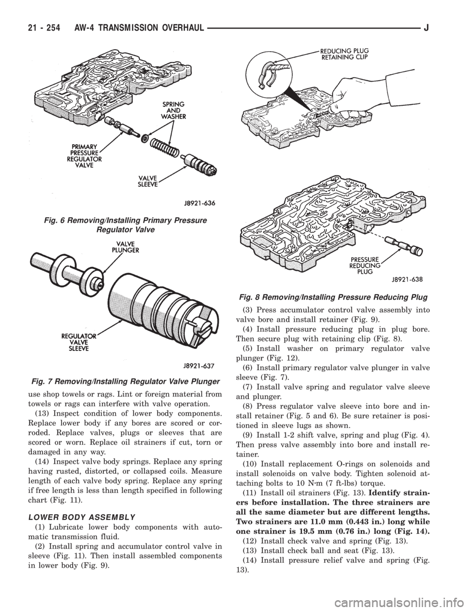
(4) Install pressure reducing plug in plug bore.
Then secure plug with retaining clip (Fig. 8).
(5) Install washer on primary regulator valve
plunger (Fig. 12).
(6) Install primary regulator valve plunger in valve
sleeve (Fig. 7).
(7) Install valve spring and regulator valve sleeve
and plunger.
(8) Press regulator valve sleeve into bore and in-
stall retainer (Fig. 5 and 6). Be sure retainer is posi-
tioned in sleeve lugs as shown.
(9) Install 1-2 shift valve, spring and plug (Fig. 4).
Then press valve assembly into bore and install re-
tainer.
(10) Install replacement O-rings on solenoids and
install solenoids on valve body. Tighten solenoid at-
taching bolts to 10 Nzm (7 ft-lbs) torque.
(11) Install oil strainers (Fig. 13).Identify strain-
ers before installation. The three strainers are
all the same diameter but are different lengths.
Two strainers are 11.0 mm (0.443 in.) long while
one strainer is 19.5 mm (0.76 in.) long (Fig. 14).
(12) Install check valve and spring (Fig. 13).
(13) Install check ball and seat (Fig. 13).
(14) Install pressure relief valve and spring (Fig.
13).
Fig. 6 Removing/Installing Primary Pressure
Regulator Valve
Fig. 7 Removing/Installing Regulator Valve Plunger
Fig. 8 Removing/Installing Pressure Reducing Plug
21 - 254 AW-4 TRANSMISSION OVERHAULJ
Page 1862 of 2158
MAINSHAFT ASSEMBLY
(1) If drive sprocket bearings are to be replaced,
remove and install them as follows:
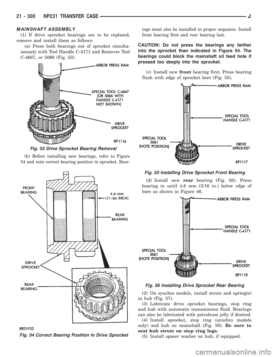
(a) Press both bearings out of sprocket simulta-
neously with Tool Handle C-4171 and Remover Tool
C-4667, or 5066 (Fig. 53).
(b) Before installing new bearings, refer to Figure
54 and note correct bearing position in sprocket. Bear-ings must also be installed in proper sequence. Install
front bearing first and rear bearing last.
CAUTION: Do not press the bearings any farther
into the sprocket than indicated in Figure 54. The
bearings could block the mainshaft oil feed hole if
pressed too deeply into the sprocket.
(c) Install newfrontbearing first. Press bearing
flush with edge of sprocket bore (Fig. 55).
(d) Install newrearbearing (Fig. 56). Press
bearing in until 4.6 mm (3/16 in.) below edge of
bore as shown in Figure 46.
(2) On synchro models, install struts and spring(s)
in hub (Fig. 57).
(3) Lubricate drive sprocket bearings, stop ring
and hub with automatic transmission fluid. Bearings
can also be lubricated with petroleum jelly if desired.
(4) Install sprocket, stop ring (synchro models
only) and hub on mainshaft (Fig. 58).Be sure to
seat hub struts on stop ring lugs.
(5) Install spacer washer on hub, if equipped.
Fig. 54 Correct Bearing Position In Drive Sprocket
Fig. 53 Drive Sprocket Bearing Removal
Fig. 55 Installing Drive Sprocket Front Bearing
Fig. 56 Installing Drive Sprocket Rear Bearing
21 - 300 NP231 TRANSFER CASEJ
Page 1881 of 2158
Inspect the differential gears, thrust washers and
case halves. Replace the mainshaft gear if the gear
teeth or the brass ring on the underside of the gear
are damaged. Replace the differential as an assembly
if the gears, case halves, or the pins in the lower case
half are damaged.
Inspect the case halves, extension housing and re-
tainers for cracks, porosity, or damaged sealing sur-
faces. Inspect the shafts, gears, chain and shift
components for wear or damage.
Inspect all of the transfer case bearings for wear,
roughness, pitting, or galling. Replace worn or dam-
aged bearings as outlined in the assembly section.
TRANSFER CASE ASSEMBLY
(1) Lubricate transfer case components with auto-
matic transmission fluid or petroleum jelly (where in-
dicated) during assembly.
CAUTION: The bearing bores in various transfer
case components contain oil feed holes. Be sure re-
placement bearings do not block these feed holes.
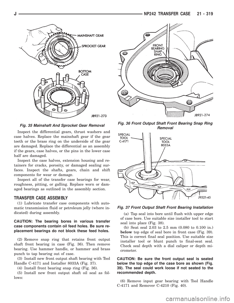
(2) Remove snap ring that retains front output
shaft front bearing in case (Fig. 36). Then remove
bearing. Use hammer handle, or hammer and brass
punch to tap bearing out of case.
(3) Install new front output shaft bearing with Tool
Handle C-4171 and Installer 8033A (Fig. 37).
(4) Install front bearing snap ring (Fig. 36).
(5) Install new front output shaft oil seal as fol-
lows:(a) Tap seal into bore until flush with upper edge
of case bore. Use suitable size installer tool to start
seal into place (Fig. 38).
(b) Seat seal 2.03 to 2.5 mm (0.080 to 0.100 in.)
belowtop edge of seal bore in front case (Fig. 39).
This is correct final seal position. Use suitable size
installer tool or blunt punch to final-seat seal.
Check seal depth with a dial caliper or depth mi-
crometer.
CAUTION: Be sure the front output seal is seated
below the top edge of the case bore as shown (Fig.
39). The seal could work loose if not seated to the
recommended depth.
(6) Remove input gear bearing with Tool Handle
C-4171 and Remover C-4210 (Fig. 40).
Fig. 35 Mainshaft And Sprocket Gear RemovalFig. 36 Front Output Shaft Front Bearing Snap Ring
Removal
Fig. 37 Front Output Shaft Front Bearing Installation
JNP242 TRANSFER CASE 21 - 319
Page 1883 of 2158
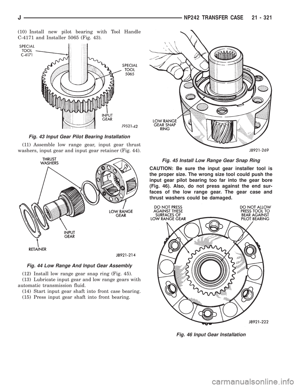
(10) Install new pilot bearing with Tool Handle
C-4171 and Installer 5065 (Fig. 43).
(11) Assemble low range gear, input gear thrust
washers, input gear and input gear retainer (Fig. 44).
(12) Install low range gear snap ring (Fig. 45).
(13) Lubricate input gear and low range gears with
automatic transmission fluid.
(14) Start input gear shaft into front case bearing.
(15) Press input gear shaft into front bearing.CAUTION: Be sure the input gear installer tool is
the proper size. The wrong size tool could push the
input gear pilot bearing too far into the gear bore
(Fig. 46). Also, do not press against the end sur-
faces of the low range gear. The gear case and
thrust washers could be damaged.
Fig. 43 Input Gear Pilot Bearing Installation
Fig. 44 Low Range And Input Gear Assembly
Fig. 45 Install Low Range Gear Snap Ring
Fig. 46 Input Gear Installation
JNP242 TRANSFER CASE 21 - 321
Page 1885 of 2158
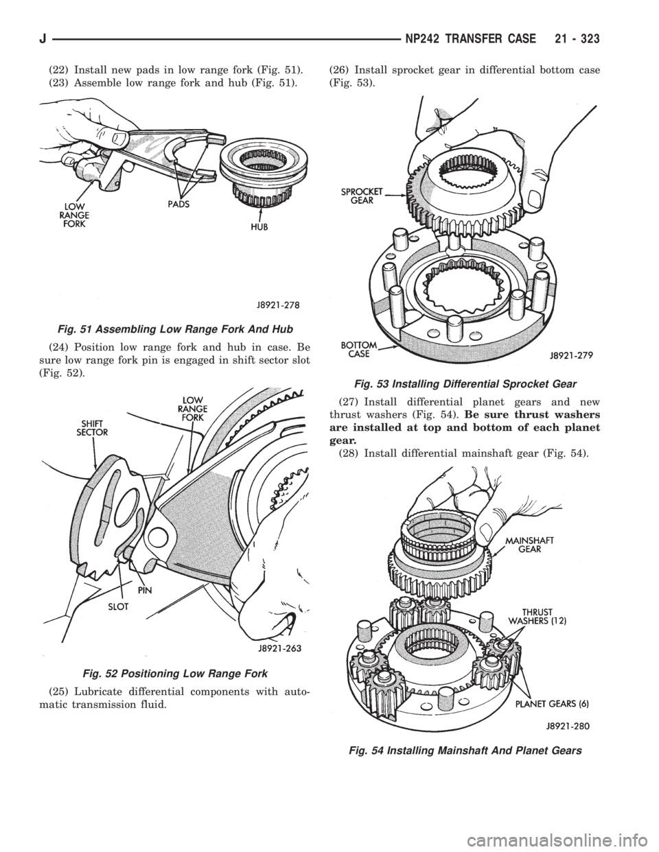
(22) Install new pads in low range fork (Fig. 51).
(23) Assemble low range fork and hub (Fig. 51).
(24) Position low range fork and hub in case. Be
sure low range fork pin is engaged in shift sector slot
(Fig. 52).
(25) Lubricate differential components with auto-
matic transmission fluid.(26) Install sprocket gear in differential bottom case
(Fig. 53).
(27) Install differential planet gears and new
thrust washers (Fig. 54).Be sure thrust washers
are installed at top and bottom of each planet
gear.
(28) Install differential mainshaft gear (Fig. 54).
Fig. 51 Assembling Low Range Fork And Hub
Fig. 52 Positioning Low Range Fork
Fig. 53 Installing Differential Sprocket Gear
Fig. 54 Installing Mainshaft And Planet Gears
JNP242 TRANSFER CASE 21 - 323
Page 1931 of 2158
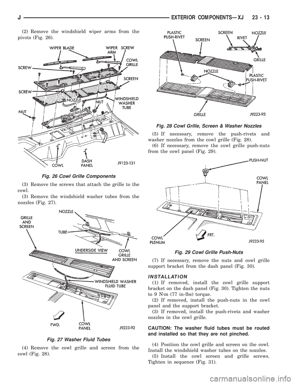
(2) Remove the windshield wiper arms from the
pivots (Fig. 26).
(3) Remove the screws that attach the grille to the
cowl.
(3) Remove the windshield washer tubes from the
nozzles (Fig. 27).
(4) Remove the cowl grille and screen from the
cowl (Fig. 28).(5) If necessary, remove the push-rivets and
washer nozzles from the cowl grille (Fig. 28).
(6) If necessary, remove the cowl grille push-nuts
from the cowl panel (Fig. 29).
(7) If necessary, remove the nuts and cowl grille
support bracket from the dash panel (Fig. 30).
INSTALLATION
(1) If removed, install the cowl grille support
bracket on the dash panel (Fig. 30). Tighten the nuts
to9Nzm (77 in-lbs) torque.
(2) If removed, install the push-nuts in the cowl
panel and the support bracket.
(3) If removed, install the push-rivets and washer
nozzles in the cowl grille.
CAUTION: The washer fluid tubes must be routed
and installed so that they are not pinched.
(4) Position the cowl grille and screen on the cowl.
Install the windshield washer tubes on the nozzles.
(5) Install the cowl screen and grille screws.
Tighten in sequence (Fig. 31).
Fig. 26 Cowl Grille Components
Fig. 27 Washer Fluid Tubes
Fig. 28 Cowl Grille, Screen & Washer Nozzles
Fig. 29 Cowl Grille Push-Nuts
JEXTERIOR COMPONENTSÐXJ 23 - 13
Page 1934 of 2158
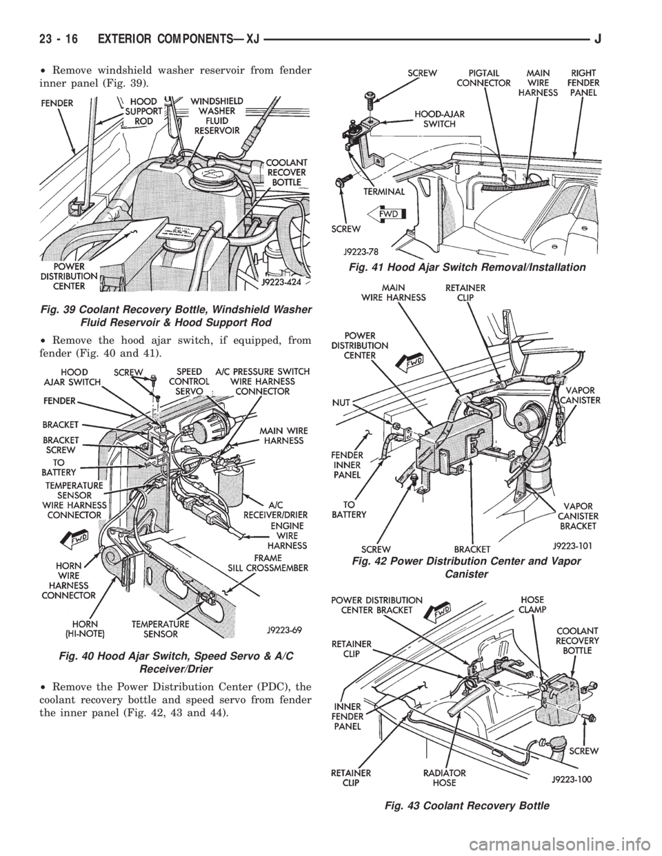
²Remove windshield washer reservoir from fender
inner panel (Fig. 39).
²Remove the hood ajar switch, if equipped, from
fender (Fig. 40 and 41).
²Remove the Power Distribution Center (PDC), the
coolant recovery bottle and speed servo from fender
the inner panel (Fig. 42, 43 and 44).
Fig. 41 Hood Ajar Switch Removal/Installation
Fig. 42 Power Distribution Center and Vapor
Canister
Fig. 43 Coolant Recovery Bottle
Fig. 39 Coolant Recovery Bottle, Windshield Washer
Fluid Reservoir & Hood Support Rod
Fig. 40 Hood Ajar Switch, Speed Servo & A/C
Receiver/Drier
23 - 16 EXTERIOR COMPONENTSÐXJJ
Page 1937 of 2158
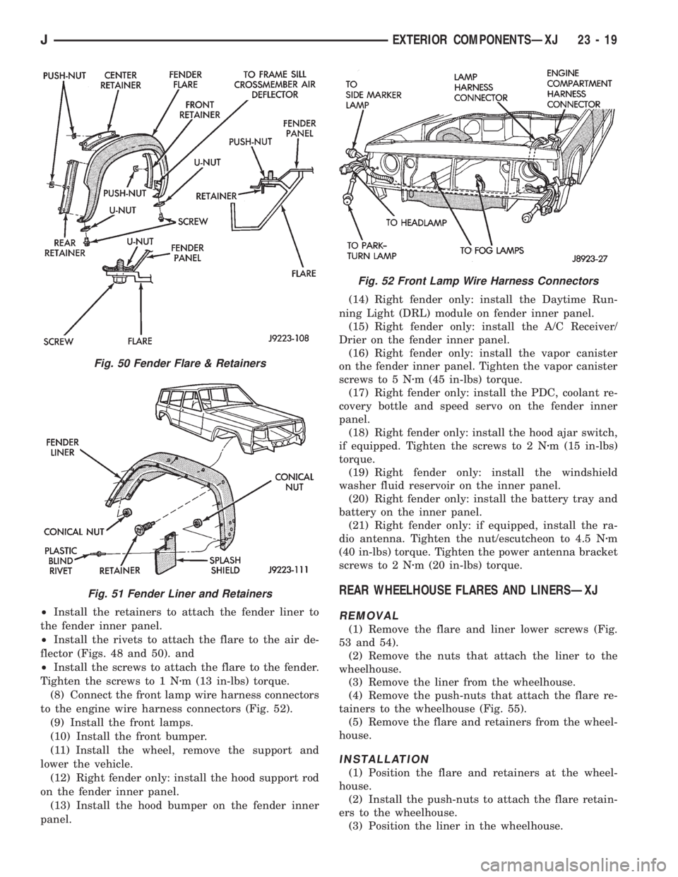
²Install the retainers to attach the fender liner to
the fender inner panel.
²Install the rivets to attach the flare to the air de-
flector (Figs. 48 and 50). and
²Install the screws to attach the flare to the fender.
Tighten the screws to 1 Nzm (13 in-lbs) torque.
(8) Connect the front lamp wire harness connectors
to the engine wire harness connectors (Fig. 52).
(9) Install the front lamps.
(10) Install the front bumper.
(11) Install the wheel, remove the support and
lower the vehicle.
(12) Right fender only: install the hood support rod
on the fender inner panel.
(13) Install the hood bumper on the fender inner
panel.(14) Right fender only: install the Daytime Run-
ning Light (DRL) module on fender inner panel.
(15) Right fender only: install the A/C Receiver/
Drier on the fender inner panel.
(16) Right fender only: install the vapor canister
on the fender inner panel. Tighten the vapor canister
screws to 5 Nzm (45 in-lbs) torque.
(17) Right fender only: install the PDC, coolant re-
covery bottle and speed servo on the fender inner
panel.
(18) Right fender only: install the hood ajar switch,
if equipped. Tighten the screws to 2 Nzm (15 in-lbs)
torque.
(19) Right fender only: install the windshield
washer fluid reservoir on the inner panel.
(20) Right fender only: install the battery tray and
battery on the inner panel.
(21) Right fender only: if equipped, install the ra-
dio antenna. Tighten the nut/escutcheon to 4.5 Nzm
(40 in-lbs) torque. Tighten the power antenna bracket
screws to 2 Nzm (20 in-lbs) torque.
REAR WHEELHOUSE FLARES AND LINERSÐXJ
REMOVAL
(1) Remove the flare and liner lower screws (Fig.
53 and 54).
(2) Remove the nuts that attach the liner to the
wheelhouse.
(3) Remove the liner from the wheelhouse.
(4) Remove the push-nuts that attach the flare re-
tainers to the wheelhouse (Fig. 55).
(5) Remove the flare and retainers from the wheel-
house.
INSTALLATION
(1) Position the flare and retainers at the wheel-
house.
(2) Install the push-nuts to attach the flare retain-
ers to the wheelhouse.
(3) Position the liner in the wheelhouse.
Fig. 50 Fender Flare & Retainers
Fig. 51 Fender Liner and Retainers
Fig. 52 Front Lamp Wire Harness Connectors
JEXTERIOR COMPONENTSÐXJ 23 - 19