1995 JEEP XJ washer fluid
[x] Cancel search: washer fluidPage 1507 of 2158
PITMAN SHAFT SEALSÐIN CAR REPLACEMENT
REMOVAL
(1) Remove pitman arm from gear. Refer to Pitman
Arm Removal in Steering Linkage.
(2) Clean exposed end of pitman shaft and hous-
ing. Use a wire brush to clean the shaft splines.
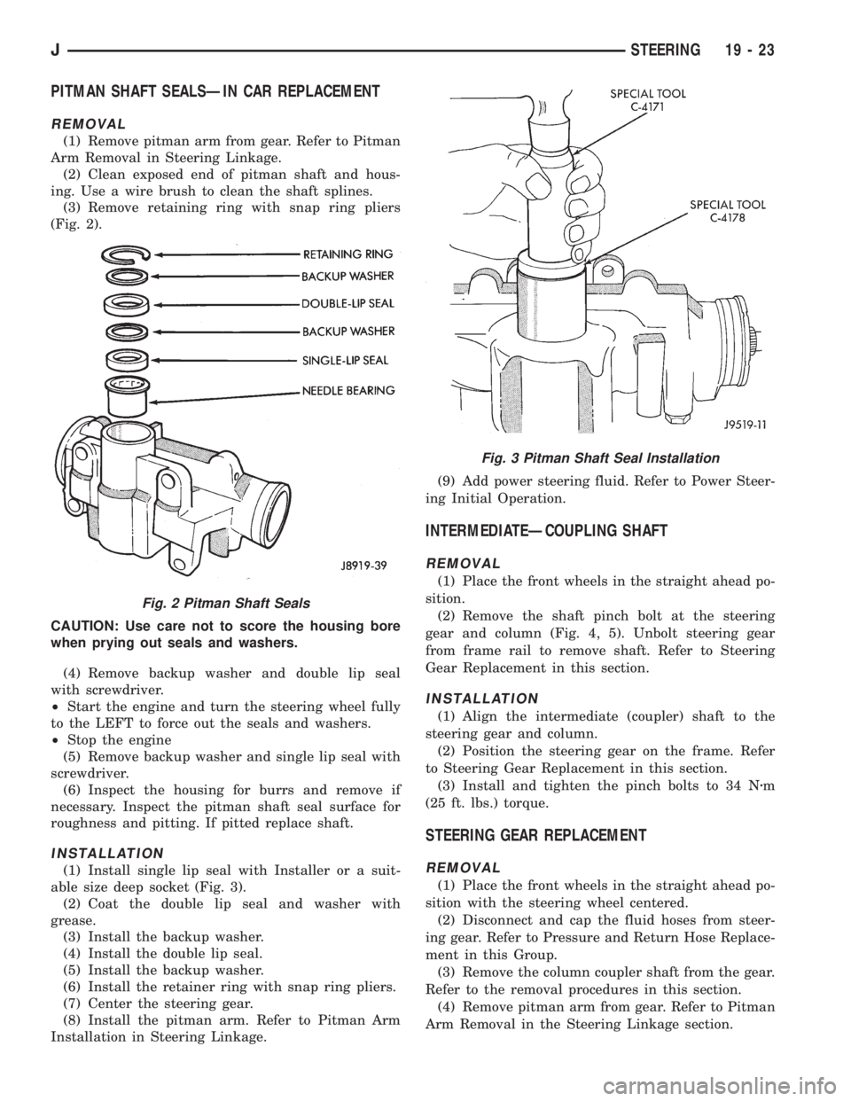
(3) Remove retaining ring with snap ring pliers
(Fig. 2).
CAUTION: Use care not to score the housing bore
when prying out seals and washers.
(4) Remove backup washer and double lip seal
with screwdriver.
²Start the engine and turn the steering wheel fully
to the LEFT to force out the seals and washers.
²Stop the engine
(5) Remove backup washer and single lip seal with
screwdriver.
(6) Inspect the housing for burrs and remove if
necessary. Inspect the pitman shaft seal surface for
roughness and pitting. If pitted replace shaft.
INSTALLATION
(1) Install single lip seal with Installer or a suit-
able size deep socket (Fig. 3).
(2) Coat the double lip seal and washer with
grease.
(3) Install the backup washer.
(4) Install the double lip seal.
(5) Install the backup washer.
(6) Install the retainer ring with snap ring pliers.
(7) Center the steering gear.
(8) Install the pitman arm. Refer to Pitman Arm
Installation in Steering Linkage.(9) Add power steering fluid. Refer to Power Steer-
ing Initial Operation.
INTERMEDIATEÐCOUPLING SHAFT
REMOVAL
(1) Place the front wheels in the straight ahead po-
sition.
(2) Remove the shaft pinch bolt at the steering
gear and column (Fig. 4, 5). Unbolt steering gear
from frame rail to remove shaft. Refer to Steering
Gear Replacement in this section.
INSTALLATION
(1) Align the intermediate (coupler) shaft to the
steering gear and column.
(2) Position the steering gear on the frame. Refer
to Steering Gear Replacement in this section.
(3) Install and tighten the pinch bolts to 34 Nzm
(25 ft. lbs.) torque.
STEERING GEAR REPLACEMENT
REMOVAL
(1) Place the front wheels in the straight ahead po-
sition with the steering wheel centered.
(2) Disconnect and cap the fluid hoses from steer-
ing gear. Refer to Pressure and Return Hose Replace-
ment in this Group.
(3) Remove the column coupler shaft from the gear.
Refer to the removal procedures in this section.
(4) Remove pitman arm from gear. Refer to Pitman
Arm Removal in the Steering Linkage section.
Fig. 2 Pitman Shaft Seals
Fig. 3 Pitman Shaft Seal Installation
JSTEERING 19 - 23
Page 1513 of 2158
CAUTION: Do not turn stub shaft any farther than
necessary. The recirculating balls will drop out of
the rack piston circuit and fall inside the rack pis-
ton chamber.
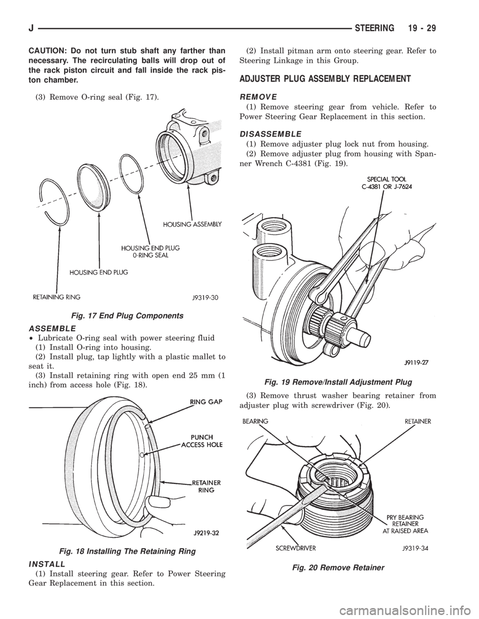
(3) Remove O-ring seal (Fig. 17).
ASSEMBLE
²Lubricate O-ring seal with power steering fluid
(1) Install O-ring into housing.
(2) Install plug, tap lightly with a plastic mallet to
seat it.
(3) Install retaining ring with open end 25 mm (1
inch) from access hole (Fig. 18).
INSTALL
(1) Install steering gear. Refer to Power Steering
Gear Replacement in this section.(2) Install pitman arm onto steering gear. Refer to
Steering Linkage in this Group.
ADJUSTER PLUG ASSEMBLY REPLACEMENT
REMOVE
(1) Remove steering gear from vehicle. Refer to
Power Steering Gear Replacement in this section.
DISASSEMBLE
(1) Remove adjuster plug lock nut from housing.
(2) Remove adjuster plug from housing with Span-
ner Wrench C-4381 (Fig. 19).
(3) Remove thrust washer bearing retainer from
adjuster plug with screwdriver (Fig. 20).
Fig. 17 End Plug Components
Fig. 18 Installing The Retaining Ring
Fig. 19 Remove/Install Adjustment Plug
Fig. 20 Remove Retainer
JSTEERING 19 - 29
Page 1666 of 2158

on transmission. Tighten pan bolts to 17 Nzm (150 in.
lbs.) torque.
(7) Lower vehicle.
(8) Refill transmission with Mopar ATF Plus.
VALVE BODY REMOVAL
(1) Raise vehicle.
(2) Remove oil pan and drain fluid.
(3) Disconnect gearshift and throttle linkage at
transmission levers.
(4) Loosen clamp bolts and remove throttle and
manual valve levers from manual valve shaft.
(5) Disconnect park/neutral position switch wires
and remove switch and switch seal.
(6) Remove valve body oil filter.
(7) Remove valve body attaching screws. Lower
valve body slightly and remove accumulator piston
and spring (Fig. 11). Rotate valve body down and
away from case. Pull it forward to disengage park
rod and remove valve body.
(8) Position valve body on bench or on repair stand
for disassembly, cleaning and inspection (Fig. 12).
VALVE BODY SERVICE
The valve body can be disassembled for cleaning
and inspection of the individual components. Valve
body service procedures are detailed in the overhaul
section.
The only serviceable valve body components are:
²park lock rod and E-clip
²switch valve and spring
²pressure adjusting screw bracket
²throttle valve lever
²manual lever
²manual lever shaft seal, washer, E-clip and detent
ball
²fluid filter
²converter clutch solenoid
The remaining valve body components are serviced
only as part of a complete valve body assembly.
VALVE BODY INSTALLATION
(1) Place valve body manual lever in low (1 posi-
tion) so park lock rod can be installed in sprag.
(2) Position park sprag with screwdriver to ease
lock rod installation and engagement.
(3) Install new seals on accumulator piston if nec-
essary and install piston in case. A small amount of
petroleum jelly can be used to hold piston in place.
(4) Lubricate shaft of manual lever and lip of shaft
seal with petroleum jelly.
(5) Raise valve body and align park rod with case
opening and park sprag. Then push rod end through
opening and past sprag. Rotate propeller shaft if nec-
essary.
(6) Position accumulator spring on transfer plate.
Fig. 10 Oil Filter Screw Locations
Fig. 11 Accumulator Piston And Spring
Fig. 12 Valve Body Assembly
21 - 104 30RH/32RH IN-VEHICLE SERVICEJ
Page 1667 of 2158
(7) Align valve body and seat it on case. Be sure
manual lever shaft and accumulator spring are prop-
erly seated.
(8) Hold valve body in position and install one or
two attaching bolts to hold valve body in place.
(9) Install remaining valve body bolts. Tighten all
bolts evenly in a diagonal pattern to 12 Nzm (105 in-
lbs) torque.
(10) Install new oil filter and tighten filter screws
to4Nzm (35 in. lbs.) torque.
(11) Connect converter solenoid wire to case con-
nector.
(12) Install manual and throttle levers on throttle
lever shaft. Tighten lever clamp screws and check for
free operation. Shaft and levers must operate freely
without any bind.
(13) Install oil pan and new gasket. Tighten pan
bolts to 17 Nzm (13 ft. lbs.) torque.
(14) Install seal on neutral switch, install switch in
case, and connect switch wires.
(15) Lower vehicle.
(16) Fill transmission with Mopar ATF Plus, Type
7176 fluid.
(17) Adjust gearshift linkage and throttle valve
(kickdown) cable if necessary.
GOVERNOR AND PARK GEAR SERVICE
GOVERNOR/PARK GEAR REMOVAL
(1) Raise vehicle.
(2) Mark both propeller shaft yokes for assembly
reference and disconnect propeller shafts at transfer
case.
(3) Disconnect speed sensor wires and remove
speedometer adapter and sensor.
(4) Position support stand under transmission con-
verter housing.
(5) Remove rear crossmember.
(6) Disconnect parking brake cable at equalizer
and disconnect exhaust components as necessary.
(7) Support transfer case with jack.
(8) Remove bolts attaching transfer case to trans-
mission adapter housing and remove transfer case.
(9) Remove bolts attaching adapter, or extension
housing to transmission and remove adapter/housing.
(10) Loosen but do not remove bolts that attach
governor body to park gear.
(11) Rotate transmission output shaft until gover-
nor weight assembly is accessible. Then remove
E-clip at this end of governor shaft.
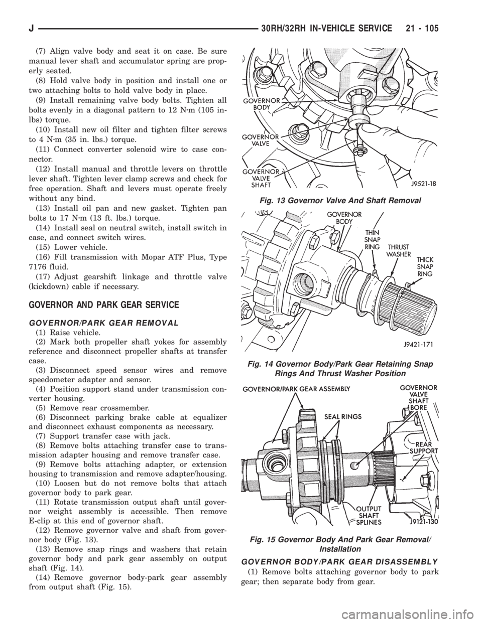
(12) Remove governor valve and shaft from gover-
nor body (Fig. 13).
(13) Remove snap rings and washers that retain
governor body and park gear assembly on output
shaft (Fig. 14).
(14) Remove governor body-park gear assembly
from output shaft (Fig. 15).
GOVERNOR BODY/PARK GEAR DISASSEMBLY
(1) Remove bolts attaching governor body to park
gear; then separate body from gear.
Fig. 13 Governor Valve And Shaft Removal
Fig. 14 Governor Body/Park Gear Retaining Snap
Rings And Thrust Washer Position
Fig. 15 Governor Body And Park Gear Removal/
Installation
J30RH/32RH IN-VEHICLE SERVICE 21 - 105
Page 1669 of 2158
Governor/Park Gear Cleaning and Inspection
Thoroughly clean all the governor parts in a suit-
able cleaning solution but do not use any type of
caustic cleaning agents.
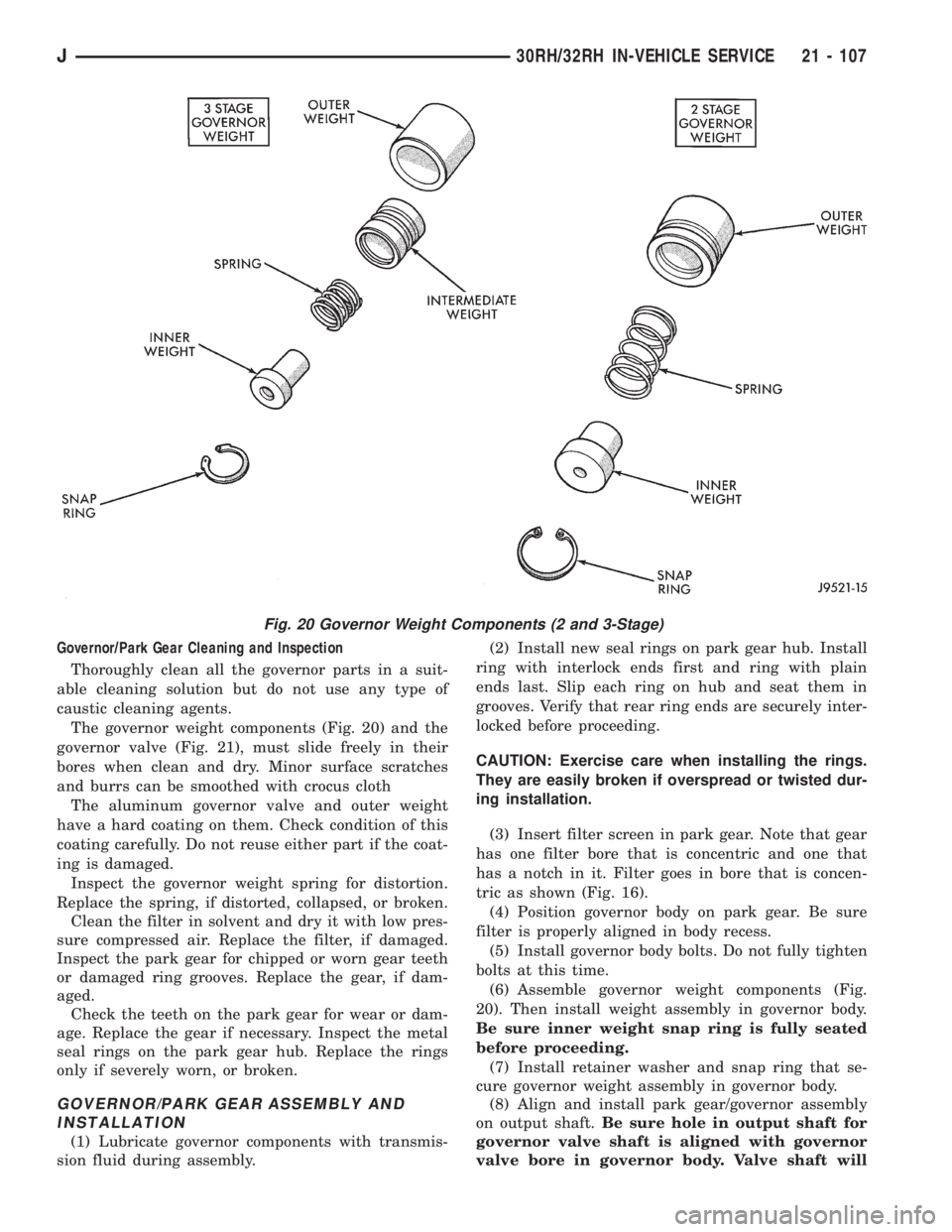
The governor weight components (Fig. 20) and the
governor valve (Fig. 21), must slide freely in their
bores when clean and dry. Minor surface scratches
and burrs can be smoothed with crocus cloth
The aluminum governor valve and outer weight
have a hard coating on them. Check condition of this
coating carefully. Do not reuse either part if the coat-
ing is damaged.
Inspect the governor weight spring for distortion.
Replace the spring, if distorted, collapsed, or broken.
Clean the filter in solvent and dry it with low pres-
sure compressed air. Replace the filter, if damaged.
Inspect the park gear for chipped or worn gear teeth
or damaged ring grooves. Replace the gear, if dam-
aged.
Check the teeth on the park gear for wear or dam-
age. Replace the gear if necessary. Inspect the metal
seal rings on the park gear hub. Replace the rings
only if severely worn, or broken.
GOVERNOR/PARK GEAR ASSEMBLY AND
INSTALLATION
(1) Lubricate governor components with transmis-
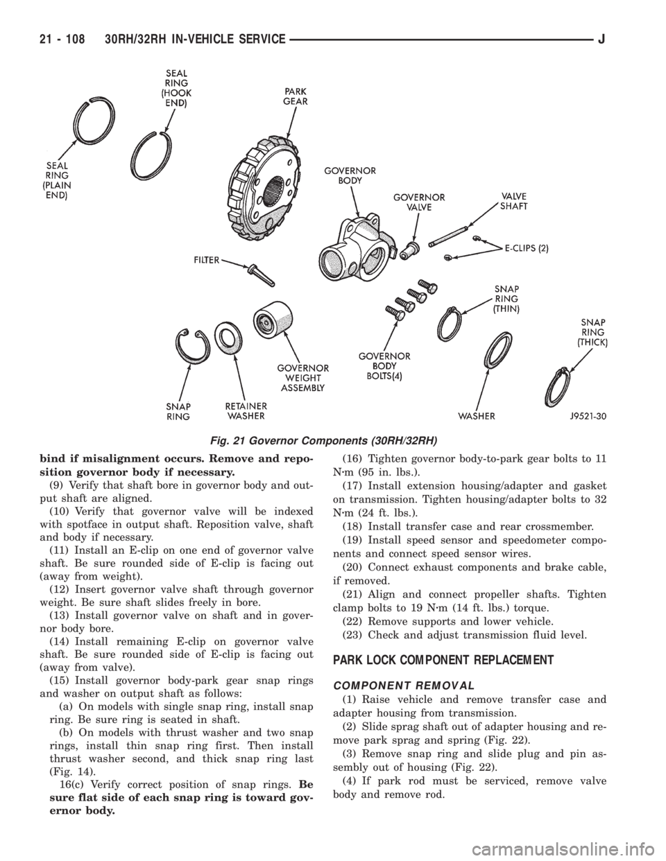
sion fluid during assembly.(2) Install new seal rings on park gear hub. Install
ring with interlock ends first and ring with plain
ends last. Slip each ring on hub and seat them in
grooves. Verify that rear ring ends are securely inter-
locked before proceeding.
CAUTION: Exercise care when installing the rings.
They are easily broken if overspread or twisted dur-
ing installation.
(3) Insert filter screen in park gear. Note that gear
has one filter bore that is concentric and one that
has a notch in it. Filter goes in bore that is concen-
tric as shown (Fig. 16).
(4) Position governor body on park gear. Be sure
filter is properly aligned in body recess.
(5) Install governor body bolts. Do not fully tighten
bolts at this time.
(6) Assemble governor weight components (Fig.
20). Then install weight assembly in governor body.
Be sure inner weight snap ring is fully seated
before proceeding.
(7) Install retainer washer and snap ring that se-
cure governor weight assembly in governor body.
(8) Align and install park gear/governor assembly
on output shaft.Be sure hole in output shaft for
governor valve shaft is aligned with governor
valve bore in governor body. Valve shaft will
Fig. 20 Governor Weight Components (2 and 3-Stage)
J30RH/32RH IN-VEHICLE SERVICE 21 - 107
Page 1670 of 2158
bind if misalignment occurs. Remove and repo-
sition governor body if necessary.
(9) Verify that shaft bore in governor body and out-
put shaft are aligned.
(10) Verify that governor valve will be indexed
with spotface in output shaft. Reposition valve, shaft
and body if necessary.
(11) Install an E-clip on one end of governor valve
shaft. Be sure rounded side of E-clip is facing out
(away from weight).
(12) Insert governor valve shaft through governor
weight. Be sure shaft slides freely in bore.
(13) Install governor valve on shaft and in gover-
nor body bore.
(14) Install remaining E-clip on governor valve
shaft. Be sure rounded side of E-clip is facing out
(away from valve).
(15) Install governor body-park gear snap rings
and washer on output shaft as follows:
(a) On models with single snap ring, install snap
ring. Be sure ring is seated in shaft.
(b) On models with thrust washer and two snap
rings, install thin snap ring first. Then install
thrust washer second, and thick snap ring last
(Fig. 14).
16(c) Verify correct position of snap rings.Be
sure flat side of each snap ring is toward gov-
ernor body.(16) Tighten governor body-to-park gear bolts to 11
Nzm (95 in. lbs.).
(17) Install extension housing/adapter and gasket
on transmission. Tighten housing/adapter bolts to 32
Nzm (24 ft. lbs.).
(18) Install transfer case and rear crossmember.
(19) Install speed sensor and speedometer compo-
nents and connect speed sensor wires.
(20) Connect exhaust components and brake cable,
if removed.
(21) Align and connect propeller shafts. Tighten
clamp bolts to 19 Nzm (14 ft. lbs.) torque.
(22) Remove supports and lower vehicle.
(23) Check and adjust transmission fluid level.
PARK LOCK COMPONENT REPLACEMENT
COMPONENT REMOVAL
(1) Raise vehicle and remove transfer case and
adapter housing from transmission.
(2) Slide sprag shaft out of adapter housing and re-
move park sprag and spring (Fig. 22).
(3) Remove snap ring and slide plug and pin as-
sembly out of housing (Fig. 22).
(4) If park rod must be serviced, remove valve
body and remove rod.
Fig. 21 Governor Components (30RH/32RH)
21 - 108 30RH/32RH IN-VEHICLE SERVICEJ
Page 1696 of 2158
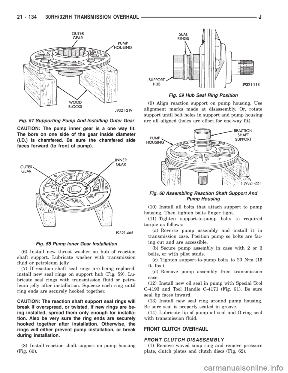
CAUTION: The pump inner gear is a one way fit.
The bore on one side of the gear inside diameter
(I.D.) is chamfered. Be sure the chamfered side
faces forward (to front of pump).
(6) Install new thrust washer on hub of reaction
shaft support. Lubricate washer with transmission
fluid or petroleum jelly.
(7) If reaction shaft seal rings are being replaced,
install new seal rings on support hub (Fig. 59). Lu-
bricate seal rings with transmission fluid or petro-
leum jelly after installation. Squeeze each ring until
ring ends are securely hooked together.
CAUTION: The reaction shaft support seal rings will
break if overspread, or twisted. If new rings are be-
ing installed, spread them only enough for installa-
tion. Also be very sure the ring ends are securely
hooked together after installation. Otherwise, the
rings will either prevent pump installation, or break
during installation.
(8) Install reaction shaft support on pump housing
(Fig. 60).(9) Align reaction support on pump housing. Use
alignment marks made at disassembly. Or, rotate
support until bolt holes in support and pump housing
are all aligned (holes are offset for one-way fit).
(10) Install all bolts that attach support to pump
housing. Then tighten bolts finger tight.
(11) Tighten support-to-pump bolts to required
torque as follows:
(a) Reverse pump assembly and install it in
transmission case. Position pump so bolts are fac-
ing out and are accessible.
(b) Secure pump assembly in case with 2 or 3
bolts, or with pilot studs.
(c) Tighten support-to-pump bolts to 20 Nzm (15
ft. lbs.).
(d) Remove pump assembly from transmission
case.
(12) Install new oil seal in pump with Special Tool
C-4193 and Tool Handle C-4171 (Fig. 61). Be sure
seal lip faces inward.
(13) Install new seal ring around pump housing.
Be sure seal is properly seated in groove.
(14) Lubricate lip of pump oil seal and O-ring seal
with transmission fluid.
FRONT CLUTCH OVERHAUL
FRONT CLUTCH DISASSEMBLY
(1) Remove waved snap ring and remove pressure
plate, clutch plates and clutch discs (Fig. 62).
Fig. 57 Supporting Pump And Installing Outer Gear
Fig. 58 Pump Inner Gear Installation
Fig. 59 Hub Seal Ring Position
Fig. 60 Assembling Reaction Shaft Support And
Pump Housing
21 - 134 30RH/32RH TRANSMISSION OVERHAULJ
Page 1700 of 2158
REAR CLUTCH OVERHAUL
REAR CLUTCH DISASSEMBLY
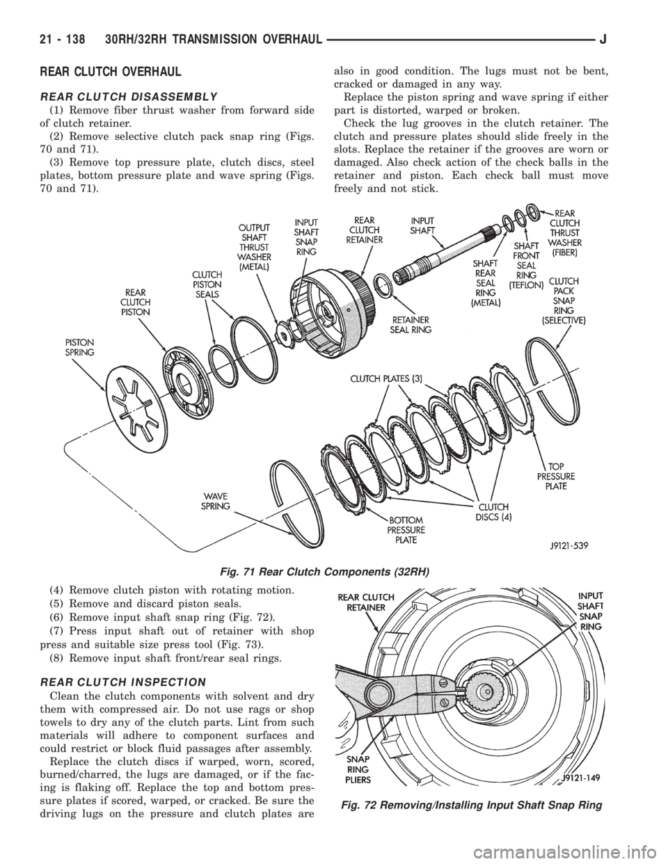
(1) Remove fiber thrust washer from forward side
of clutch retainer.
(2) Remove selective clutch pack snap ring (Figs.
70 and 71).
(3) Remove top pressure plate, clutch discs, steel
plates, bottom pressure plate and wave spring (Figs.
70 and 71).
(4) Remove clutch piston with rotating motion.
(5) Remove and discard piston seals.
(6) Remove input shaft snap ring (Fig. 72).
(7) Press input shaft out of retainer with shop
press and suitable size press tool (Fig. 73).
(8) Remove input shaft front/rear seal rings.
REAR CLUTCH INSPECTION
Clean the clutch components with solvent and dry
them with compressed air. Do not use rags or shop
towels to dry any of the clutch parts. Lint from such
materials will adhere to component surfaces and
could restrict or block fluid passages after assembly.
Replace the clutch discs if warped, worn, scored,
burned/charred, the lugs are damaged, or if the fac-
ing is flaking off. Replace the top and bottom pres-
sure plates if scored, warped, or cracked. Be sure the
driving lugs on the pressure and clutch plates arealso in good condition. The lugs must not be bent,
cracked or damaged in any way.
Replace the piston spring and wave spring if either
part is distorted, warped or broken.
Check the lug grooves in the clutch retainer. The
clutch and pressure plates should slide freely in the
slots. Replace the retainer if the grooves are worn or
damaged. Also check action of the check balls in the
retainer and piston. Each check ball must move
freely and not stick.
Fig. 71 Rear Clutch Components (32RH)
Fig. 72 Removing/Installing Input Shaft Snap Ring
21 - 138 30RH/32RH TRANSMISSION OVERHAULJ